Fatigue failure & Fatigue mechanisms. Engineering Materials Chedtha Puncreobutr.
|
|
|
- Kathleen Gaines
- 5 years ago
- Views:
Transcription
1 Fatigue failure & Fatigue mechanisms Engineering Materials Department of Metallurgical Engineering Chulalongkorn University
2 Fracture Mechanism Ductile fracture Occurs with plastic deformation Brittle fracture Occurs with Little or no plastic deformation Thus they are Catastrophic meaning they occur without warning! 2

3 Ductile VS Brittle Fracture behavior: Very Ductile Moderately Ductile Brittle Ductile fracture is nearly always desirable! %Ra or %El Large Moderate Ductile: warning before fracture Small Brittle: No warning 3

4 Moderately Ductile Failure Evolution to failure: necking s void nucleation void growth and linkage shearing at surface fracture Fracture surface of tire cord wire loaded in tension. Courtesy of F. Roehrig, CC Technologies, Dublin, OH. 4

5 Ductile VS Brittle cup-and-cone fracture brittle fracture 5

6 Brittle fracture Arrows indicate point at which failure originated 6
7 Fast fracture The condition for the onset of fast fracture, which is general for all engineering structures σ πa = EG c The critical combination of stress and crack length at which fast fracture commences is a material constant Stress intensity factor K = Yσ πa Crack would propagate by fast fracture when K = K c 7
 under repeated alternating or cyclic stresses of an")

, Callister 7e. (Fig. 22.30(b) is courtesy of National Semiconductor Corporation.")
8 Fatigue failure Fatigue failure is defined as the tendency of a material to fracture by means of progressive brittle cracking (slow crack growth) under repeated alternating or cyclic stresses of an intensity considerably below the normal strength. Ship-cyclic loading from waves. Adapted from chapter-opening photograph, Chapter 8, Callister 7e. (by Neil Boenzi, The New York Times.) Computer chip-cyclic thermal loading. Adapted from Fig (b), Callister 7e. (Fig (b) is courtesy of National Semiconductor Corporation.) Hip implant-cyclic loading from walking. Adapted from Fig (b), Callister 7e. 8

9 The Crash of the Comet Aircraft 9
10 Fatigue failure Fatigue failure = Failure under fluctuating stress Process of slow crack growth under fluctuating / cyclic stresses, failure can occur at lower loads than under a static load. 90% of all failures of metallic structures (bridges, aircraft, machine components, etc.) Fatigue failure is brittle-like even in normally ductile materials. Thus sudden and catastrophic! 10
11 Stress variation in wire cross section tension compression compression tension 12

12 Fluctuating stress with time stress induced at a point with respect to time or s a 13
13 Fluctuating stress with time This fluctuating stress is root cause of fatigue failure. It will initiate micro crack. Subsequently this crack will begin to grow with fluctuating load and over time it will cause an abrupt failure. Unlike failure due to static load failure due to fatigue happens without any warning, it does not make necking. And the failure is unpredictable. 17

14 Cyclic stress -> Fatigue crack Fatigue crack propagation in Aluminium 18


15 Fatigue Testing Fatigue tests are done by subjecting specimens of the material to a cyclically varying load or displacement fatigue can cause part failure, even though s max < s c. The specimens are subjected to increasing numbers of fatigue cycles N, until they finally crack (when N = N f the number of cycles to failure) 19
16 Cyclic Stresses s N Mean stress s m = (s max + s min ) / 2 Range of stress s = (s max - s min ) Stress amplitude s a = s/2 = (s max - s min ) / 2 Stress ratio R = s min / s max 20


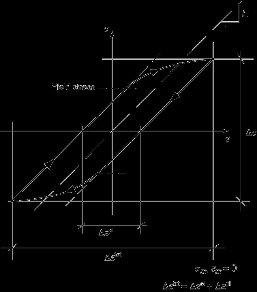
17 Stress-Strain relationship Coupling of cyclic stress and cyclic strain for a linear elastic specimen. Coupling of cyclic stress and cyclic strain for a linear elastic/yielding specimen. 21

18 Total strain amplitude VS fatigue life Low cycle fatigue - high loads - less than about 10 4 cycles - plastic stain > elastic strain High cycle fatigue - low loads - more than about 10 4 cycles - elastic stain > plastic strain 22

19 Total stress amplitude VS fatigue life 23
![Stress Amplitude & Number of Cycles [S-N Curve] s ut log s s ut This limit is known as endurance limit or fatigue limit Below endurance limit](/docs-images/90/102395094/images/20-1.jpg "it is safe to operate the material. Engineers always try to design their components by keeping stress amplitude below endurance limit. s e 24")
20 Stress Amplitude & Number of Cycles [S-N Curve] s ut log s s ut This limit is known as endurance limit or fatigue limit Below endurance limit it is safe to operate the material. Engineers always try to design their components by keeping stress amplitude below endurance limit. s e 24
21 S-N Curve Fatigue strength: Stress at which fracture occurs after specified number of cycles (e.g ) Fatigue life: Number of cycles to fail at specified stress level 25
22 S-N Curve 26
23 When mean stress is not zero Fluctuating stress case which is not fully reversed (i.e. s m > 0) 29
24 Goodman Diagram When mean value of zero, we know safe stress limit is same as endurance limit. When amplitude of stress is zero, it is same as a static loading condition. Safe stress amplitude limits for other cases lie on straight lines connecting this points 30

25 Fracture of cracked components Large structures particularly welded structures such as bridges, ships, oil rigs, and nuclear pressure vessels always contain cracks. cyclic stress intensity K K = K max K min = Y σ πa 31
 because the crack grows in tension")
26 Fracture of cracked components Cyclic stress intensity increases with time (at constant load) because the crack grows in tension 32

27 Fatigue Mechanism Cracks in material grows incrementally da dn A K m ~ s a typ. 1 to 6 increase in crack length per loading cycle crack grew even though K max < K c 33
28 Fatigue Mechanism Note that, at a given stress level, the crack growth rate, da/dn, increases with increasing crack length, and, for a given crack length such as a 1, the rate of crack growth is significantly increased with increasing magnitude of stress. 34
.")
29 Crack growth in LCF General plasticity quickly roughens the surface, and a crack forms there, propagating first along a slip path (Stage1). Then, it can grow normal to the tensile axis (Stage2) 35

30 Crack growth in HCF Local plasticity wherever a notch or scratch or change of section concentrates A crack ultimately initiates in the zone of one of these stress concentrations and propagates, slowly at first, and then faster, until the component fails. 36
31 Fatigue Mechanism Three stages: 1. crack initiation in the areas of stress concentration (near stress raisers i.e. microcracks, scratches, indents, interior corners, dislocation slip steps, etc.) 2. incremental crack propagation 3. rapid crack propagation after crack reaches critical size 37

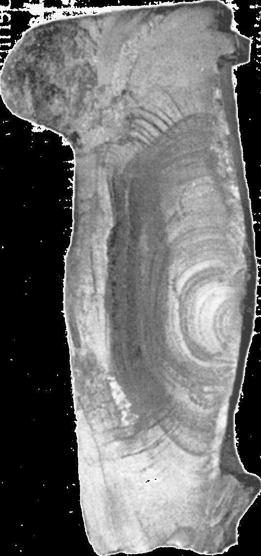
32 Fatigue crack surface in a steel plate The arrows show the direction of crack growth. 38

33 Fatigue crack in the deck of a ship. 39
34 Improving Fatigue Life 1. Impose a compressive surface stresses (to suppress surface crack growth) S = stress amplitude Increasing s m near zero or compressive moderate tensile s m Larger tensile s m s m N = Cycles to failure 40
35 Improving Fatigue Life 1. Impose a compressive surface stresses (to suppress surface crack growth) shot peening shot put surface into compression 41

36 Improving Fatigue Life 2. Remove stress concentrators. bad better bad better 42

37 Improving Fatigue Life 3. Improving the fatigue strength of a typical welded connection. 43


38 Designing out fatigue stresses 44

39 The Comet Air Disasters 45

40 The Comet Air Disasters 46


41 Eschede Railway Disaster 47


42 Eschede Railway Disaster 48