Synchrotron Imaging Techniques
|
|
|
- Carmel Marshall
- 5 years ago
- Views:
Transcription


1 Synchrotron Imaging Techniques Applications in materials science W. Ludwig 1,2, P. Cloetens 1, L. Helfen 1, P. Bleuet 1, M. Di Michiel 1 1 ESRF, Grenoble, France 2 Mateis, INSA de Lyon, France
2 Outline: Tomography endstations Sample environment Combination of techniques Fast tomography 100 µm Diffraction contrast tomography Topotomographic reconstruction of Al grain during recrystallization
3 Available setups / specifications ID19 : - high resolution µm pixelsize - coherence (145 m) - diffraction contrast tomography ID15 : ID17 : - high energy - fast tomography (few seconds) - simultaneous diffraction (strain measurement) - extra large field of view BM5 : - medium resolution (5-10 µm) ID22 : - fluorescence tomography - diffraction tomography ID22NI - projection microscopy - sub-micron resolution

4 Experimental setup Example: ID19 (ESRF) Long distance (145 m): coherence Multilayer monochromator:!"/"=10-2 High resolution detector system: 1 µm, 14 bit, CCD, 60 ms readout Dedicated µ-tomography set-up Sample environment: fatigue machine, cold cell, furnace,
5 Weak interaction with matter Refractive index n Aluminium Absorption vs. Phase Wavelength (Å) 10 n " n = 1 - # + i $ # >> $ # % electron density & phase $ = (" /4').µ & amplitude!/" 10 1 Soft X-rays Hard X-rays (water window) Energy (kev) Smallest detectable hole at 25 kev in an up to 4 mm thick sample: Absorption: 20!m Phase: 0.05!m


6 Holotomography of semisolid Al/Si alloy 4 distances: absorption m, 0.5 m and 0.9 m 800 angular positions multilayer monochromator: total time ( 40 minutes E = 18 kev Absorption Phase sensitive Holotomography 100 µm $-map edge enhancement Al/Si #-map Al


7 3D microstructure of Ti $21S alloy 30!m 50!m E.M. Lauridsen, R. Fonda, W. Ludwig et al.

 Tomorrow: Measurement of displacement fields in")
8 Comparison: visible vs. X-ray Ti-6Al-4V Today: Measurement of displacement fields in 2D (e.g. Roux, Hilde, et al. ) Tomorrow: Measurement of displacement fields in 3D Optical microscopy 2D µ-tomography 3D!
9 Sample environment Furnace(s) (ESRF) Cold cell (ESRF) Stress rig (INSA -Lyon) in-situ Fatigue machine (INSA-Lyon) hydraulic INSTRON stress rig (ESRF, ex-situ) your initiative!

 of Al bicrystal after 1h in contact with Sn melt at 620 C")
10 Furnace with 360 visibility (quartz cell) Up to 1000 C under vacuum + vacuum or controlled atmosphere camera can be set at 20 mm from the sample Sample 100µm X-ray microradiograph (ID19, 18 kev) of Al bicrystal after 1h in contact with Sn melt at 620 C 15 cm

11 Gas-blower furnace (ESRF)


12 Sample environment! Refrigerated cell 120 K-320 K Cold! CEN, METEO FRANCE Laboratoire de Glaciologie et Géophysique de l'environnement 100 µm 1 mm


13 GEMPPM UMR CNRS 5510! Tension/compression stage (displacemement controled) +/- 2500N translation speed: from 0.1 µm/s to few mm/s max displacement between 5 mm and 1 cm Sample PMMA tube

14 Fatigue machine (INSA-Lyon) - Mounts directly on sample stage - Polymer tube - Maximum load 1000 N - Tension / Tension - up to 50 Hz


 3D")
15 Example: characterization of fatigue crack 50!m short fatigue crack (phase contrast) crack and grain boundaries (Ga decoration) 3D rendering after morphological segmentation
16 Special tomographic imaging techniques Fluorescence tomography (ID22) - map 3D element distribution Laminography (ID19) - tomography on flat samples Projection Microscopy (ID22 NI) - down to 200 nm, holotomography Topo-Tomogaphy (ID19) - map 3D defect distribution inside one grain Diffraction contrast tomography (ID19) - map 3D grain structure of undeformed polycrystals
17 X-ray Fluorescence Tomography + 3D distribution / concentration map of chemical elements - slow (scanning technique) - Restrictions on size / type of materials Detector KB Box Diode #1 Sample Beam Diode #2


18 Environmental science example Rb Fe Mn Rb Fe Mn Absorption Fluorescence X Golosio et al., App. Phys. Lett Single waste Fly ash particle
19 X-ray Laminography Imaging flat samples: -> microelectronics ID19 insertion device 140 m rotation axis )! CCD sample multilayer monochromator goniometer system L. Helfen et al.


20 Imaging of Flip-chip interconnects 200 µm Flip-chip interconnections: 180 µm Pitch 200 µm Helfen et al.
21 X-ray microscopy techniques Projection Microscopy: Structure Dose efficient, fast Phase contrast Scanning Microscopy Fluorescence, Spectroscopy Slow Rich, trace elements Phase contrast Full-field microscopy Structure Dose inefficient, fast Absorption + phase

22 Measurement of grain displacements at the 10 nm level 50µm xrd 13 3 xrd xrd Ga thickness Ga thickness (nm) 0 X-ray beam direction t = 0 s: arrival of liquid Ga at the level of the ROIs E. Pereiro-Lopez, W. Ludwig et al. PRL (2005)


23 Magnified Tomography CuAl 2 particles in Al matrix Inside ) = 1 mm sample E = 20.5 kev X-ray magnification = um R. Mokso, et al. submitted
 10 µm Advantages:")

24 Mapping Polycrystals in 3D Conventional techniques: - Serial sectionning + EBSD - Focused Ion Beam (FIB) 10 µm Advantages: Problems: + works on deformed material + fully automated imaging mode + high in-plane resolution - characterization time - destructive
 Two basic reconstruction strategies: 1) solve the inverse problem (ART) 2 )")
25 3D X-ray Diffraction Microscopy Poulsen, Lauridsen, Schmidt et al. (Risoe) Two basic reconstruction strategies: 1) solve the inverse problem (ART) 2 ) solve the forward problem

26 Combination of 3D imaging and 3D diffraction? X-ray tracking Non- destructive diffraction technique Crystallographic orientation & 3D grain contour beam sample 2 dimensional detector 2" 2 y! x z 2" 1 beam stop # 1 # 2 0 L 1 L 2 L 3 Principle of the X-ray tracking technique (H.F. Poulsen et al., Risoe)
27 Diffraction contrast tomography Goal Characterize shape and orientatation of all grains simultaneously with the absorption microstructure Principle: (1) Run optimised tomography scan in conventional alignment (2) Extract grain projections (3) Sort diffraction spots with respect to grains of origin (4) Grain by grain tomographic reconstruction (2D-ART)
28 New tomographic approaches Ludwig, Poulsen, Schmidt, Lauridsen et al. Basic idea: µ = µ absorption + µ diffraction I = I 0 e " # µt Two data acquisition strategies: 1) Topotomography 2 ) Diffraction contrast tomography


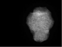
29 Diffraction contrast tomography Extraction of grain projections - = Measured projection Calculated absorption Grain projection


30 Sort diffraction spots with respect to grain of origin Vertical projection rotation axis

31 2D ART reconstruction 27 projections 5 iterations 100!m

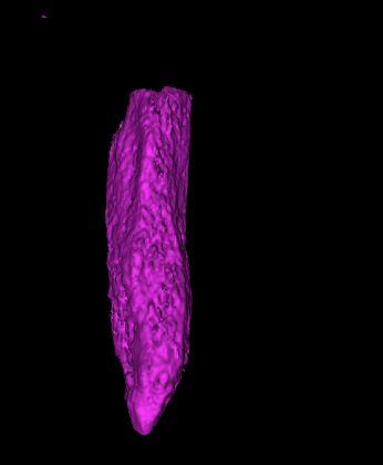
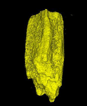
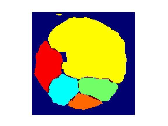
32 Grain by grain reconstruction 200!m

33 Known limitations... «missing grains»!: Can t handle orientation gradients spot overlap : < grains per cross-section
34 Mosaicity & Visibility I I *!*=0.1º!*=0.5º * STOP undeformed grain deformed grain Crystal monochromator and low mosaicity required!
35 Filtering of diffraction spots Filter: Vertical projection & sine movement
36 Combined acquisition
37 Conclusions Synchrotron Imaging: 3D microscope with 1µm resolution Dynamic 3D Imaging possible (few seconds minutes) Contrast mechanisms: absorption, phase, fluorescence, diffraction, etc X-ray Topography allows to image defects and distorsions under development Nanotomography : down to 50 nm resolution Characterization of 3D grain structure in polycrystals

38 Acknowledgements ESRF, Grenoble E. Pereiro-Lopez, P. Bleuet, P. Cloetens, P. Bernard, J. Baruchel, J. Haertwig, Risœ, Denmark H.F. Poulsen, E.M. Lauridsen, S. Schmidt, D.J. Jensen LGGE, Grenoble A. Philip, J. Meysonnier,

39 Topo-Tomography applied to Polycrystals 100!m

40 Topo-Tomography: data acquisition diffracted beam 100!m direct beam


41 Topotomography Reconstruction from diffracted beam (180 projections) Reconstruction from direct beam (720 projections)
 Diffracted beam Direct")
42 FBP reconstruction (cone beam algorithm) Diffracted beam Direct beam
43 Topo-Tomography applied to recrystallisation ( first results) sample: deformed Al single crystal 46 Topotomo scans (45 angles, 20 sec) C annealing steps T [C] C scan scan scan
44 Topo-Tomography applied to recrystallisation 2D projection topographs 100!m
45 3D grain shape evolution during growth 3D reconstruction (diffracted beam) ART reconstruction 45 projections 100!m

46 Tomographic reconstruction of final grain shape diffracted beam 200!m direct beam
 FBP, 360 projections")
47 Tomographic reconstruction of final grain shape 3D reconstruction (diffracted beam) FBP, 360 projections 100!m