Novel Technologies for Similar and Dissimilar Titanium Joints
|
|
|
- Oswin Parker
- 5 years ago
- Views:
Transcription
1 Novel Technologies for Similar and Dissimilar Titanium Joints October 8, 2012 Michael Eff Project Engineer

2 EWI. dedicated to Materials Joining and related process development activities Not-for-Profit Project Based Development Continuous development activities Single & group development programs Facility 132,000 ft 2 manufacturing development Staff 150 dedicated, experienced staff Most EWI engineers hold advanced degrees Many are well known for their skills in the industry Most EWI engineers have significant industrial experience Engineering Disciplines Welding, Material Science, Mechanical, Electrical, Design, Manufacturing, Industrial Systems, Ceramics, and Chemistry Global presence and networking capability.

 Typically used for joining material in a butt- or lap-joint configuration Solid-state process Joint thickness from")
3 Novel Joining Technologies Electro-Spark Deposition (ESD) Typically used for surface crack repair and coating Recently applied as a joining method Typical joint thickness <0.125-in Can be applied to a variety of material combinations Refractory alloys, Ti, steel, Al, Cu, and others Friction Stir Welding (FSW) Typically used for joining material in a butt- or lap-joint configuration Solid-state process Joint thickness from to 1.0-in. Used to join Al, Cu, Mg, steel, Ti, Ni, and some dissimilar combinations
 to -50 substrate Current (A)")
4 Electro-Spark Deposition (ESD) Process Fundamentals ESD processing characteristics Repetitive fire of a capacitive discharge power supply Discharge pulse widths are approximately 35 μsec Peak currents are ~100s of amps ESD torch Hand held or fixed position 250 Rotating electrode Short circuit sparking 100 Transfer of small metal 50 0 volumes (microns) to -50 substrate Current (A) Time (micro-seconds)

 Non equilibrium solidification and suppression of solid-state")
5 Electro-Spark Deposition (ESD) Process Fundamentals ESD deposit characteristics Deposit layers typically microns thick Deposition rates typically <100 μg/sec Multiple layers used to create a deposit Virtually no heating of the substrate Application to complex materials joining problems Achieves a fine material grain structure Fast cooling rates (> o C/s) Non equilibrium solidification and suppression of solid-state transformations
 Arc and Laser Processes: ESD: VRx Q 2 T e To 2 KR 1 x Cp Tm To T Tm Tm To erf xsp H m dt Arc and Laser Processes: dt ESD: 2 C p dt dt x H 2 sp V K T T Q 2")
6 Thermal Analysis of Various Localized Deposition Processes Temp (deg C) GTAW PAW PTA LBW ESD Distance (mm) Arc and Laser Processes: ESD: VRx Q 2 T e To 2 KR 1 x Cp Tm To T Tm Tm To erf xsp H m dt Arc and Laser Processes: dt ESD: 2 C p dt dt x H 2 sp V K T T Q 2 2 o m T T 2 m o


7 ESD Welding Mo-47%Re to Hastelloy X Procedure included Welded ESD Joint Fill of initial groove Formation of back groove Filling back groove Side plates used as run-on/-run-off Fill is nominally >99% dense Splat size nominally 10-μm thick Fill showed good adhesion to both components Processing time: 8 hr/specimen Cross-section
 per sample Analysis Metallographic cross-sections Microscopy Optical, SEM, and EDS ESD Parameters Used Pulse Rate 400 Hz Capacitance 70 f Voltage 150 V")
8 ESD Welding Dissimilar Metal Joining Materials Ti-6Al-4V to 1010 Steel & Ti-6Al-4V to IN718 Welding performed in argon-filled glove box Samples ground to 320 finish before welding Samples weighed before and after welding 10 passes (layers) per sample Analysis Metallographic cross-sections Microscopy Optical, SEM, and EDS ESD Parameters Used Pulse Rate 400 Hz Capacitance 70 f Voltage 150 V Electrode RPM 1200 Primary Amperage 6A

9 ESD Welding Ti-6Al-4V onto 1010 Steel Deposit characteristics Extreme cracking and breaking of deposit Inconsistent deposit thickness No distinguishable HAZ Multiple constituents present Turbulent mixing of constituents 3-4 constituents seen in deposit Large amount of Fe throughout deposit Ti-6Al-4V was not detected by EDS Suggesting large amounts of dissolution Compositional measurements of the constituents Compositions do not show typical solidification patterns Compositions do not correlate to Intermetallics Eutectics Overlay of ESD Results


10 ESD Welding Ti-6Al-4V onto IN718 Deposit characteristics Some areas free of cracking and porosity No distinguishable HAZ Multiple constituents present Less mixing of constituents Mixing mostly seen near the interface Ti-6Al-4V identified in deposit layer Suggesting less dissolution than between the Ti-6Al-4V to steel Likely caused by low thermal conductivity Dissolution still seen near interface Compositional measurements made of the constituents Compositions do not show typical solidification patterns Compositions do not correlate to Intermetallics Eutectics Overlay of ESD Results
 Electrode Melting Temp. (C) Subst.")


11 ESD Welding Differences in Deposition Behavior Material Combination Electrode/Substrate Subst. Melting Temp. (C) Electrode Melting Temp. (C) Subst. Thermal Diffusivity (W/m-K) Pulse Width Pulse Height (A) Ti 6Al4V/1010 Steel Hastelloy-X/T Hastelloy-X/MarM Ti-Steel Hastelloy-X T-111 Hastelloy-X MarM-247 Note the very fine interface from a short pulse width. This suggests pulse width plays a larger role than material properties.
12 ESD Welding Current Waveform & Deposit Quality Increased pulse width Longer pulse widths increases the heat input and decreases the cooling rate Creating longer times at high temperatures Resulting in more substrate melting and mixing with the deposited layer Comparison with previous work suggests shorter pulse widths will decrease or eliminate cracking Successful deposits have been at less than 60-μs pulse width Current welding was done at pulse widths of μs Current (A) Previous Waveform Time (µs) Current Waveform


13 ESD Welding Metallurgical Implications for Dissimilar Material Joints Effects of high cooling rates on solidification Equally high solidification rates Dendritic solidification without segregation Solidification morphology surface tension rather than compositionally driven Elimination of drivers for solidification cracking Potential for a wide range of solid-solution phases Effects on solid-state phase transformations High cooling rates suppress second phases Allows super-saturated phases to exist at room temperature Potential for complex phase distributions with postweld heating Parallels in other pulse weld technologies Magnetic pulse welding Percussion welding Pulse width is a crucial variable in ESD Large effect on heat input and cooling rate Pulse widths of 90 to 100 μs result in voids and cracking Pulse widths less than 60 μs are more successful for joining dissimilar materials Hastelloy X Deposit on a Mo- 47%Re Substrate Hastelloy X Deposit on a Ta-111 Substrate with a Narrow Pulse Width Al Deposit on Cu with a Wide Pulse Width
14 Friction Stir Welding (FSW) Solid-state joining process Originally developed for joining aluminum Uses a 3 rd body tool rotating as the heat source Tool rotates and traverses along a joint Work has extended the process to welding of hard metals Steel, Titanium, Nickel


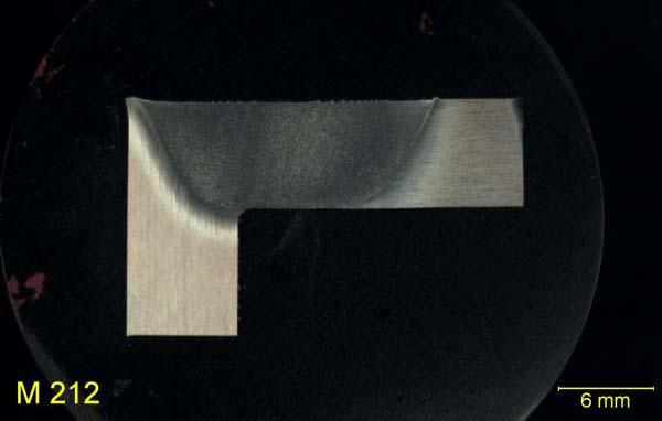
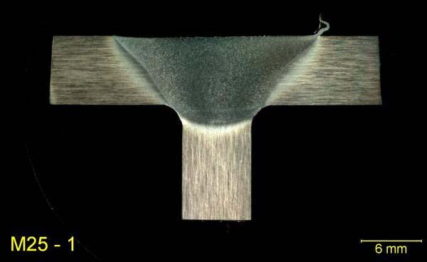
15 FSW Ti-6Al-4V Structural Geometries Butt, Corner and T-Joint example geometries >1-in. Penetration 60-in. T- Joint 48-in. Butt Joint 24-in. Corner Joint

16 FSW Ti-6Al-4V Welded Structures


17 FSW Ti-6Al-4V Additive Manufacturing Additive manufacturing is now being widely considered Opportunity for material savings Rapid prototyping method 3-Layer Ti-6Al-4V Build-up Spiral Raster Pattern
18 FSW Ti-6Al-4V Static Mechanical Properties (ksi) GMAW-P Aswelded Transverse GMAW-P Aswelded Longitudinal UTS Yield Strength Elongation GMAW-P PWHT Transverse GMAW-P PWHT Longitudinal FSW Asw elded Transverse FSW Asw elded Longitudinal FSW PWHT Transverse FSW PWHT Longitudinal (%) Post-weld heat treatment: 1150ºF, 2 hrs. Tested per ASTM E8 Sub-size specimens (1.0-in. gauge length and 0.25-in. diameter) Room temperature Weld metal failure in the GMAW-P (pulsed) specimens HAZ failures in the FSW specimens
19 Questions
20