MILITARY STANDARD RADIOGRAPHIC REFERENCE STANDARDS AND RADIOGRAPHIC PROCEDURES FOR PARTIAL-PENETRATION ALUMINUM WELDS
|
|
|
- Bertha Rich
- 5 years ago
- Views:
Transcription

1 20 October 1986 SUPERSEDING MIL-STD-1895(AT) 27 June 1984 MILITARY STANDARD RADIOGRAPHIC REFERENCE STANDARDS AND RADIOGRAPHIC PROCEDURES FOR PARTIAL-PENETRATION ALUMINUM WELDS AMSC N/A DISTRIBUTION STATEMENT A. AREA NDTI Approved for public release; distribution is unlimited.
2 DEPARTMENT OF DEFENSE Washington, DC Radiographic Reference Standards and Radiographic Procedures for Partial-Penetration Aluminum Welds 1. This Military Standard is approved for use by all Departments and Agencies of the Department of Defense. 2. Beneficial comments (recommendations, additions, deletions) and any pertinent data which may be of use in improving this document should be addressed to : US Army Tank-Automotive Command, ATTN: AMSTA-GDS, Warren, MI , by using the self-addressed Standardization Document Improvement Proposal (DD Form 1426) appearing at the end of this document, or by letter. ii
3 FOREWORD This document contains selected radiographs illustrating various types and degrees of discontinuities occurring in partial-penetration aluminum welds. It also contains instructional data concerning radiographic inspection of this type of weldment. It is intended that this document provide the following: a. A weld discontinuity severity range for designers to select standards for acceptance inspection. b. Reference standards for acceptance personnel to evaluate the quality of production weldments. c. Guide lines for radiographers to effectively accomplish radiographic examination of partial penetration welds. The reference standards included in this document were prepared by the U.S. Army Tank-Automotive Command under project authorization of the U.S. Army Materials Technology Laboratory. iii
4 CONTENTS Paragraph *1.3 4, SCOPE Scope Classification REFERENCED DOCUMENTS Government documents Specifications, standards and handbooks Other publications Order of precedence DEFINITIONS Partial penetration joint design Radiation angle Radiograph Radiographic inspection Discontinuity Unfused area Flaw Penetrameter/Image quality indicator Metallographic cross sections Welding terms and definitions Gas metal arc welding (GMAW) Gas tungsten arc welding (GTAW) GENERAL REQUIREMENTS Radiographic location Radiographic frequency Radiation angle Penetrameter requirements Acceptance standards Discontinuity types Discontinuity grading DETAILED REQUIREMENTS Application of reference standards Determination of acceptability Quality level of radiographic sensitivity Rules 1 and Single discontinuity Multiple discontinuities False indications Inspection records NOTES Intended use Subject term (key word) listing Page(s) iv
5 CONTENTS - Continued. Page(s) Figure(s) FIGURES Recommended radiation angle and film location for typical partial-penetration joints Correct and incorrect radiographic procedure for joint design (c) Reference standards for fine scattered porosity in aluminum welds Reference standards for coarse scattered porosity in aluminum welds Reference standards for linear porosity in aluminum welds Reference standards for clustered porosity in aluminum welds Reference standards for gas cavities in aluminum welds Examples of incomplete penetration correlated with weld cross-sections in aluminum welds Examples of lack of fusion correlated with weld cross sections in aluminum welds v
6
7 1. SCOPE 1.1 Scope. This standard provides standard reference radiographs and recommended radiographic inspection procedures for partial penetration weldments in aluminum plate, casting, or forging, 1/2 to 2 inches (12.70 to millimeter) thick. 1.2 Classification. The reference radiographs comprised in this standard are intended primarily for use on welds made with the gas in metal are welding and gas tungsten arc welding processes and may be manual or machine welded. 1
8 2. REFERENCED DOCUMENTS 2.1 Government documents Specifications, standards, and handbooks. Unless otherwise specified, the following specifications, standards, and handbooks of the issue listed in that issue of the Department of Defense Index of Specifications and Standards (DoDISS) specified in the solicitation form a part of this standard to the extent specified herein. STANDARDS MILITARY MIL-STD-410 MIL-STD-453 MIL-STD Nondestructive Testing Personnel Qualification and Certification. - Inspection, Radiographic. - Welding of Aluminum Armor. (Note: Negatives of radiographs illustrated in this standard can be purchased through AMSTA-GDS. Requests should be addressed to US Tank-Automotive Command, ATTN: AMSTA-GDS, Warren, MI ) (Copies of specifications, standards, handbooks, drawings, and publications required by manufacturers in connection with specific acquisition functions should be obtained from the contracting activity or as directed by the contracting officer.) 2.2 Other publications. The following documents form a part of this standard to the extent specified herein. The issues of the documents which are indicated as DoD adopted shall be the issue listed in the issue of the DoDISS specified in the solicitation. The issues of documents which have not been adopted shall be those in effect on the date of the cited DoDISS. AMERICAN SOCIETY FOR TESTING AND MATERIALS (ASTM) ASTM E142 ASTM E340 - Standard Method for Controlling Quality of Radiographic Testing. - Standard Method for Macroetching Metals and Alloys. (Application for copies should be addressed to American Society for Testing and Materials, 1916 Race Street, Philadelphia, PA, ) AMERICAN NATIONAL STANDARDS INSTITUTE (ANSI)/AMERICAN WELDING SOCIETY (AWS) ANSI/AWS A3.O - Standard Welding Terms and Definitions Including Terms for Brazing, Soldering, Thermal Spraying and Thermal Cutting. (Copies of the above publications may be obtained from the American Welding Society, Inc., 550 N. W. LeJeune Road, P.O. BOX 35104O, Miami, Florida ) 2
9 (Nongovernment standards are generally available for reference from libraries. They are also distributed among nongovernment standards bodies and using Federal agencies.) 2.3 Order of precedence. In the event of a conflict between the text of this standard and the references cited herein, the text of this standard shall take precedence. 3
10 3. DEFINITIONS 3.1 Partial penetration joint design. The term partial-penetration joint as used in this standard is defined as a weld joint containing an intentionally unfused area in the central portion of the joint. Examples of typical partial-penetration joint designs are shown in figures 1, 2, and Radiation angle. This term refers to the angle from any given plane to the central beam of radiation as shown in figure Radiograph. A visible image on an X-ray sensitive recording medium produced by the penetration of radiation through the materials being tested as defined in MIL-STD Radiographic inspection. The use of X-rays or gamma rays to detect discontinuties in material by presenting their images on a recording medium suitable for interpretation by qualified personnel Discontinuity. As defined in ANSI/AWS A3.0, a discontinuity is an interruption of the typical structure of a weldment, such as a lack of homogeneity in the mechanical, metallurgical or physical characteristics of the material or weldment. A discontinuity is not necessarily a defect Unfused area. In partial penetration weldments the intentionally unfused area does not constitute a discontinuity, flaw or defect (see 3.1) Flaw. As defined in ANSI/AWS A3.0, a flaw is a near synonym for discontinuity, but with an undesirable connotation. 3.4 Penetrameter/Image Quality Indicator. A strip of metal the same composition as that of the metal being tested, representing a percentage of object thickness and provided with a combination of steps, holes, and/or slots. Its image on a radiograph is used to determine the radiographic quality level. It is not intended for use in judging the size nor for establishing acceptance limits of discontinuities. Examples of penetrameters are shown in figures 5, 7, 9, 11 and Metallographic cross sections. Cross sections through the welds as shown in figures 4 through 15 which are cut perpendicular to the direction of welding, polished and etched as specified in ASTM E-340. These samples show internal discontinuity, depth of weld penetration, weld size, and other characteristics of the weldment. 3.6 Welding terms and definitions. Welding symbols, terms and definitions shall be as specified in ANSI/AWS A3.O Gas metal arc weldin g (GMAW). An arc welding process that produces coalescence of metals by heating them with an arc between a continous filler metal electrode and the workplaces. Shielding is obtained entirely from an externally supplied gas. 4
11 3.6.2 Gas tungsten arc weldin g (GTAW). An arc welding process that produces coalescence of metals by heating them with an arc between a tungsten electrode (nonconsumable) and the workplaces. Shielding is obtained from a gas. Pressure may or may not be used, and filler metal may or may not be used. 5
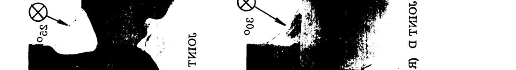
12 4. GENERAL REQUIREMENTS 4.1 Radiographic location. Weldments shall be radiographically inspected in the location specified on the applicable radiographic position chart drawing, component drawing, specification, or contract requirement. Radiographic inspection shall meet the requirements of MIL-STD-410 and MIL-STD Radiographic frequency. Establishment of radiographic frequency of spot checking of weldments shall be accomplished in accordance with MIL-STD-453 and MIL-STD A quality assurance plan approved by the procuring activity shall be used Radiation angle. Radiographic inspection of partial-penetration welds requires special consideration of joint design when selecting the radiation angle. The angle employed shall insure adequate coverage of the weld with minimum interference from the normally unfused area. Generally this can be achieved by directing the X-ray beam such that any possible incomplete penetration at both roots would be separated on the film by at least 1/8 inch (3.18 millimeter). Figure 4 illustrates the radiographic results of a correct and incorrect radiation angle. If a radiographic position chart is not available the recommended procedures shown on figures 1, 2, and 3 shall be used as a guide Penetrameter requirements. Each penetrameter shall be produced with three holes, one of which shall be of a diameter equal to twice the penetrameter thickness (2T). Penetrameters shall conform to the requirements of ASTM E142 and MIL-STD Acceptance standards. Designation of acceptance standards for each type of discontinuity illustrated in the reference standards shall be made by the procurement or design agency and shall be indicated on the applicable radiographic position chart, drawing, or contract requirement. 4.3 Discontinuity types. With the exception of cracks, the common discontinuities experienced in partial-penetration aluminum weldments are shown in the reference standards forming part of this document. These discontinuities are described below and shown in figures 5 through 13. All cracks shall be rejected; any deviation from this procedure will require approval from the Government procuring activity. a. Scattered porosity (fine and coarse). This discontinuity consists of scattered voids formed by gases failing to escape during weld metal solidification. On the radiograph these discontinuities are dark round or elongated spots of varying size and density. The average size of fine porosity is 1/32 inch (0.79 millimeter) in diameter and that of coarse porosity is 1/16 inch (1.59 millimeter) in diameter. b. Clustered porosity. Clustered porosity appears the same as scattered porosity except that the pores are concentrated in one area, generally at the start of a bead or an interrupted arc. 6
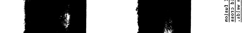
13 c. d. e. f. Linear porosity. The type most common in partial-penetration welds results from expanding gases generated in the normally unfused area. The cavities are linearly distributed at the root of the weld deposit and generally range from 1/32 inch (0.79 millimeter) in diameter to 1/16 inch (1.59 millimeter) in diameter. Gas cavities. This discontinuity generally results from inadequate shielding gas or severe contamination of the gas. It appears the same as scattered porosity except the average cavity size is approximately 1/8 inch (3.18 millimeter) in diameter. Incomplete (inadequate) penetration. In partial-penetration welds this discontinuity consists of a linear root void in excess of the unfused area normally present in this type of joint. It appears on the radiograph as a straight dark line at either root or at both roots. When present at both roots the two images should be separated if properly radiographer. Lack of fusion. Lack of fusion is failure of the weld metal to fuse completely with the base metal or with the preceding bead. Lack of fusion between the weld metal and base metal is most common in aluminum welds and is generally associated with incomplete penetration near the root of the weld. Examples of this are illustrated in figures 14 and 15. This discontinuity is very difficult to detect radiographically due to its hair-line condition and interference from the incomplete penetration void. 4.4 Discontinuity grading. Discontinuity severity grading of the refecence standards was selected to extend from standard 1, which represents a high-quality weld, to that of standard 5, which is indicative of poor workmanship and is usually rejected in commercial practice. 7
14 5. DETAILED REQUIREMENTS 5.1 Application of reference standards Determination of acceptability. Acceptability of production welds shall be determined by directly comparing the production radiograph with the designated reference standard for each type of discontinuity. In general the extent of discontinuity exhibited in the designated standard will be Permitted. throughout the length of any particular weld joint provided that the discontinuity content in any weld length equal to that of the reference standard does not exceed that shown in the standard. Exceptions to this are required for incomplete penetration and lack of fusion since acceptability of these discontinuities is based on material thickness. The examples shown in figures 14 and 15 are for illustration purposes only; the evaluation is described in Quality level of radiographic sensitivity. Figures 5, 7, 9, 11 and 12 illustrate the radiographic image quality level of 2-lT. MIL-STD-453 defines the formula as follows: Quality level inspection 1 Penetrameter designation 2-lT Maximum penetrameter thickness 2% expressed as a percentage of material thickness, T. Minimum penetrameter hole diameter expressed as a multiple of thickness of penetrameter. 1T Equivalent penetrameter 1.4% sensitivity express as a percentage of the specimen thickness in which a 2T hole would be clearly visible under the same radiographic conditions Rules 1 and 2. Incomplete penetration and lack of fusion shall be judged by image width and length. Unless otherwise specified by the Government procuring activity, the following rules shall apply: Rule 1. Rule 2. The average image width of any incomplete penetration line shall not exceed l/16 inch. The greatest accumulated length of all incomplete penetration lines in any weld length of 8T, where T equals the average plate thickness, shall not exceed the following: 8
15 MIL-STD 1895A IT for standard 1 2T for standard 2 4T for standard 3 6T for standard 4 8T for standard Single discontinuity. When the production radiograph shows but one type of discontinuity which is equal to or less severe than the designated acceptance standard specified for that type of discontinuity, the weld shall be considered radiographically acceptable. If the radiograph shows a discontinuity of greater severity than specified, then the weld shall be rejected, unless repair is permitted Multiple discontinuities. a. b. When the production radiograph shows two or more types of discontinuities to an extent equal to the designated acceptance standard for each type of discontinuity, then the weld shall be rejected, unless repair is permitted. When the production radiograph shows one predominant type of discontinuity to be equal to the designated acceptance standard and all other types to be less severe than the designated standard, then the weld shall be considered radiographically acceptable False indications. At times, radiographic films may indicate weld discontinuities when actually the film is defective. If doubt exists as to whether the discontinuity is in the weld or is a film imperfection, then the weld shall be radiographed again. 5.2 Inspection records. Radiographic reports and films shall be made available to the procuring activity in accordance with MIL-STD
16 6. NOTES 6.1 Intended use. This standard provides radiographic reference standards and procedures for partial penetration arc welding of aluminum. 6.2 Subject term (key word) listinq. Aluminum Welding Fusion Welding Inspection Partial Penetration Welds Radiation Angles Radiographic Reference Standards 10
17 MIL STD-1895A FIGURE 1. Recommended radiation angle and film location for ty pical partial- penetration joints. Page 11
18 MIL STD-1895A FIGURE 2. Recommended radiation angle and film location for typ ical partial-p enetration joints. Page 12
19 MIL STD-1895A FIGURE 3. Recommended radiation angle and film location for typical partial-penetration joints. Page 13
20 MIL-STD-l895A Figure 4: 14


 FIGURE 5:")


21 MIL-STD 1895A STD. 1 (APPROX. 6 PORES PER, SQ. IN) STD. 2 (APPROX. 12 PORES PER SQ. IN) FIGURE 5: Reference standards for fine scattered porosity in aluminum welds. 15

22 STD. 3 APPROX. 25 PORES/SQ. IN. STD. 4 APPROX. 50 PORES/SQ. IN. STD. 5 APPROX. 100 PORES/SQ. IN. FIGURE 6: Reference standards for fine scattered porosity in aluminum welds. 16

 REFERENCE STANDARDS FOR COARSE SCATTERED POROSITY - ALUMINUM WELDS FIGURE 7: Reference")
23 MIL STD-1895A 2-1T RADIOGRAPHIC SENSITIVITY CROSS SECTION OF COARSE SCATTERED POROSITY. ALL PLATES ARE JOINT A, RADIO- GRAPHED AS ILLUSTRATED. STD. 1 (APPROX. 2 PORES PER SQ. IN. STD. 2 (APPROX. 4 PORES PER. SQ. IN.) REFERENCE STANDARDS FOR COARSE SCATTERED POROSITY - ALUMINUM WELDS FIGURE 7: Reference standards for coarse scattered porosity in aluminum welds. 17
 STD. 4 (APPROX.")


24 STD. 3 (APPROX. 8 PORES PER. SQ. IN.) STD. 4 (APPROX. 16 PORES PER. SQ. IN.) STD. 5 (APPROX. 32 PORES PER. SQ. IN.) FIGURE 8: Reference standards, for coarse scattered porosity in aluminum welds. 18


25 MIL STD 1895A 2-1T RADIOGRAPHIC SENSITIVITY CROSS SECTION OF LINEAR POROSITY. ALL PLATES ARE JOINT A, RADIOGRAPH D AS ILLUSTRATED. STD. 1 STD. 2 FIGURE 9: Reference standards for linear porosity in aluminum welds. 19
26 STD. 3 STD. 4 STD. 5 FIGURE 10: Reference standards for linear porosity in aluminum welds. 20


27 MIL STD 1895A 2-1T RADIOGRAPHIC SENSITIVITY CROSS SECTION VIEW STD. 1 STD. 2 STD. 3 FIGURE 11: Reference standards for clustered porosity in aluminum welds. 21


28 MlL STD--l895A 2-1T RADIOGRAPHIC SENSITIVITY CROSS SECTION OF A LARGE GAS CAVITY. MOST PLATES ARE JOINT A, RADIO- GRAPHED AS ILLUSTRATED. STD. 1 STD. 2 FIGURE 12: Reference standards for gas cavities in aluminum welds. 22
29 MIL STD-l895A STD. 3 STD. 4 STD. 5 FIGURE 13: Reference standards for gas cavities in aluminum welds. 23
30 MIL-STD-l895A Figure 14: 24


31 Figure 15: 25
32 Custodian: Army - AT Air Force - 20 Preparing activity: Army - AT (Project NDTI-0123) Review Activities: Army - AR, AV *U.S. GOVERNMENT PRINTING 0FFICE: 1986/1224/
33
34