Development, Fabrication and Characterization of Fuels for Indian Fast Reactor Programme
|
|
|
- Avice Paul
- 5 years ago
- Views:
Transcription
1 Development, Fabrication and Characterization of Fuels for Indian Fast Reactor Programme Arun Kumar Radiometallurgy Division, Nuclear Fuels Group, Bhabha Atomic Research Centre, Trombay, Mumbai, India International Conference on Fast Reactors and Related Fuel Cycles: Safe Technologies and Sustainable Scenarios (FR13), Paris, March 4-7, 2013

2 Outline 1. Introduction 2. History of fast reactor fuels in India 3. Development and fabrication of mixed oxide and mixed carbide fuels 4. Development of metallic fuel and evaluation of its properties 5. CERMET fuel development 6. Conclusions
3 Introduction Road map of Indian nuclear power programme is to utilise judiciously scanty resource of Uranium and vast potential of Thorium. Use of Uranium in PHWRs and reprocessing of spent fuel to obtain Plutonium. Deployment of fast reactors using Plutonium bearing fuel for breeding of fissile material & increased power generation and U 233 generation by using Thorium/Thoria blanket Deployment of Th-U 233 fuelled reactors to achieve sustainability in power generation. Fast reactors can effectively utilise energy in Uranium and reduce the environmental burden of the spent fuel. Therefore, closed fuel cycle and deployment of fast reactors are essential for India not only for its contribution to nuclear power but for extension of its modest resources.
4 History of fast reactor fuel development in India Activity Year Fabrication of PuO 2 elements for PURNIMA Studies on natural UO 2-30% PuO 2 fuels Studies on high Pu (76%) MOX fuel for FBTR 1976 Developmental work on (U,Pu)C, (U,Pu)N and (U,Pu)CN Fabrication of (U 0.3 Pu 0.7 )C fuel (Mark -1) FBTR was made critical with (U,Pu)C cont. Fabrication of (U 0.45 Pu 0.55 )C fuel (Mark -II) Fabrication of MOX PFBR (UO 2-29%PuO 2 )test fuel assembly for test irradiation 1994 Development of high Pu MOX (44% Pu) fuel for FBTR Fabrication of (UO 2-21%PuO 2 ) and(uo 2-28%PuO 2 ) fuels for PFBR Studies on Pu based metallic fuel for FBRs 2007 FBTR fuel reaches a record burn-up of 165 GWd/t cont. Studies on thermophysical and compatibility studies on U-15%Pu binary alloy Development of CERMET fuel 2011-cont.


5 The Three Stages of the Indian Nuclear Programme U
6 Properties of Reference FBR Fuels Candidate fuels for fast reactors Oxides Metallic Carbides Properties (U 0.8 Pu 0.2 )O 2 (U 0.8 Pu 0.2 )C U-19Pu- 10Zr U-15 Pu (with Zr liner on clad) Heavy metal Density g/cc Melting point ºK Thermal conductivity (W/m ºK) 1000 K K Crystal structure Fluorite NaCl bcc ( ) Orthorhombic (α) Breeding ratio Doubling time ( y)
O 2 (U 0.8 Pu 0.")
7 Properties of Reference FBR Fuels Properties (U 0.8 Pu 0.2 )O 2 (U 0.8 Pu 0.2 )C U-19Pu-10Zr U-15 % Pu (with Zr liner on clad) Swelling Moderate High High High Handling Easy Inert atmosphere Inert atmosphere Inert atmosphere Compatibility - Clad Average Carburisation issue Eutectics formation issue Eutectics formation issue Coolant Average Good Good Good Dissolution & reprocessing amenability Established Demonstrated Pyroreprocessing Pyroreprocessing Fabrication/Irradi ation experience Large Good Good Indian Experience Limited No reported experience
8 Mixed Carbide
9 Initial Fuel Considered for FBTR No Fuel Remark 1. ( U 0.7 Pu 0.3 )O 2-x (U enriched to 85%) Not Implemented because of material non- availability 2. ( U 0.24 Pu 0.76 )O 2-y Not Implemented because of fuel / coolant non- compatibility, Lower thermal conductivity & fabrication difficulty Driver Fuel For FBTR MK I (U 0.3 Pu 0.7 )C MK II (U 0.45 Pu 0.55 )C March 12, 2013 FR 13, 5th March 2013


10 Mixed oxide fuel for FBTR Issues of high Pu bearing fuels U-Pu-O ternary phase diagram 1. Low thermal conductivity 2. Two phase structure 3. Not compatible with Na Hence MOX fuels containing >50% PuO 2 are not suitable UO 2 UO 2-30%PuO 2 UO 2-76%PuO 2 PuO 2
11 Mixed Carbide Fuel for FBTR, Kalpakkam (U 0.3 Pu 0.7 )C-Mk I was chosen as driver fuel for FBTR at Kalpakkam. Later FSAs containing (U 0.45 Pu 0.55 )C-Mk II was loaded in FBTR to expand the core. High thermal conductivity and metal density in MC lead to compact core & high breeding ratio. Performance of this fuel has been excellent and achieved record burn-up of 1,65,000 MWD/T. Technology is complex but can be adopted for small cores.
12 Mixed carbide fuels with high Pu enrichment has never been used as driver fuel for Fast Reactor Information relevant for design of high Pu carbide fuel were generated through indigenous experiments Thermo-physical properties (information available in the open literature was limited to 40wt% of PuC) Compatibility (fuel-clad) In-pile and out-of-pile properties of the fuel Fabrication of fuel
 ) is the test bed for development of")

13 Fast Reactor fuelled by a unique Pu rich mixed carbide Fast Breeder Test Reactor at Kalpakkam (40MW (th) ) is the test bed for development of fuel, blanket and structural materials for FBRs FBTR achieved criticality on October 18, 1985 with unique Pu rich mixed carbide fuel developed by BARC.
14 Thermal conductivity, W/m.K Property (Pu 0.7 U 0.3 )C MK I Melting point (K) Thermal expansion at K (x10-6 ) Thermal 500K Conductivity 1000K (W/m/K) 1400K Hot hardness at 1000K (GPa) (Pu 0.55 U 0.45 )C MK II Thermal conductivities of carbide and oxide MK-I MC MK-II UO 2-45%PuO Temperature, K MKII fuel has higher thermal conductivity than MK I up to 1100K. MK-II has lower coefficient of thermal expansion than MK-I ( K) MK-II has higher solidus temperature. This could lead to lower thermal creep. However, hardness vs. temperature plot indicates sharp change in slope at considerably lower temperature suggesting possibility of onset of thermal creep at lower temperature. Carbon potential of MK-II fuel is higher. More carburization of clad expected. However because of lower solubility of O in MK-II fuel the possibility of gas phase carburization of the clad gets reduced.
15 Fuel Specifications Specification Chemical Plutonium (wt%) Plutonium and Uranium (wt%) Oxygen (ppm) Oxygen + nitrogen (ppm) M 2 C 3 (wt%) Tungsten (ppm) Total impurities (ppm) (excluding oxygen, nitrogen, and americium) Physical Diameter (mm) Height (mm) (nominal) Density (% TD) Linear mass (g/cm) (Pu 0.7 U 0.3 )C MK I 66 ± to ± ± ± 0.04 (Pu 0.55 U 0.45 )C MK II 51.9 ± to ± ± ±
16 Mixed Carbide Fuel Fabrication Two major steps i. Preparation of mixed carbide clinkers by vacuum carbothermic reduction of mixed UO 2 & PuO 2 powder 0.3 UO PuO 2 + 3C = (U 0.3 Pu 0.7 )C + 2CO ii. Processing of mixed carbide clinkers to fuel pellets by powder metallurgy route Issues in Carbide fuel fabrication 1. Material is pyrophoric. 2. Needs high purity inert cover gas. 3. Control of carbon stoichiometry/ M 2 C 3 4. Control of O & N 5. Large number of process steps. 6. High plutonium evaporation loss. 7. Conditioning of waste required before storage or disposal

17 Process Flow Sheet for Fabrication of (U,Pu)C Pellets UO 2 Graphite PuO 2 Carbothermic synthesis MK II Milling & Grinding Tableting Carbothermic Reduction At 1673K in vacuum Process control Sintering MK II Crushing Milling Compaction Sintering At 1923K in Ar-8%H 2 Process control XRD Pellet Inspection Oct11-13, 2010 ANUP


18 C A R B I D E F A B R I C A T I O N Sintered Pellets L I N E Attritor Tabletting press Precompaction press Final compaction Sintering Furnace


19 Performance evaluation of FBTR carbide fuel through Post Irradiation Examination 25GWd/t 50GWd/t 100GWd/t Fuel-clad gap Clad Micrographs of fuel pin cross section at the centre of fuel column after 25, 50 & 100 GWd/t burn-up Radial cracking at low burn-ups in free swelling regime Fuel clad gap reduces gradually with burn-up Change of cracking pattern from radial to circumferential with closure of fuel clad gap Complete closure of fuel-clad gap along the entire fuel column at 155 GWd/t burnup Porosity free dense zone at the outer rim of the fuel Swelling of fuel accommodated by porosities & clad 19 swelling 155 GWd/t - CENTRE of the fuel column 155 GWd/t END of the fuel column
20 Mixed Oxide

21 (U-44% Pu) MOX fuel For Hybrid core of FBTR A :Top Plug B:Plenum Spring C: Spring Support D: Plenum Tube E: Spring Support F: UO 2 pellet G: MOX pellets H: Axial Blanket I: Middle Plug J: Plenum K : Bottom Plug Schematic of MOX fuel pin for hybrid core of FBTR 21

 5.5 5.0 4.5 4.0 3.5 3.0 2.5 2.0 1.5 1.")
O 2 pellets After compatibility tests Thermal expansion studies 2.")
22 Studies on (U- 44% Pu)MOX fuel Thermal Expansion (%) Thermal Expansion (%) Thermal Conductivity (W/mK) T.Jarvis 1. Phase Stability 2. Thermo-physical Properties Phase stability studies by Thermal Cycling Thermal conductivity studies Thermal conductivity/diffusivity Thermal expansion High temperature hardness 3. Fuel- Coolant Chemical compatibility MOX 45% UO 4 2 PuO -44% PuO 2 2 Heating Cooling Heating/cooling rate: 6 o /min Atmosphere: High purity flowing argon Temperature ( 0 C) Temperature (K) MOX (U 0.55 Pu 0.45 )O 2 UO 2 Control Sample MOX-Proposed by IGCAR (calculated) UO 2 J.K.Fink 1 UO 2 MATPRO % PuO 2 MATPRO 2 (U 0.56 Pu 0.44 )O 2 pellets After compatibility tests Thermal expansion studies 2.5 XRD Pattern of (UO 2-44% PuO 2 ) fuel The fuel coolant (using high purity sodium) compatibility studies carried out at RMD have shown that UO 2-44%PuO 2 has acceptable compatibility with sodium MOX- 45 % PuO 2 Experimental data Polynomial fit of the experimental data (MOX- 45 % PuO 2 ) Lorenzelli et al. - data for MOX-20% PuO 2 ; O/M Matpro recommended data for MOX- 45 % PuO 2 Matpro recommended data for UO 2 Experimental data for UO 2 Atmosphere: High purity Argon Heating rate: 6 0 C/min Temperature ( 0 C)
: 1250 Electrical output (MW): 500 Top End Plug Top end plug Fuel")

 1.8 Design burn-up (GWd/t) 100 S.S.Wrapping wire Ø6.")

 Economic competitiveness")
23 Salient features of PFBR-500 and its Fuel Thermal power (MW th ): 1250 Electrical output (MW): 500 Top End Plug Top end plug Fuel material: (U,Pu)O 2 Fuel composition: UO 2-21% PuO 2 / UO 2-28% PuO 2 Number of assemblies: 181 Pins per assembly: 217 Fuel clad material: 20% CW D-9 Fuel rod length (mm) 2580 Fuel pin diameter (mm) 6.6 Pellet outer diameter (mm) 5.55 Diameter of central hole (mm) 1.8 Design burn-up (GWd/t) 100 S.S.Wrapping wire Ø6.6 Spring Spring Spring support Top blanket Blanket Fuel Bottom blanket Blanket MOX Fuel for PFBR: Why MOX? Middle Plug plug 1) Industrial scale operational experience in fuel cycle facilities 2) Proven safety response of the MOX fuel in the reactors 3) Economic competitiveness Bottom end End Plug plug 4) High burn-up potential PFBR Fuel Pin Fig PFBR FUEL PIN ASSEMBLY (all dimensions in mm)


24 Prototype PFBR FA Irradiation in FBTR 37 pins (1 FSA) of UO 2-29%PuO 2 fabricated at Advanced Fuel Fabrication Facility, BARC 37 pin Experimental PFBR MOXFuel U 233 was added to simulate high linear rating of PFBR with similar (U-Pu) chemical composition FA loaded in the centre of FBTR core Burn-up reached 100 GWd/t at 450 W/cm & PIE of this fuel is on PFBR type MOX pins for experimental irradiation

25 PFBR Core (MOX) (90) (91) Enrichments (PuO 2 /UO 2 ): Inner core: 21 %/79%; Outer core: 28%/72 % 2 rows of UO 2 radial blanket

26 PFBR FUEL PIN Spring Top Blanket Fuel Middle plug Bottom End Plug Top End Plug Spring Support Bottom Blanket PFBR fuel pins 26

27 SCRAP RECYCLE STEPS Oxidized Scrap Microwave/ Thermal Processing CRO Rejects Rejects Decladding Reject Elements FLOW-SHEET OF PFBR MOX FUEL FUEL FABRICATION STEPS PuO 2 UO 2 Attritor Milling Precompaction& Granulation Compaction Sintering Dry Centreless Grinding Vacuum Degassing Stack Making Pellet Loading Fuel Element Welding Decontamination Wire Wrapping Packing & Transport PROCESS / Q.C. STEPS Pu, Am, Isotopes, Impur. U, O/M, S.A, Impurities NWCC Granulometry Density, Inspection ρ, U/Pu, α- Autoradiography Pellet Inspection H, O/M, F, Cl, Met. Impur. Stack Inspection, Visual Metallography Contamination check He leak test, X-Radiography, XGAR, γ-scanning, Metrology, Visual Final Inspection 27
")


 Laser")
28 MOX Fuel for PFBR Technology Developed a) Fabrication of annular pellets using rotary Press b) Sinter to size c) Dry centreless grinding of oversize pellets d) Welding technology for D-9 e) Laser decontamination of fuel pins


29 Chemical Quality Control of (U-Pu) MOX Fuel Element U Pu Pu-Isotope Trace metallic Rare Earths & Silver Chlorine Fluorine Hydrogen Carbon Nitrogen O/M Homogeneity He purity Pellet gas content Technique Davies & Gray Drummond & Grant TIMS DC ARC-AES ICP-AES Pyrohydrolysis ISE Inert gas fusion Thermal Conductivity Kjeldahls Thermogravimetry Dissolution test Gas chromatograph QMS Direct Reading Spectrometer TIMS
30 Fast Reactors Fuel Cycle Facility (FRFCF) Fast Reactor Fuel Cycle Facility is a co-located facility designed to meet the reload requirement of Prototype Fast Breeder Reactor (PFBR) coming up at Kalpakkam, India FRFCF consists of all plants required for closing the fuel cycle Co-location of FRFCF with PFBR at Kalpakkam provides the advantage of eliminating transport of fresh and spent fuel through public domain enhanced safety and reduced cost The spent fuel will be reprocessed using Purex process and MOX fuel will be fabricated using powder metallurgy route. The fuel is proposed to be reprocessed after a cooling time of ~1 year. The reprocessing capacity is optimised to reduce out-of-pile inventory of plutonium

31 Fast Reactors Fuel Cycle Facility An artist s view of the Fast Reactor Fuel Cycle Facility and the Fast Breeder Reactors proposed at Kalpakkam, India
32 Metallic Fuel
33 Why metal fuels? Higher breeding ratios and thus shorter doubling times for metal fuels arises due to higher heavy metal fraction & relatively harder spectrum compared to that of ceramic fuels - essential for rapid growth of Indian Fast Reactor programme. The use of metallic fuel along with the Pyro-process recycling could be more economical than Purex reprocessing based recycle. 33
34 Indian Programme on Metal Fuelled FBRs Road Map In the long term, the Indian Fast reactor programme will be based on metal fuel to achieve faster growth of nuclear power The current programme includes R&D on lab scale, setting up of a metal fuel test reactor and designing the commercial scale reactor based on metal fuels Pin irradiation in FBTR Subassembly irradiation in FBTR Metal Fuel Test Reactor (120 MWe) Metal Fuel Reactor 1000 MWe
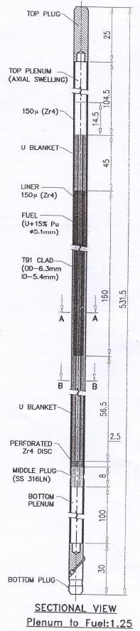
35 Development of high breeding fuels for FBRs Metallic Fuel Pin Design Concepts & Challenges Sodium Bonded Fuel Pin 4.37 T91 CLAD Zr LINER SODIUM FUEL Mechanically Bonded Fuel Pin 5.45 Sodium bonding Suitable for ternerary U-19Pu-6Zr alloy fuel Higher solidus temperature and higher eutectic (with T91) provide better safety margins Lower smear density : higher doubling time Mechanical Bonding Good contact between fuel/ liner/ clad in swaged pin Zr liner inhibits fuel clad chemical interactions Higher smear density 35
36 Fabrication Flow-sheet for Mechanically Bonded Metallic Fuel Charge preparation Groove Making Injection Casting De-moulding Fuel Rod & Blanket Insertion in Zr lined Clad Tube Swaging (Dia. Reduction) Swaging (Mech. Bond) End-Shearing End Plug Welding Length, Weight, Dia. Measurement & ECT Final Inspection Visual, Dimensional & ECT


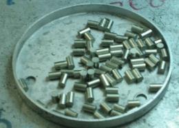
37 Natural U Slug Mechanically Bonded Pins


38 Test Fabrication of Sodium Bonded U-6wt.%Zr fuel Pins Fuel & Blanket: Natural U-6wt%.Zr Slug dimension: 211 mm long, 4.94 mm dia Clad tube and End Plug: T91 Sodium bonding at C Sodium rod extrusion Status U-6%Zr fuel slugs were made in BARC, Trombay Six test fuel pins fabricated in glove box facility at IGCAR The qualified pins were incorporated in two capsules of three pins each The pins, placed in two special subassemblies, are currently undergoing irradiation in FBTR On-going Programme Fabrication of sodium bonded fuel pins with EU(~15%)-6wt.%Zr Clad Fabrication of mechanical bonded fuel pins Fabrication of sodium bonded fuel pins with EU- 19Pu-6Zr Irradiation of above pins is planned to be done in 2013 Argon Atmosphere Glove box Train Slug Sodium Sodium level indication Plenum
 2.Phase transformation 3.Thermal expansion 4.")

39 Metallic fuels: Studies carried out Evaluation of thermo-physical properties 1.Melting point (solidus/liquidus) 2.Phase transformation 3.Thermal expansion 4.Hot hardness 5.Thermal conductivity 6.Thermal cycling Compatibility studies 1. FCCI by diffusion couple 2. Reaction between T-91 and metallic alloys with the help of DSC.


40 Zr liner in binary alloy prevents eutectic formation The effectiveness of Zr liner at 700 o C/1500 hrs U Zr T91 U-Fe Phase diagram Eutectic formation at 735 o C U-Zr Phase diagram No Eutectic formation in U-Zr system
(Fe,Cr) 2 Zr")

41 Diffusion couple experiment between U-Zr alloys and T91 cladding at 700 C for 500 h Zr rich layer (U,Zr)(Fe,Cr) 2 Zr depleted layer T91 Zr depleted layer U-6Zr (U,Zr)(Fe,Cr) 2 Migration of Zr occurs in metallic fuels Zr rich layer T91 U-6Zr T91

42 Zr liner concept in metallic fuels for the binary U-15%Pu alloy U-15Pu Reaction product Zr liner T91 Diffusion couple of U- 15Pu/Zr/T91 annealed at 700 C for 500 h showing effectiveness of Zr barrier in preventing the reaction between the fuel and cladding. Fuel-clad chemical interaction (FCCI) has been recognized as one of the major concerns for metallic fuels because of the formation of low melting eutectic. The formation of eutectic can be avoided by having Zr liner of about 100μm thick in between fuel & clad.


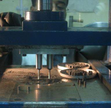
43 METALLIC FUEL FABRICATION AND INSPECTION FACILITY AT BARC DEMOULDING & SHEARING SET-UP AUTOMATED INSPECTION SET- UP INJECTION CASTING SET-UP SWAGING MACHINE
44 CERMET Fuel
 is a ceramic having lower compatibility issues with cladding 3.")
45 CERMET Fuels for Fast reactors Thermal expansion (%) CERMET fuels consist of ceramic fuel particles dispersed PuO 2 particle within a metal matrix. 1. High TC and good thermal shock resistance because of metallic matrix. 2. Fissile component (PuO 2 ) is a ceramic having lower compatibility issues with cladding 3. The MP of U-PuO 2 cermet will be minimum C but could be 100s of degree higher depending on O in solution due to oxygen release during operation/o pickup during fabrication. U/U-Mo matrix Cermet: U-15% UO 2 Cermet: U-30% UO Potential for achieving high breeding ratio though may be 1.0 U -U 1.0 marginally lower than metallic fuel. 0.5 U -U Metallic matrix is a supplementary additional barrier to FGR Yield of cermet fuel manufactured by PM route is much higher compared to melting & casting route used for metallic fuel. Heating rate: 5 0C/min Atmosphere: High purity argon Temperature ( 0 C) Thermal expansion of CERMET fuels 0.0
46 Characterisation & Chemical analysis of U powder U metal powder Sintered UO 2 pellet Crushing in jaw crusher Milling in stirred ball mill for 30 minutes. Characterisation & Chemical Analysis of UO 2 Sieving to obtain 75 to 100 µm size particles Mixing in blender Compaction 900 MPa Sintering at 1075 o C /8hrs Sintered CERMET Pellet Flow sheet for the fabrication of CERMET fuel Compact Linear mass, Chemical Analysis, Visual & Dimensional inspection
 CERMET fuels for Fast Reactors")


47 Thermal Conductivity (W.m -1.K -1 ) CERMET fuels for Fast Reactors Microstructure of U-15%UO 2 CERMET fuel U+ 30%UO 2, 1090 o C, 4hrs, Argon Thermal Conductivity of U-UO 2 CERMET fuel CERMET FUEL U- 15% UO 2 U- 30% UO U+ 30%UO 2, 900 o C, 4hrs, Argon Temperature (K) 47
48 Conclusions Development of Fast Reactor fuels in India started in early Seventies. The successful development of Mixed Carbide fuels for FBTR and MOX fuel for PFBR have given confidence in manufacture of fuels for Fast Reactors. Effort is being put to develop high Breeding Ratio Metallic fuel (binary/ternary). Few fuel pins have been fabricated and is under test irradiation. However, this is only a beginning and complete fuel cycle activities are under development. Metal fuelled Fast Reactors will provide high growth rate in Indian Fast Reactor programme
49 Thank you