Dipl.-Ing. Michael Berger, RHI AG, Vienna and Dipl.-Ing. Jochen Schlüter SMS Mevac GmbH, Essen. Seminar:
|
|
|
- Myles Butler
- 5 years ago
- Views:
Transcription
1 Process Conditions and Factors affecting the Refractory Lining Life and the Development of Refractory Materials Technology in OXYGEN BLOWING CONVERTERS Dipl.-Ing. Michael Berger, RHI AG, Vienna and Dipl.-Ing. Jochen Schlüter SMS Mevac GmbH, Essen Seminar: Refractory Technology Applications, Wear Mechanism, Failures Steel Academy Steel Institute VDEh PO box Düsseldorf Sohnstraße Düsseldorf Germany Fon Fax Internet:
2 Process Sequence and Variables affecting the Durability of Converters and the Development of the Refractory Materials Technology in BOF s Jochen Schlüter Sales Director SMS Mevac, Essen Michael M. Berger Area Sales Manager Senior Process Specialist Steel RHI AG, Vienna 11 Refractory Technology: Part II Introduction Process description: Combined blowing Charge materials Process sequence 1. Places of reaction 2. Reactions 3. Process control / process models Trends in BOF technology Detection of wear areas Wear areas inside the converter Stirring in the converter Tapping Maintenance and care Development results concerning refractory technology Wear mechanisms and actions Chamber of horrors 22

3 Annual Steel Production - Worldwide Mio t Year 3 Crude-Steel Production BOF - EAF 44

4 Development of Oxygen Steelmaking Processes 55 Refractory Technology: Part II Introduction Process description: Combined blowing Charge materials Process sequence 1. Places of reaction 2. Reactions 3. Process control / process models Trends in BOF technology Detection of wear areas Wear areas inside the converter Stirring in the converter Tapping Maintenance and care Development results concerning refractory technology Wear mechanisms and actions Chamber of horrors 66


5 BOF in Blowing Position 77 Layout of Basic Oxygen Furnace down shaft Additives bunker O 2 Lance Gas cooling hood Trunnion ring Top cone Cylinder Tilting drive Bottom cone Stirring gases Ar, N 2 Bottom 88

6 Sectional View of Oxygen Blowing Lance 99 Refractory Technology: Part II Introduction Process description: Combined blowing Charge materials Process sequence 1. Places of reaction 2. Reactions 3. Process control / process models Trends in BOF technology Detection of wear areas Wear areas inside the converter Stirring in the converter Tapping Maintenance and care Development results concerning refractory technology Wear mechanisms and actions Chamber of horrors 10
7 Scrap Charging 11 Table of Scrap Grades Category Grade no. Grade description Old scrap B3 Heavy steel scrap, predominantly thicker than 6mm, prepared suitable for charging, may contain pipes and hollow sections. No automotive body scrap and no car wheels. Free from visible Cu, Sn, Pb and alloys and debris. E1 Lightweight steel scrap, predominantly less than 6mm, prepared suitable for charging, may contain car wheels, but must exclude automotive body scrap and domestic appliance scrap. Free from visible Cu, Sn, Pb and alloys and debris. New scrap E2 Heavy new steel scrap, predominantly thicker than 3mm, prepared suitable for charging. The steel scrap must be free from coatings and concrete reinforcing bars and steel bars, also from new productions. Free from visible Cu, Sn, Pb and alloys and debris. E8 Lightweight steel scrap, predominantly less than 3mm thick, prepared suitable for charging. The steel scrap must be free from coatings and loose steel strip to avoid problems during charging. Free from visible Cu, Sn, Pb and alloys and debris. E6 Lightweight steel scrap (less than 3mm thick), compacted or in the form of compressed packages, prepared suitable for charging. The steel scrap must be free from coatings. Free from visible Cu, Sn, Pb and alloys and debris. Shredded scrap E40 Old steel scrap cut into pieces which in no case are allowed to be bigger than 200mm for 95% of the charge. The remaining 5% must not contain pieces of more than 1000mm, prepared suitable for charging. The scrap should be free from severe humidity, loose cast-iron pieces and waste incineration scrap (in particular tin-plated beverage cans). Free from visible Cu, Sn, Pb and alloys and debris. Steel chips E5H Homogeneous batches of carbon steel chips, free from excessive amounts of woolly chips, prepared suitable for charging. Chips of free-cutting steel must be clearly identified. They must be free from impurities such as nonferrous metals, scale, grinding dust and the like. Lightweight alloyed scrap Scrap with high share of residues Waste incineration scrap E5M EHRB EHRM E46 Mixed batches of carbon steel chips, free from excessive amounts of woolly chips, loose material and free-cutting steel chips, prepared suitable for charging. They must be free from impurities such as nonferrous metals, scale, grinding dust and the like. Old and new steel scrap which consists predominantly of concrete reinforcing bars and lightweight steel, prepared suitable for charging. Must be free from visible Cu, Sn, Pn, alloys and debris. Old and new machine parts and components which are not accepted in the other grades, prepared suitable for charging. May contain cast-iron pieces (housing components). Must be free from visible Cu, Sn, Pb, alloys and parts from ballbearing housings, bronze race rings and other grades and debris. Shredded scrap from waste incineration plants. Loose steel scrap from domestic waste which has been processed by a magnetic separation plant, prepared suitable for charging. Must be free from visible Cu, Sn, Pb, alloys and debris. 12
8 Hot Metal Charging 13 Hot Metal Hot metal analysis: C : % Si : % Mn : % P : % S : % Temperature: C 14
9 Fluxes and Additives Slag formers: Coolants: Heating agents: - Lime - Dolomite lime - MgO carriers - Ore, pellets - Dust briquettes - Cooling scrap -FeSi -Coke Alloying agents: - Copper - Nickel - Molybdenum 15 Refractory Technology: Part II Introduction Process description: Combined blowing Charge materials Process sequence 1. Places of reaction 2. Reactions 3. Process control / process models Trends in BOF technology Detection of wear areas Wear areas inside the converter Stirring in the converter Tapping Maintenance and care Development results concerning refractory technology Wear mechanisms and actions Chamber of horrors 16


10 BOF - Schematic Model red/brown smoke oxygen lance sprayed iron-drops lancing channel foamed slag iron-drops CO-bubbles melt fire spot source: dept. of metallurgy RWTH Aachen 17 Reaction Products (minor desulphurization) Reaction product slag gas phase gas phase slag slag slag slag Reactions inside the converter are exothermal Control of heat balance ===> Scrap charging 18


11 Diagram - Melting Losses 19 Binary System Diagram CaO / FeO 20
12 Diagram - Melting Losses Start range Main decarburization phase Final blowing phase 21 Crude Steel / Slag Analysis Crude - steel analysis C : 0,02 0,03 % Si : 0 Mn : 0,1 0,2 % P : 0,01 0,02 % S : 0,01 0,05 % (HM-desulphurization) Oxygen : ppm Temperature: C Slag analysis FeO : % CaO : % SiO 2 : % MnO : 3 4 % Al 2 O 3 : 1 2 % MgO : 2 4 % P 2 O 5 : 1,3 1,5 % (S) : 0,1 0,2 % Basicity (CaO + MgO / SiO 2 ): 3 4 Slag volumes kg/t 22
13 BOF Process Models Hot metal Scrap static model Process computer dynamic model Temperature 23 Model - Charged Material Order calculation (scheduled data) Slag model (Fe) content Basicity Heat balance model Hot metal Scrap Lime Correcting calculation (real data) Heat balance model Blowing oxygen Lime Coolant 24
14 Model Sublance Measurement / End Blow aimed - phosphorus content RHI-Folie temperature [ C] cooling heating end blow Oxygen [Nm³] Volume of Oxygen to adjust the P- content and the steel temperature after sublance measurement 25 Temperature Increase vs. O 2 Volume Blown Temperature in [ C] Oxygen flow-rate in [Nm³] (STP) Increasing steel temperature as a function of blowing oxygen after sublance measurement 26
15 End blow Fe-content as a function of Sublance Measurement Steel temperature: 1,680-1,720 C Lime: 9,150 kg (Fe) content in [%] End-blow temperature C] 27 Influence - Tapping Temperature on P-Content Final phosphorous content in 10-3 [%] tapping temperature P-content of melt in 10-3 [%] 28
16 Influence - Metallurgy on Refractory Lining Si, P, Mn C P, Temp. (C2S/C3S) (C3P/C4P) CaO <- (FeO) (FeO) + C -> Fe + CO Refractory wear CaO + FeO => (P 2 O 5 ) Proper de-phoshorization requires low temperatures However, a high temperature is needed at the end of blowing Fe + 1/2 O2 -> FeO Temp. low Temp. increasing Temp. high 29 Refractory Technology: Part II Introduction Process description: Combined blowing Charge materials Process sequence 1. Places of reaction 2. Reactions 3. Process control / process models Trends in BOF technology Detection of wear areas Wear areas inside the converter Stirring in the converter Tapping Maintenance and care Development results concerning refractory technology Wear mechanisms and actions Chamber of horrors 30

17 BOF trends Influences on Refractories 31 Refractory Technology: Part II Introduction Process description: Combined blowing Charge materials Process sequence 1. Places of reaction 2. Reactions 3. Process control / process models Trends in BOF technology Detection of wear areas Wear areas inside the converter Stirring in the converter Tapping Maintenance and care Development results concerning refractory technology Wear mechanisms and actions Chamber of horrors 32


18 BOF Pre-wear Areas - schematic A - Hot metal impact D - slag zone de-slagging position B - Scrap impact E - slag zone tapping position C - slag zone upright vessel F - bottom joint 33 34


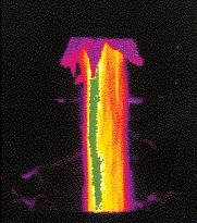
19 Laser Scan Measuring the Residual Thickness 35 Laser Scan BOF Lining Pre-wear in slag zone and tapping breast 36


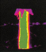
20 37 Laser Scan BOF Bottom 2184 heats 38

21 Laser Scan BOF Bottom 2144 heats 39 Pre-wear areas - BOF scrap impact 40
22 Pre-wear areas - BOF scrap impact trunnion 41 Pre-wear areas - BOF slag lines scrap impact trunnion 42


23 BOF Slag Lines 43 Pre-wear areas - BOF slag lines scrap impact trunnion bottom, bottom joint and bottom cone 44


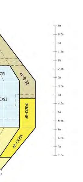
24 45 Bottom Lining Concepts Installation without bottom joint nonremovable bottom installation with bottom joint, removable bottom radial keys radial installation, without bottom joint system end arch brick, incl. bottom joint 46
 radial (fully inclined) concept 47 BOF Installation Mixes Requirement Type Backfill mixes (dry) Ramming mix (light moist) storage life free flowing (dry")
 + combination sinter type Bottom joint mix storage life good compressibility high stability after coking high refractoriness C-content sinter")
25 Bottom / Bottom Joint Design Solutions radial bottom with horizontal side wall bricks: keys end arches radial bottom, defined bottom joint (here labyrinth joint and filler bricks) radial (fully inclined) concept 47 BOF Installation Mixes Requirement Type Backfill mixes (dry) Ramming mix (light moist) storage life free flowing (dry mixes) good compressibility for dry mixes stability of shape quick and reliable drying for ramming mixes backfill mixes only sinter (no bonding) ramming mixes (sulphate, phosphate, borate, chromate) + combination sinter type Bottom joint mix storage life good compressibility high stability after coking high refractoriness C-content sinter type 48
26 Pre-wear areas - BOF mouth, upper cone slag lines scrap impact trunnion bottom, bottom joint and bottom cone 49 BOF - Optimised Lining Concepts standard optimised Lining thickness - brick length: effective thickness: 690 mm nominal brick length: standard: 600 mm inclined: 550 mm plus decreased steps: 60 mm to 35 mm Internal force progression: standard: shear stresses into the neighbouring brickwork (vertical expansion inserts) inclined: following the vessel contour less expansion inserts! 50


27 BOF - Collapsed Upper Cone 51 52


28 Development of Lining Concepts - I late 1980 s mid 1990 s Development of Lining Concepts - II Example of a modern BOF lining concept 2010/11 54

29 New Installed Lining 55 Refractory Technology: Part II Introduction Process description: Combined blowing Charge materials Process sequence 1. Places of reaction 2. Reactions 3. Process control / process models Trends in BOF technology Detection of wear areas Wear areas inside the converter Stirring in the converter Tapping Maintenance and care Development results concerning refractory technology Wear mechanisms and actions Chamber of horrors 56
30 Pre-wear areas - BOF mouth, upper cone slag lines scrap impact trunnion Stirring / purging elements bottom, bottom joint and bottom cone 57 Requirements of BOF Purging Elements Permeability spezific flow rate 0,01-0,25 Nm³/t, min flow rate per element up to >100 Nm³/h maximum gas pressure 8-18 bar Fully functional with low flow rates pgas > p ferrostatic ability to start after gas flow interruptions Wear rate of the elements should correspond to the wear rate of the bottom constant flow rate independent of the length of the element Safety against breakouts - in case of abrupt unforeseen loss of gas flow and pressure 58
 59 Types of Purging Elements -")


31 Types of Purging Elements - I Purging element: MHP- (Multi Hole Plug) purg plug Single hole purge plug (tuyere) 59 Types of Purging Elements - II trends: goal: - BOF bottom stirring is standard in Europe and Japan - North America, trend of using bottom purging is increasing - Requirement to purge until end of vessel campaign hydraulically pressed Isostatic pressed pitch-bonded resin-bonded Fused MgO high grade % C resin-bonded 60
32 Gas Bubble Formation BLASENGASEN einzelne Blasen GAS BUBBLING transition zone STRAHLGASE JET N Blasenschwarm BUBBLING Blasenbildungsfrequenz bubble building bubble volume Blasenvolumen gas volume 61 Refractory Technology: Part II Introduction Process description: Combined blowing Charge materials Process sequence 1. Places of reaction 2. Reactions 3. Process control / process models Trends in BOF technology Detection of wear areas Wear areas inside the converter Stirring in the converter Tapping Maintenance and care Development results concerning refractory technology Wear mechanisms and actions Chamber of horrors 62
33 Pre-wear areas - BOF mouth, upper cone slag lines scrap impact trunnion taphole stirring / purging elements bottom, bottom joint and bottom cone 63 BOF Taphole - Requirements Requirements Turbulence free tapping Compact tapping stream target - Lowest possible reaction with the atmosphere (air) - Minimized Reoxidation and N2 pick-up - Reduced amount of carry over slag into the ladle during tapping Optimised preconditions for slag detection as well as prevention Constant tapping times High taphole lives Easy and quick repair - Lowest possible carry over slag at the end of tapping therefore - Reduced demand of alloys, saving of alloys due to reducted reoxitation - Even tapping conditions - Increased availability of the vessel - High availability, - Minimised manual work; safety issue Prevention of steel infiltrations Minimised risk of breakouts in the taphole area High system security 64


34 BOF Taphole design solutions Pipe in pipe system Isojet C system Taphole block Taphole repair sets 65 BOF Taphole - design 66

35 BOF Taphole - design Standard channel layout Optimised channel layout 67 BOF - taphole 68


36 69 Slag detection - AMEPA 70


37 Slag detection optical 71 Slag detection - optical 72


38 Slag prevention Slag dart Slag ball Slide gate PSS pneumatic hammer 11 Refractory Technology: Part II Introduction Process description: Combined blowing Charge materials Process sequence 1. Places of reaction 2. Reactions 3. Process control / process models Trends in BOF technology Detection of wear areas Wear areas inside the converter Stirring in the converter Tapping Maintenance and care Development results concerning refractory technology Wear mechanisms and actions Chamber of horrors 22

 storage life quick flowing no formation of lumps quick coking time stability")
39 TBD Taphole Changing Unit Removing the worn taphole sleeves by means of counter percussion hammering system Calibrating the taphole channel 33 BOF Repair Mixes Requirements Type Gunning mixes storage life applicable with spraying machines no / little rebound low formation of dust bond durability bonding system Phosphate Silikat - glas sinter Hot repair mixes (C-containing) storage life quick flowing no formation of lumps quick coking time stability sinter 44


40 Schematic BOF gunning / spraying wet fines deformation and build up coarse grain slowing down and embedding Impact velocity: v = m/s gunning bed gunning layer 55 BOF gunning / spraying machines Shooter mobile gunning unit Pressure vessel machine to feed the spraying unit (ANKERJET) 66


41 BOF gunning / spraying machines Conrep gunning Robot 77 BOF gunning / spraying machines Conrep gunning result 88


42 BOF gunning / spraying Flow rate effects on gunned refractory layer Increasing flow rate Legend: BD: bulk density OP: open porosity Porous area Porous area grain High BD rate means more material in equal gunning mix thickness resulting in longer chemical resistance. Low OP rate means less slag infiltration and therewith higher lifetime and improved anti-wash-out effect (mechanical erosion). 99 Slag splashing Slag coating Slag Refractory lining 10

43 BOF - maintenance overview 11 Refractory Technology: Part II Introduction Process description: Combined blowing Charge materials Process sequence 1. Places of reaction 2. Reactions 3. Process control / process models Trends in BOF technology Detection of wear areas Wear areas inside the converter Stirring in the converter Tapping Maintenance and care Development results concerning refractory technology Wear mechanisms and actions Chamber of horrors 12
44 BOF Operating Conditions in Various Regions Europe North America Japan Productivity high, heats/day low, heats/day high heats/day Slag splashing increasing Standard (Slag splashing) little Tapping temp C C C Slag formation MgO [%] w/o dolo-lime: 2-5 Dolo-lime: 8-14 "low slag operation" Hot metal, Si (%) < 0,7 < 0,8 < 0,3 HM de-phosph. no no yes Scrap charge (%) < 20 < 30-5 Bottom stirring (%) Avg. lives (heats) , max max max Trend - Refractory Consumption in Europe 5 amount of refracrory material [kg / t] 4,5 4 3,5 3 2,5 2 1,5 1 0,5 0 Mixes MgO-C MgO MgO&MgO-C Dolomite-MgO Dolomite year 14

45 Refractory Technology: Part II Introduction Process description: Combined blowing Charge materials Process sequence 1. Places of reaction 2. Reactions 3. Process control / process models Trends in BOF technology Detection of wear areas Wear areas inside the converter Stirring in the converter Tapping Maintenance and care Development results concerning refractory technology Wear mechanisms and actions Chamber of horrors 15 16
46 Requirements - MgO C bricks Operational demand (= pre wear mechanism) Erosion continuous wear (erosive brick wear) Erosion resistance Required brick properties (= measures) 17 Requirements - MgO C bricks Erosion resistance Required brick properties (= measures) 2. C- content Bonding system Antioxidants MgO 18
 + Temperature, FeO 2. 4.")
47 19 Requirements - MgO C bricks Operational demand (= pre wear mechanism) Erosion Slag attack continuous wear (erosive brick wear) + Temperature, FeO Erosion resistance Corrosion resistance Required brick properties (= measures)) 20
 liq.")
48 Requirements - MgO C bricks Erosion resistance Corrosion resistance Required brick properties (= measures) C-content Bonding system Antioxidants MgO Periclas + xx 21 Infiltration Prevention Reduction of Iron-oxids of the infiltrated media (CaO-FeO x SiO 2 ) liq. + CO [CaO-SiO2] solid + Fe met + CO 2 eutectic C eutectic >1650 C Non-wettability of the infiltrated media (with CaO/SiO2<2) MgO Carbon 22
 + Temperature, FeO 2. 3. 4.")
49 Wear Mechanism of MgO C Bricks slag coating De-carburization Partly De-carburized (Binder) 23 Requirements - MgO C bricks Operational demand (= pre wear mechanism) Erosion Oxidation Slag attack continuous wear (erosive brick wear) + Temperature, FeO Erosion resistance Oxidation as well as Redox resistance Corrosion resistance Required brick properties (= measures) 24
 2. 3. 4.")
50 Requirements - MgO C bricks Erosion resistance Oxidation as well as Redox resistance Corrosion resistance Required brick properties (= measures) C-content Bonding system Antioxidants MgO Pitch Periclas xx Periclas xx 25 26

51 27 Requirements - MgO C bricks Operational demand (= pre wear mechanism) Erosion Oxidation Slag attack continuous wear (erosive brick wear) + Temperature Erosion resistance Oxidation as well as Redox resistance Corrosion resistance Required brick properties (= measures) 28
 2. 3. 4.")
52 Requirements - MgO C bricks Erosion resistance Oxidation as well as Redox resistance Corrosion resistance Required brick properties (= measures) C-content Bonding system Antioxidants MgO Pitch Periclas xx Periclas xx 29 30
 1. 2. 3. 4.")
 lower high Strength")
53 Requirements - MgO C bricks Flexibility of the structure Erosion resistance Oxidation as well as Redox resistance Corrosion resistance Required brick properties (= measures) C-content Bonding system Antioxidants Pitch Pitch MgO Periclas xx Periclas xx 31 Pitch vs. Resin bonding Pitch bonding Resin bonding C-content high lower Graphitising high lower Strength (original) lower high Strength (after coking) high lower (without Antiox.) Porosity (after coking) lower higher (without Antiox.) Flexibility high lower 32

54 33 Refractory Technology: Part II Introduction Process description: Combined blowing Charge materials Process sequence 1. Places of reaction 2. Reactions 3. Process control / process models Trends in BOF technology Detection of wear areas Wear areas inside the converter Stirring in the converter Tapping Maintenance and care Development results concerning refractory technology Wear mechanism and actions Chamber of horrors 34

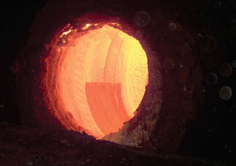
55 Refractory Technology: Part II wear cases... have a guess!! 35 36
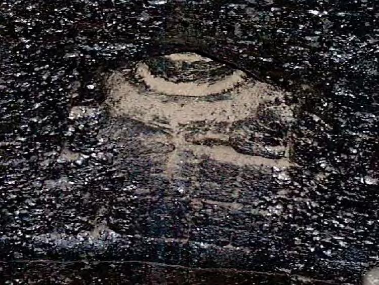
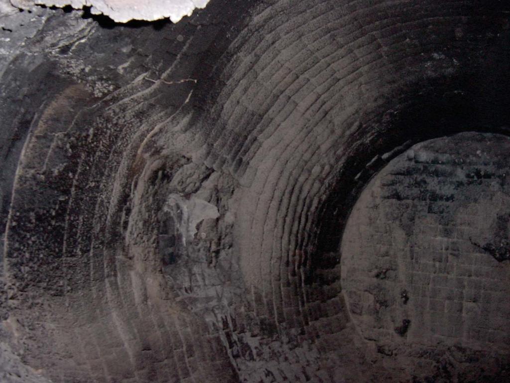
56 37 38


57 39 40

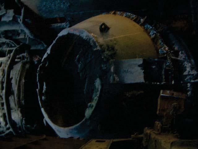
58 41