SiC crystal growth from vapor
|
|
|
- Clement Walker
- 5 years ago
- Views:
Transcription
1 SiC crystal growth from vapor Because SiC dissolves in Si and other metals can be grown from melt-solutions: Liquid phase epitaxy (LPE) Solubility of C in liquid Si is 0.029% at 1700oC high T process; container material, tightness, heating, purity issues 1

2 SiC vapor pressure SiC readily sublimes physical vapor growth can be easily adopted; this is the main technique for large (up to 4 inch) boule growth. SiC sublimes incongruently: Si, Si 2 C, SiC 2, SiC, C the first three species have the highest vapor pressure, they are important for growth the total pressure reaches 10-2 bar at 2400oC accessible conditions for growth 2
3 SiC growth geometry T 2 Thermal Insulation Graphite lid Graphite crucible Seed Crystal Source Material RF Coil Quartz Tube Transport of source material to growing crystal via vapor phase by shifting solid-vapor equilibrium along a temperature gradient T 1 T 1 >T 2 RF heating and a movable coil to change the T-gradient 3
4 SiC growth parameters T 2 T 1 Thermal Insulation Graphite lid Graphite crucible Seed Crystal Source Material RF Coil Quartz Tube T = C P = 5-30 mbar Ar-gas ambient; role of Ar? Seeds SiC single crystal wafers Source SiC powder Source to seed distance, L ~ 1-5 cm T difference, T ~ o C T 1 >T 2 4

5 SiC vapor fluxes 5
6 Sub processes and control sublimation of the source material (source heating) nucleation on the seed (supersaturation and surface kinetics!) crystal feeding (mass transport!) boule growth (temperature distribution!) Mass transport aspect of vapor growth is most difficult to control The phenomena involved are very complex and strongly depend on the geometry of the system A number of parameters to be controlled sublimation, mass transport, nucleation, Si/C ratio, uniformity of supersaturation, surface kinetics, etc. Growth rate ~ T/( L.P Ar ) Diffusion limited Schematic representation of the processes involved in growth of SiC crystals form vapor phase 6

7 Input vs. output parameters Growth T growth rate, polytype T-gradient growth rate, crystal quality Pressure growth rate, purity Source to seed distance growth rate, crystal length Heating of the source growth rate, growth front Seed type and quality polytype, crystal quality Schematic representation of the processes involved in growth of SiC crystals form vapor phase sublimation, mass transport, nucleation, crystal growth. 7
8 Growth rate vs. temperature The growth rate exponentially increases with growth temperature An apparent activation energy of the growth process can be derived from the slope This activation energy is consistent with the activation energy of SiC sublimation (enthalpy of sublimation 148 kcal/mole) The growth process is not limited by the sublimation of the source Arrhenius plot of growth rate; Measurements are done at 5 mbar Ar pressure and source to seed distance 5mm. 8


9 Growth rate vs. pressure With decreasing pressure growth rate increases and tends to saturate below 2 mbar. Such behavior is commonly observed and it is consistent with the pressure dependence of the molecular diffusion coefficient inversely proportional within some range where molecular collisions take place. The region of pressure where the growth rate does not vary is relevant to collision free molecular transport this may be interesting for the practice, but other problems may appear, e.g. vapor composition control Growth of SiC bulk crystals is always done in diffusion limited region Dependence of the growth rate of SiC on the inert gas (Ar) pressure at 2450 o C and source to seed distance 10 mm. 9


10 Growth rate vs. distance The growth rate has a linear dependence on the inverse distance in a broad temperature range oC it is shown by the theory that such a dependence is true for diffusion mass transport R ~ T/( L.P Ar ) Growth rate vs. source to seed distance for three different temperatures, at 5 mbar Ar pressure 10


11 SiC Growth Modes 2D nucleation Spiral growth Typical growth patterns in spiral mode: C- and Si face (from left to right) 11
![SiC crystal structure Hexagonal structure (close packed) Two lattice constants: a and c Polar faces in [0001] Possibility of different stacking order along c- axis more than 200 polytypes](/docs-images/90/103466843/images/12-0.jpg "Most important polytypes: 4H, 6H and 3C Vicinal surface is obtained by a small (several degrees) miscut towards [11-20] (11-20) plane is the most dense more kinks will be available for")
12 SiC crystal structure Hexagonal structure (close packed) Two lattice constants: a and c Polar faces in [0001] Possibility of different stacking order along c- axis more than 200 polytypes Most important polytypes: 4H, 6H and 3C Vicinal surface is obtained by a small (several degrees) miscut towards [11-20] (11-20) plane is the most dense more kinks will be available for growth 12

13 Vicinal surfaces How to produce them? Schematic of a crystal with atomic layers In SiC these are bilayers Si-C, because the bond between Si and C atoms is very strong If the crystal is sliced perpendicularly to the c- axis obtained wafers are called on-oriented and they will not contain regular steps, they will have few steps and large terraces. When the crystal is sliced under some angle in respect to the c-axis obtained wafers will contain regular steps on these vicinal surfaces (off-axis wafers) 13

 cubic (3C)")

14 Growth on well oriented and vicinal surfaces (i) Growth on singular surfaces 2D-nucleation Growth on vicinal surfaces step flow mode For SiC : if growth is performed on large terraces (singular face) cubic (3C) phase may appear and even twins are formed because two stacking orders are possible crucial for epitaxy (low temperature) 14
 The step height of many steps is 1.5nm, i.e. 6 times the Si-C bilayer => the unit c lattice parameter of 6H-SiC.")
15 Growth of SiC on vicinal surfaces Growth on vicinal surfaces step flow mode and micro-step bunching a) AFM image from 6H-SiC (000-1)C surface b) The possible terraces on 6H-SiC (0001) c) The energetically favoured unit cell height step The steps are highly regular, straight and uniformly distributed (a) The step height of many steps is 1.5nm, i.e. 6 times the Si-C bilayer => the unit c lattice parameter of 6H-SiC. This is related to minimization of the surface free energy during crystal growth. The surface energies for each SiC bilayer plane are different due to the stacking sequence of the polytype (b). A particular terrace with the lowest energy dominates the surface and the possible step bunching in 6H-SiC is the formation of 3 bilayer height steps (ABC or ACB layer steps in 6H-SiC). 15


 Micropipe along the c-axis In the middle of a spiral")
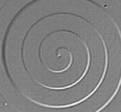
16 Spiral Growth of SiC and defects Most common on well oriented substrates requires the lowest supersaturation In this mode continuous growth occurs during which screw dislocation is persistent in the middle of the spiral. If the dislocation in the seed crystal are many, they may interact as the growth proceeds strain energy will be accumulated and above certain value of the Burgers vector a hollow core dislocation will be formed, called micropipe. Micropipes can be observed in the middle of spirals, or after chemical etching (molten KOH for SiC) Micropipe along the c-axis In the middle of a spiral After hot KOH etching 16


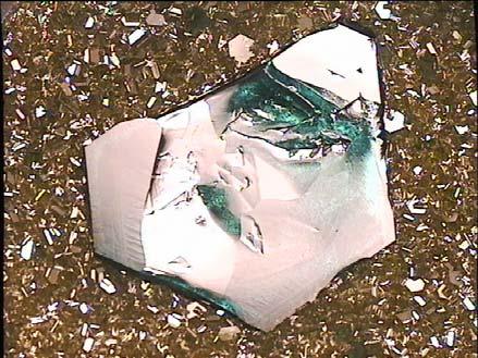
17 SiC commercial wafers Seeded Sublimation Growth (SSG) most developed for SiC growth 100mm wafers on the market Growth from vapor phase more difficult to control in respect to growth rate, crystal size, and structural defects increased prime cost 4H-SiC, commercial wafer SI P-type N-type 17
 has some advantages ( as compared to melt growth) => (i) lower processing temperature; (ii) purification effect")
18 Vapor growth of II-VI semiconductors II-VI => ZnSe, CdTe, ZnO, etc. For these materials crystallization from vapor phase by physical vapor transport (PVT) has some advantages ( as compared to melt growth) => (i) lower processing temperature; (ii) purification effect as a result of the difference in the vapor pressures of the native elements and the impurities; (iii) higher interfacial morphological stability of the solid-vapor interfaces. In the PVT, the species found in the vapor phase => Zn or Cd (II group) and diatomic molecules of group VI elements (O 2, S 2, Se 2, or Te 2 ). The transport rate is controlled => by the temperature of the source, the partial pressure of the species (II and VI 2 ) and the enclosed gas pressure. Note*: the partial pressure of the components can vary by orders of magnitude as the composition of the compound varies over the homogeneity range => stoichiometry control important Sizable crystals of high quality can be obtained => e.g. ZnSe crystals mm in diameter. 18
19 Free-growth method Markov-Davydov technique or seeded PVT (SPTV) => closed system Polycrystalline source => put in a chamber with perforated walls in the upper part of the ampoule A seed crystal => placed below at a definite distance on the center of a quartz or sapphire pedestal The total pressure in the ampoule => 1 atm H 2 or mixture with Ar => residual atmosphere in sealed ampoules; Source T ~1200 o C, seed T ~1165 o C In a horizontal system with double seeds at the ends and source in the middle up to 2inch diam. and 25 mm length obtained by Eagle-Picher Industries. Tsource ~1200 o C and the difference with the crystal < 100 o C. 19
20 Semi-open growth systems The source is loaded in an ampoule, in which a vent hole of 1-2mm is made The ampoule is placed in an outer quartz tube, which is sealed off at one end and connected to a vacuum pump and an Ar supply connected in parallel => Ar has been shown to make the leakage of the excess component from the growth zone controllable. The residual Ar pressure is adjusted to a value allowing congruent sublimation. Three zone resistance heated furnace, T is controlled in each zone by thermocouples. 20
21 CVT method Chemical vapor transport (CVT) => iodine is widely used as the chemical agent, allows crystal growth at temperatures far below transition temperatures (melt and vapor). The principle => seed and source are placed at the ends of a closed quartz ampoules together with calculated amount of iodine. The role of the iodine is to react with the source material ( e.g. ZnSe) and to transport it to the seed, where the compound will decompose and ZnSe will be released on the seed ( Iodine => transport agent) Since iodine is not consumed by the crystal its amount can be calculated and related to the growth time. The partial pressure of different components present inside the ZnSe-I 2 system during CVT growth of ZnSe single crystals is calculated assuming mass conservation of iodine. => Using the partial pressure of different components inside the ampoule the optimum growth conditions for the growth of good quality ZnSe single crystals can be predicted theoretically. The growth rate is very low, the process takes place for several days. Essential problem is the convective transport, it has to be decreased to maintain stable growth conditions and crystal morphology. The quality of the crystals is very good, but the size is rather small 21


22 CVT grown crystals Small crystal (earlier) Recently 1inch in diameter ZnSe crystals => grown Polished wafer from 1 crystal Schematic illustration of the ampoules. Two types of ampoules (type 1 and type 2) are prepared. θ indicates the angle at the conical tip. After loading with all materials, the ampoule is evacuated to a pressure 3x10⁻⁷ Torr. When the ampoules are heated up, the pressure will increase => the total pressure and the sum of the partial pressures of the reaction species are important for the growth rate and the morphological stability of the crystals. 22
, which enables growth of single crystals and high growth rate, is around 850 o C")
23 CVT growth of ZnSe Basic reactions: Effect of growth temperature The optimum growth T (seed), which enables growth of single crystals and high growth rate, is around 850 o C 23
 => thermal convection prevails at high pressure.")
24 Effect of iodine concentration Total pressure is considered > equivalent to the iodine concentration Increase of the growth rate in region C is related to convective mass transport ( assuming mass transport limits the growth rate) => thermal convection prevails at high pressure. Generally, the convective transport causes random nucleation at the growth front resulting in twin boundaries, voids and even polycrystalline material => significant contribution of convective mass transport should be avoided in CVT of ZnSe. The increase of the growth rate in region A => not well explained. The optimum iodine concentration should be situated in region B from the view point of morphological stability and high growth rate. Other optimum conditions: T>85OoC; seed orientation = (l 11 )B, angle of the conical tip => 30 ; iodine concentration => 1.1 mg/cm3. 24