CRYOGENIC MATERIAL TESTING
|
|
|
- Roy Poole
- 5 years ago
- Views:
Transcription


1 Christoph Zauner CRYOGENIC MATERIAL TESTING SPECIAL REQUIREMENTS FOR TEST SETUP AND TEST PERFORMANCE DEMONSTRATED ON ADDITIVE MANUFACTURED LIGHTWEIGHT ALLOYS
2 Index Demand of cryogenic testing Cryogenic temperature ranges and cooling methods Building cryogenic test setups Material Design Performing cryogenic tests Example(s)
3 Demand on cryogenic testing Space: liquid propellant tank structures (20K for LH) cryogenic instruments Fusion Research: superconducting magnet structures (4K) Automotive liquid hydrogen tank structures Goal: material characterisation component / structure verification

 direct immersion in liquid nitrogen test")
 direct immersion in liquid helium")
4 Temperatures and cooling methods Overview on typical temperature ranges, cooling methods and cooling equipment Temperature Method Equipment hot to -140 C (-180 C) evaporative cooling of liquid nitrogen thermal chamber -196 C (77K) direct immersion in liquid nitrogen test dewar -196 C to -263 C (10K) evaporative cooling of liquid helium helium dewar gas phase -269 C (4K) direct immersion in liquid helium helium dewar liquid phase
5 Cooling Fluids Comparison of Nitrogen and Helium Temperature Nitrogen Helium Ratio He / N2 Temperature -196 C / 77K -263 C / 4K - Density liquid in kg/l 0,8076 0,1785 0,22 Heat of vaporisation in kj/kg ,1 0,11 Cost per liter in 0, Cost per cooling 1kg stainless steel to liquid temperature in Delivery Gas recoverage 0, by truck stored in big tanks not required On-site helium liquefier strongly recommended
 + - Wide")


6 Thermal chamber (RT to -140 C) + - Wide temperature range, and integrated easy control Feedthrough of fixed and moving test machine interface Limited cryogenic range (commercial -140 C, self build to -180 C)


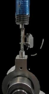
7 Direct immersion in liquid nitrogen + - High cooling rate Flexible cryostat design Fixed temperature Risk of thermoelastic damage of the test setup / test machine during cooling down


8 Evaporation of liquid helium + Wide temperature range (77K to ~10K) - Temperature gradient along specimen needs to be compensated by electrical heating Low cooling rate High Cost Temperature Control and LHe flow control required


9 Direct immersion in liquid helium + - Lowest cryo-temperature Fixed temperature Risk of thermoelastic damage during cooling down High cost Baffle system required
10 Cryogenic test setups - Materials Stainless steel is mainly used Low embrittlement and thus robust against transient forces during specimen failure Low thermal conductivity (good isolation of load bearing parts)


11 Cryogenic test setups - Design guidelines Mechanical design mass is money at LHe! FEM to identify load paths and optimize w.r.t. mass (morphological optimization) Assess maximum load capacity of test setup at different temperatures (w.r.t. temperature depended yield strength) Take care not to overload stainless steel setups at RT or high temperature
12 Cryogenic test setups - Design guidelines Thermal design FEM to identify temperature distribution and achievement Evaluate cooling time and cost per test


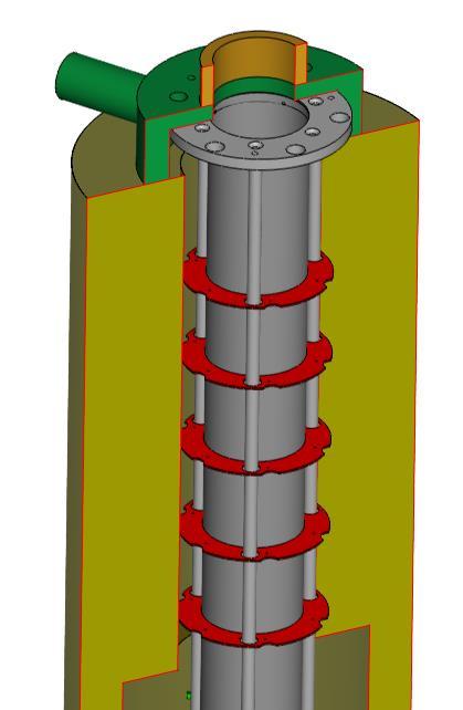
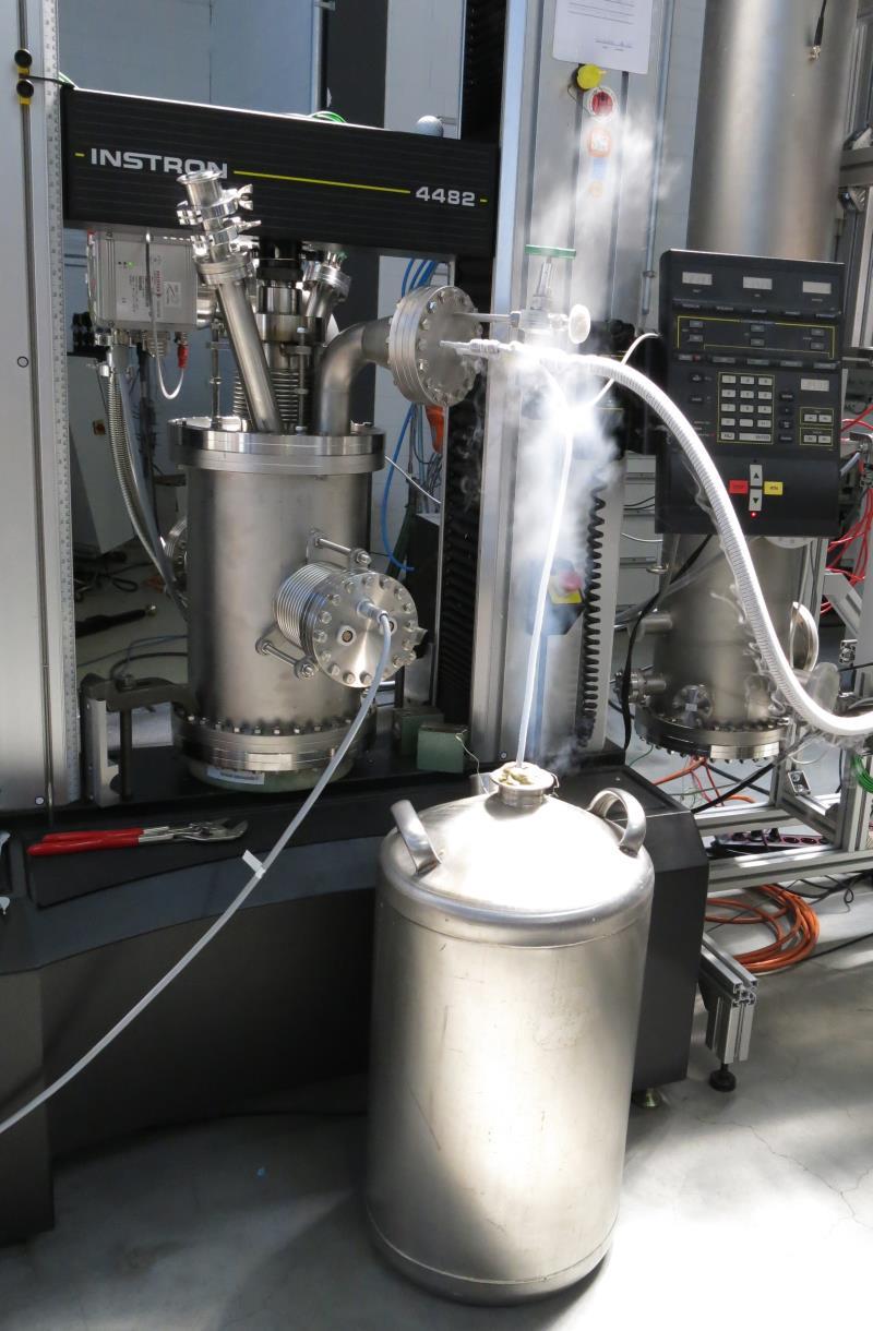
13 Cryogenic setups Vacuum environment Low convective heat transfer Two axis friction test 2MN/2MN at -190 C under vacuum vacuum sealing in cryogenic temperature: CF flanges Internal and external cooling of load bearing paths Heat transfer coefficient from 150 C to 250 C at 50kN LN2 tank mobile 100l LN2 tank fixed 4200l LN2 indirect cooling vacuum chamber LN2 N2 direct cooling channels NSE Interface LN2-outlet


14 Cryogenic test performance Select temperature compatible strain gauges, extensometers and temperature sensors Protect test machine from condensed water Monitor oxygen in test lab Take into account liquid oxygen and liquid hydrogen Provide gaps for different thermal expansions Don t block test machine during cooling down and heating up high risk of overload and destruction Stiffness Temperature CTE Vetronit Isolation Protective Foil


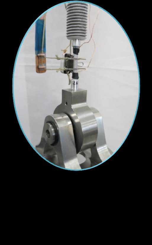

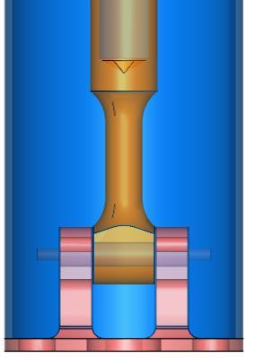

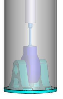
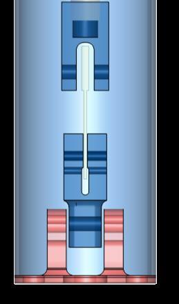
15 Application example 3D printed metals Test setup design Tension Compression Shear Pin Bearing


")
16 Application example 3D printed metals Temperature levels RT 200K (-73 C) 77K (-196 C) 4K (-269 C)
17 Strain rate [s-1] Force [N] Stress [MPa] Temperature [ C] Stress [MPa] Application example 3D printed metals Test performance Cooling down Strain control during yield Switch to stroke control after Rp0.2 has been reached Retract extensometer Load until failure Stress vs Strain - Extensometer Strain [mm/mm] 4 x Strain rate history T specimen top T specimen bottom Limits Time [s] Stress vs Crossheadtravel Stroke [mm] E t = MPa TYS t = 557 MPa TUS t = 591 MPa R square= TYS u = 538 MPa TUS u = 571 MPa e=10.5% Time [s] Time [s]

18 Keep in mind: Safety first Thank you for your attention! Questions?


19 Further Cryogenic Test Examples


20 Further Cryogenic Test Examples 2MN 900kN Leakage test of LN2 cryostat Two axis cryogenic loading test