STEEl SCREEnS AnD CASinGS
|
|
|
- Clyde Fleming
- 5 years ago
- Views:
Transcription


1 STEEl SCREEnS AnD CASinGS STÜWA Konrad Stükerjürgen GmbH


2 ConTEnTS Bridge Slotted Screens Wire Wrapped Screens Accessories Installation Tools

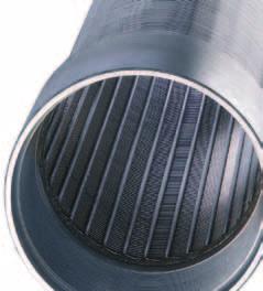
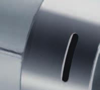
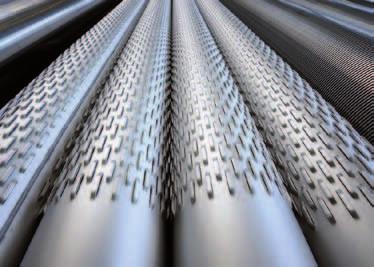
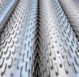
3 BRiDGE SloTTED SCREEnS/CASinGS bridge slotted screens and CasinGs STÜWA bridge slotted screens and casings are at the cutting edge when it comes to stability and material quality. They offer many advantages: Advantages series production up to 6 m without circular seam. longitudinal seam welded inside and outside High mechanical stability due to special arrangement of the slots slot widths of 0.5 mm or more feasible (depending on wall thickness) large wall thicknesses up to 12 mm feasible High installation reliability and safety efficient and cost-effective installation special lengths feasible large open areas excellent regeneration capability Screens and casings with various connections Screen with Rilsan coating Gravel pack screens K03-SBF

4 BRIDGE SLOTTED SCREENS/CASINGS Materials Basic material Stainless steel, different qualities depending on ground water properties and temperature. Steel - mild steel, preferably S235JR or similar steel with good weldability properties. Suitable for drawdown wells. Not approved for drinking water. Steel - galvanized, S235JR as base material. Only suitable to a limited extent for contact with drinking water. Steel - coated plastic, S235JR as base material, Rilsancoated, approved for drinking water. Meets the KTW recommendation of the German Federal Department of Health. Properties and suitability of stainless steel M No (X5CrNi18-10), AISI 304 This type of steel is resistant to water and slightly polluted waste water as well as weak organic and inorganic acids. Generally it is resistant to a ph value up to approx. 4.5 in aggressive substances low in chloride. M No (X2CrNi19-11), AISI 304L Similar properties as but with lower carbon content, resulting in an increased resistance to intergranular corrosion, which can occur, e.g. during the welding process. M No (X2CrNi18-9), AISI 304L Similar properties as but with slightly lower Ni content. M No (X6CrNiTi18-10), AISI 321 Stainless steel has excellent resistance properties to a variety of aggressive media. Furthermore, this material is characterised by a good ductility. M No (X2CrNiMo ), AISI 316L Better general resistance compared to , , and 1.451, particularly in case of increased chloride content. Resistance to intergranular corrosion is ensured by limiting the carbon content. M No (X6CrNiMoTi ), AISI 316Ti Similar properties as but with guaranteed resistance to intergranular corrosion due to titanium content. M No (X2CrNiMoN22-5-3) Duplex This duplex steel is characterised primarily by its high pitting and stress corrosion resistance in neutral and chlorinecontaining media resulting in good resistance to seawater. M No (X1CrNiMoCuN ) High resistance to phosphorus and sulphuric acid media with simultaneous chloride contamination. Additional material grades available on request K03-SBF


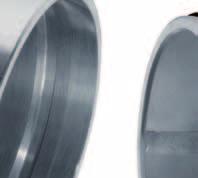
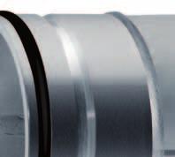
5 BRiDGE SloTTED SCREEnS/CASinGS COnneCtiOns 1 2 Selecting the best connection The choice of connections largely depends on technical requirements such as tensile strength, collapse resistance, and installation guidelines for construction sites. in addition, the outer diameter of the respective connection should be considered also, which is larger than the pipe diameter. Overview of connection types ZSM connection with restraining rod 2 Round thread connection 3 Flange connection 4 Screwing bar connection 5 APi thread connection 6 Restraining bar connection 7 Welding bridge connection K03-SBF
6 BRiDGE SloTTED SCREEnS/CASinGS COnneCtiOns 2 2 Connections external diameter d3 Nominal diameter DN ,000 Welding bridge [mm] ,044 Screwing bar incl. bolt head, company standard [mm] ,059 Restraining bar, company standard [mm] Round thread [mm] ZSM [mm] API thread [mm] DIN flange [mm] ,120 Connections inner diameter d2 Welding bridge [mm] Screwing bar, company standard [mm] Restraining bar joint, company standard [mm] ISO round thread [mm] ZSM [mm] API thread [mm] DIN flange [mm] ZSM DIN d2 Round thread DIN and ISO/API d2 Screwing bar DIN d 3 d 2 Welding bridge DIN d 3 d 2 Shear bar Sealing ring Sealing ring S1 S1 d3 d3 S 1 S 1 API thread Flanges DIN Hex nut M16 DIN S1 Disc 17 DIN nr St Sealing gasket d3 Hex screw M16 S 1 d 3 d K03-SBF
7 CASINGS TECHNICAL DATA 1 4 Pipe diameters compliant to ISO/API Nominal diameter DN ,000 Test mandrel Ø [mm] Outer Ø [mm] / / /804 1,016/964 Wall thickness [mm] Collapse resistance of casings made from steel/stainless steel Nominal diameter Wall thickness [inch] [mm] [mm] Collapse resistance [PSI/bar] 3 ½ , , , , ½ , , , , , , ½ , , , / , , , , , , , , , , / , , , / , , , , / , , , , ¾ , , , ¾ , , ¾ , , , , / , , , , / Larger dimensions available on request. Table from Butting catalogue issue 222/1999 p. 50 Calculation based on API Bul 5C3 Strength value: 275 N/mm2 (4000 PSI) comparable with API material H40 Collapse resistance in bar (min.) K03-SBF
8 t k a3 a2 a1 h STÜWA Konrad Stükerjürgen GmbH BRiDGE SloTTED SCREEnS technical data 2 4 Pipe diameters compliant to ISO/API Nominal diameter DN ,000 Test mandrel Ø [mm] Outer Ø [mm] / / /804 1,016/964 Wall thickness [mm] Free opening for screens with high performance bridge slotting screen perforations S1 h Wall thickness s1 Bridge opening h Free opening fi [mm] [mm] [%] Additional wall thicknesses available on request lengths of up to 6 m are manufactured without circumferential seam. w w b b a1 a2 t S1 Up to 35% open areas The bridge slot openings may have a tolerance of +/- 0.2 mm, which means that the values listed above for the open area are approximate values. Approx. 2 mm minimum opening for galvanized and Rilsancoated screens since the bridge openings could otherwise become plugged due to the coating process. Gravel pack screens Gravel pack screens allow an installation without a gravel base. The advantages of this screen type are: slim diameter, uniform grain size, high porosity. Nominal diameter Outer Ø above gravel sheath d DN [inch] [mm] Gravel Kiesbelag pack d K03-SBF
9 BRIDGE SLOTTED SCREENS TECHNICAL DATA 3 4 Free opening for standard bridge slotted screen DIN 4922, Part 1 Tool dimension a1 Wall thickness s1 Bridge opening h Medium slot length a2 Slot width w Longitudinal division t Side bridge b Free opening approx. fi [mm] [mm] [mm] [mm] [mm] [mm] [mm] [%] Tool dimension a1 Wall thickness s1 Bridge opening h Medium slot length a2 Slot width w Longitudinal division t Side bridge b Free opening approx. fi [mm] [mm] [mm] [mm] [mm] [mm] [mm] [%] The slot width tolerance compliant to DIN is +/- 0.2 mm, which means the values listed above for the open area are approximate values. Approx. 2 mm minimum opening for galvanized and Rilsan-coated screens, since the bridge openings could otherwise plug due to the coating process K03-SBF
10 BRiDGE SloTTED SCREEnS technical data 4 4 Free opening for standard bridge slotted screen DIN 4922, Part 1 Tool dimension a1 Wall thickness s1 Bridge opening h Medium slot length a2 Slot width w Longitudinal division t Side bridge b Free opening approx. fi [mm] [mm] [mm] [mm] [mm] [mm] [mm] [%] lengths of up to 6 m are made without circumferential seam The slot width tolerance compliant to Din is +/- 0.2 mm, which means the values listed above for the open area are approximate values. h S1 Approx. 2 mm minimum opening for galvanized and Rilsan-coated screens, since the bridge openings could otherwise plug due to the coating process. w b a1 a2 t K03-SBF


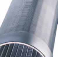
11 WiRE WRAPPED SCREEnS Wire Wrapped screens Wire wrapped screens were already developed and in use in the U.S. about 90 years ago. This design makes it possible to adjust the slot width with minimum tolerances to the characteristic grain-size distribution curve of the respective aquifer and manufacture the slots in such a way that an optimal sand removal from the adjoining natural rock is possible. Advantages in-house manufacturing short delivery times manufacturing in compliant to din 4935 The wire wrapped screen provides optimal conditions for the well development (pistoning, pumping, jetting). The kinetic energy of the flowing water is increased by the nozzle of the conical slots. The wire wrapped screen, with its inward expanding slots, is particularly suitable for the inflow of water laden with small particles. Thus clogging is avoided K03-WDF
, AISI 304L Similar properties as 1.")
12 WIRE WRAPPED SCREENS Materials 1 1 Basic material Stainless steel of different qualities to suit the ground water properties and temperature Properties and suitability M No (X5CrNi18-10), AISI 304 This type of steel is resistant to water and slightly polluted waste water as well as weak organic and inorganic acids. Generally, it is resistant to a ph value up to approx. 4.5 in aggressive substances low in chloride. M No (X2CrNi19-11), AISI 304L Similar properties as but with lower carbon content, resulting in an increased resistance to intergranular corrosion, which can occur e.g. during the welding process. M No (X2CrNi18-9), AISI 304L Similar properties as but with slightly lower Ni content. M No (X6CrNiTi18-10), AISI 321 This stainless steel has excellent resistance properties to a variety of aggressive media. Furthermore, this material is characterised by a good ductility. M No (X2CrNiMo ), AISI 316L Better general resistance compared to , , , , particularly in case of increased chloride content. Resistance to intergranular corrosion is ensured by limiting the carbon content. M No (X6CrNiMoTi ), AISI 316Ti Similar properties as but with guaranteed resistance to intergranular corrosion due to titanium content.. M No (X2CrNiMoN22-5-3), UNS (Duplex) This duplex steel is characterised primarily by its high pitting and stress corrosion resistance in neutral and chlorinecontaining media resulting in good resistance to seawater. Additional material grades available on request K03-WDF

 5 Connection outer")
![diameter d3 compliant to DIN 4935 Nominal diameter DN 100 125 150 200 250 300 350 400 500 600 800 1,000 Round thread [mm] 138 164 190 245 295 345 380 435 550 ZSM [mm] 140 170 190 251 304 352 401 443](/docs-images/90/103921055/images/13-3.jpg "543 643 - Shrink-on PVC trapezoidal thread connection [mm] 125 152 180 247 304 359 433 490 DIN flange [mm] 606 706 920 1,120 Connection outer diameter d3 compliant to API standard Nominal diameter")
13 WiRE WRAPPED SCREEnS COnneCtiOns 1 2 Selecting the best connection Connection types overview The choice of connections largely depends on technical requirements, such as tensile strength, compressive strength, and installation guidelines for construction sites. Please allow us to find just the right solution for your requirements. The outer diameter of the respective connection should be considered also, which is larger than the pipe diameter. All connections can be supplied separately ZSM connection 2 Round thread connection 3 APi thread connection 4 Flange connection 5 Shrink-on PvC trapezoidal thread connection (also available in stainless steel) 5 Connection outer diameter d3 compliant to DIN 4935 Nominal diameter DN ,000 Round thread [mm] ZSM [mm] Shrink-on PVC trapezoidal thread connection [mm] DIN flange [mm] ,120 Connection outer diameter d3 compliant to API standard Nominal diameter DN API thread [mm] K03-WDF
14 S 1 d 3 STÜWA Konrad Stükerjürgen GmbH WiRE WRAPPED SCREEnS COnneCtiOns 2 2 ZSM DIN Round thread DIN PVC thread joint* API thread ø d3 S1 Shear bar Sealing ring Sealing ring S1 ø d6 S1 ø d3 * alternatively trapezoidal thread in stainless steel 1. Round thread - DIN 4922 This type of thread was developed in Germany. it has some distinct advantages over other thread types (pointed and fine thread): Good load rating Good screw-in property, even with stainless steel Surface coating with epoxy or polyamide; even galvanizing is possible - fine threads would clog in this case 2. Round thread - company standard Favourable joining type 3. API (AMERICAN PETROLEUM INSTITUTE) THREAD These threads are needed during the construction of a well, whenever oil field pipes in the customary inch dimensions are used on international construction sites and the corresponding threads must be attached to the screen pipes. normally, the so-called casing thread is used for pipes compliant to specification 5A, table The specification for this thread is STD 5B. The following types apply: Table CASING SHORT THREAD (short thread, the most commonly used type of thread). Table CASING LONG THREAD (long thread) Some dimensions are not included in specification 5A. This is especially applicable for size Dn 300, according to APi 5l size 12 3/4" with an outer diameter of mm. When manufacturing threads for screens, care has to be taken that all threads are produced in compliant to table 2.1 "line PiPE." in some countries, thread type "BUTTRESS" is mandatory. 4. ZSM push fit/spring lock connection (DIN ) This joint type is used quite often. The advantage is in the easy and quick assembly on site. Depending on the load case, the restraining rod absorbing the tensile forces can be in the form of a rod (material grade polyamide) or a spring (material grade stainless steel ). A corresponding cable can also be used if the tensile forces are very high. 5. PVC thread connection A combination with PvC material is possible. This variation allows for a more economical solid pipe installation. The lower weight is another advantage. 6. Flange connection (DIN ) Flange connections are used in particular for connecting pipes with larger diameters K03-WDF
15 WiRE WRAPPED SCREEnS CASinGS technical data 1 4 Screen dimensions as to company standard Nominal diameter Test mandrel Ø Support rods Ø Inner Ø Outer Ø Collapse resistance* Weight DN [inch] [mm] [mm] [mm] [mm] [bar] [kg/m] ½ ½ ⁵ ₈ ⁵ ₈ ⁵ ₈ ⁵ ₈ ¾ ¾ , , Threaded connections Outer ø Inner ø rods (*) information about the collapse resistance includes consideration of a safety margin. larger dimensions available on request K03-WDF
16 WIRE WRAPPED SCREENS TECHNICAL DATA 2 4 Strengths of wrapped wire screens The decisive factor for dimensioning and application range of wrapped wire screens are the forces, to which the screen is exposed during installation and when installed. Considerations include collapse resistance and tensile strength. 1. Collapse resistance The wire determines the collapse resistance based on head width and in particular profile height (in our lists W = width and H = height). The rods are not considered in the calculation of the collapse resistance. The different manufacturers usually use an equation for their calculations, which is verified by pressure tests conducted in practice. Determining the required / desired collapse resistance is done in our company according to the following frequently used international equation: per meter installation depth 1 PSI (pounds per square inch) of external pressure. Example: Installation depth 100 metre ^= collapse resistance 100 PSI 100 PSI correspond to 7.0 bar. 2. Tensile strength The tensile strength is determined by quantity and diameter of the rods. It ultimately determines the value of the tensile strength of the entire screen train. The tensile forces are absorbed by the rods in a vertical direction. Thus, the screen body can be exposed to significant loads in the vertical direction. Example (assumed tensile strength: 500 N/mm 2) : Screen DN 200 with 40 rods Ø 4 mm Total cross-section of the rods = 40 x r2 x π 40 x 2 x 2 x π = 503 mm2 x 500 N/mm 2 = Kn Therefore the permissible tensile load is: tons. 3. Pressure load A wire wrapped screen may never be subjected to pressure. Consequently, the screen must always be suspended in the well. The collapse resistance must be at least 0.07 bar per meter of installation depth. The assumption is that the liquid column in the annular space and inside the pipe extends to ground level (upper edge of ground). In some special cases, a value of 1.5 PSI is assumed, namely when problems with the drilled are suspected (fractures, drilling sludge or fluid mud due to mud or circulation losses, gravel collapsing into hole). The calculation model at hand is not a verifiable static proof but a determination of reference values or benchmarks that are commonly used to determine the dimensioning of well construction pipes K03-WDF
17 WIRE WRAPPED SCREENS TECHNICAL DATA 3 4 B: Profiles of the well screen series and open areas in % Profile B/H [mm] Slot widths (SW) [mm] 2.5 x x x x x x x Profile W/H = X = calculation of the open SW x 100 % Rods areas using to the equation: SW + W 3.65 mm 3.9 mm 6.35 mm K03-WDF
18 WIRE WRAPPED SCREENS TECHNICAL DATA 4 4 Filter capacity (l/s) per metre screen (v = 30 mm/s) Nominal diameter Outer Ø Profile Slot width DN [inch] approx. [mm] [mm] , Larger dimensions on request K03-WDF
19 ACCESSoRiES CenterinG devices Centering devices for stainless steel installations in order to install screens and casings centred into the well, the use of centering devices or guides is recommended. The guides are attached at intervals of 6 to 10 m. Centering devices and guides are offered in the following materials: M No (X5CrNi18-10), AISI 304 This type of steel is resistant to water and slightly polluted waste water as well as weak organic and inorganic acids. Generally, it is resistant to a ph value up to approx. 4.5 in aggressive substances low in chloride. M No (X6CrNiMoTi ), AISI 316Ti Similar properties as but with guaranteed resistance to intergranular corrosion due to an excessive titanium content. 1 Additional material grades available on request Standard centering devices consist of a clamp and 4 deflectors. Cage centering devices consist of 2 clamps and 4 deflectors. Please Note: only use properly maintained tools for installation purposes Cage centering with screwed-on PvC skids for galvanic isolation* 2 Cage centering guides 3 Standard centering devices with 2 vertical sounding pipe clamps offset by 180 degrees* * Available against a surcharge K03-ZEW
20 installation ToolS installation tools Installation tools for screens and casings made from steel Lifting caps lifting caps for a safe and trouble-free removal and lowering of the pipe section. Steel lifting caps are especially suitable for use under extreme conditions and for long term use. 1 2 Support clamps Support clamps are suitable for the safe support of pipe sections. Strap wrench Strap lengths of 750 mm (up to Dn 200) and 1200 (from Dn 250 to Dn 300). 3 4 Please Note: only use properly maintained tools for installation purposes lifting flange 2 lifting cap round thread 3 lifting cap ZSM 4 Steel support plate 5 Steel support clamp 6 Wood support clamp 7 Strap wrench K03-ZEW