Towards cost-effective and low defectivity DSA flows for line/space patterning
|
|
|
- Ezra Horton
- 5 years ago
- Views:
Transcription

1 Towards cost-effective and low defectivity DSA flows for line/space patterning Hari Pathangi, Arindam Malik, B.T. Chan, Varun Vaid, Nadia Vandenbroeck, Roel Gronheid Jin Li, Baskaran Durairaj, JiHoon Kim, SungEun Hong, Yi Cao, Guanyang Lin


2 DSA line/space test vehicles at imec 14 nm half pitch LiNe flow 15 nm half pitch SMART TM flow All DSA materials (mats, brushes and BCPs) used in this work were synthesized by Merck 2


3 DSA: a cost perspective Modified imec wafer cost model v3.2 used in the analysis Compared SAQP vs DSA for front-end line patterning exercise Main conclusions were DSA adoption would reduce the number of process steps significantly The number of lithography steps in both the alternatives are same Hard-mask stack strategy for DSA process is simpler Tool time would be less First promising signs for DSA 3
 BCP anneal duration Current")
4 But, will BCP anneal duration ruin the advantage? BCP anneal duration: most critical process step from a cost perspective Current PoR single wafer anneal in litho track Low defectivity DSA typically needs long(er) BCP anneal duration Current defectivity PoR anneal = 255 O C for 2.5 hours (hotplate) Optimal BCP anneal from a cost perspective was demonstrated <5 min single wafer anneal has clear cost benefit for DSA vs SAQP 4

5 But, will BCP anneal duration ruin the advantage? What if <5 min BCP anneal is not an option for low defectivity? Possible solution Migrate to a batch anneal process Can anneal 150 wfs together Using a batch anneal process increases the anneal time budget to 60 minutes AND maintains cost advantage 20% -20% -17% What are these defects and where do they come from? 5


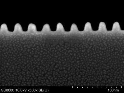
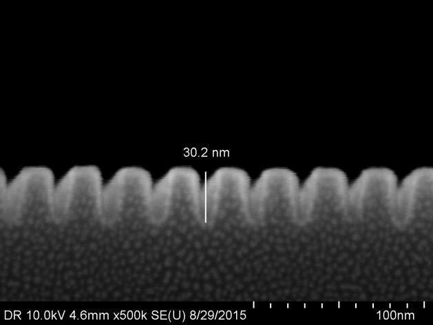
6 What do the defects look like? 6 Optical broadband plasma defect inspection and SEM review

7 Where do these defects come from? Possible source of defects 1. DSA and/or non-dsa material impurities induced particles, chemical composition of brush/bcp, PDI, photoresist strip chemistry, mat surface energy modification,.. 2. Non-ideal chemical pattern guide CD variation, non-ideal guide profile, mat/brush coating defects, incorrect BCP thickness,.. 3. Non-ideal BCP anneal conditions incorrect anneal technique, time, temperature, quenching kinetics,.. 4. Equipment induced from tracks, non-ideal PoU filtration, scanners, etch chambers.. 5. Interaction of two or more of the above factors 7


8 Golden defect performance at imec: 14 nm hp LiNe flow


 Claim topography in SMART flow chemical pattern led to low")
9 Cost reduction is only useful if DSA is defects-free! Any cost reduction strategy has to go in parallel with defect reduction Are we missing any other approach for aggressive defect reduction? Inspiration: LiNe SMART defectivity work LiNe flow: Major defect mode = dislocations SMART flow: Major defect mode = bridges (dislocations not observed) Claim topography in SMART flow chemical pattern led to low tendency for dislocations 9
10 Can we take advantage of topography without SMART flow? We propose an imec-based approach for DSA L/S patterning Trench Assisted Chemoepitaxy = TRAC flow Addresses the main processing problems of the LiNe and SMART flows: i. LiNe: Plasma trim etch hardens the resist Complicates strip process ii. iii. iv. LiNe: No EHS-friendly strip chemistry LiNe: Post-trim XPS guide profiles are sloped exact chemical pattern difficult to define LiNe: No topography in chemical patterns v. SMART: uses NTD process to pattern trenches Challenging to scale vi. SMART: post strip-surface treatment Exact effect on process yet to be identified 10

11 TRAC flow Patent filed 11
12 TRAC flow: Process details 1. Mat coating and PTD litho process Similar to LiNe flow 2. PR lines trimmed using chemical line shrink materials a) No plasma involved no resist hardening 3. Top surface of mat (XPS) modified by exposure to soft O 2 plasma a) Exposure time to plasma ~ 2 seconds b) PR line CD loss after plasma exposure ~ nm 4. PR strip can be done with standard track solvents like RER600, RER650 etc. a) Good strip efficiency of RER600, RER 650 experimentally verified 5. Brush graft + BCP coat & anneal Similar to LiNe flow a) Chemical patterns have topography does this influence dislocation defects? b) Pinning layer inside a trench 6. On-going: to check the exact amount of topography in chemical patterns: AFM + TEM 12

 Considerable simplification of")


13 First TRAC flow results Good DSA performance observed from top-down SEM PR strip done with RER 600 (45 seconds strip duration) Considerable simplification of the strip process compared to LiNe and SMART flows But, how is this more cost effective? Possibility of mat modification in the litho track? This will enable an all-track DSA process flow! 13
 show promising DSA (with defects) Surface modification")

14 In-track mat surface modification Initial tests (using non-optimized conditions) show promising DSA (with defects) Surface modification module On-going Optimization of surface treatment conditions for selective mat modification Verification of defect-free assembly after mat modification 14


15 TRAC flow successful pattern transfer Post-PMMA removal Post-Si etch 15
 11, 950 defects cm -2 91% defects = Dislocations 7% defects =")

16 TRAC flow: first defect results New pattern transfer process was used to etch DSA lines into Si substrate Need to optimize etch process for defect improvements Initial defect levels of TRAC flow (after Si etch) 11, 950 defects cm -2 91% defects = Dislocations 7% defects = Residues Line trimming material = Manual dispense Further tests planned with track dispense Fine tuning DSA materials for TRAC flow is important! No 1-period bridge defects were found! Data collected across 3000 defect locations (from smart sampling) reviewed from 3 wafers 16
17 Wrapping-up.. 1. Cost calculations (and some common sense) indicate economic benefit for DSA 2. BCP anneal duration: important parameter might determine the final cost advantage 3. Defectivity control and cost reduction should go hand in hand 4. New imec-based approach for L/S DSA patterning (TRAC flow) Addresses the processing issues of LiNe and SMART flows A possible route towards all track DSA flow = further cost reduction for DSA A good test vehicle to understand the effect of topography on defects 17

18 Acknowledgements Takehito Seo Line trimming material for TRAC flow Kaushik Sah Andrew Cross Defect metrology Lucia D Urzo Hareen Bayana PoU Filtration Ainhoa Romo Paul Greenfield In-track mat modification DSA team members at imec 18

19