Modeling of Galvanic Interactions Between AA5083 and Steel Under Atmospheric Condition
|
|
|
- Scarlett Blake
- 5 years ago
- Views:
Transcription
1 Presented at the 2011 COMSOL Conference in Boston Boston, MA, Oct Modeling of Galvanic Interactions Between AA5083 and Steel Under Atmospheric Condition D. Mizuno a),b), Y. Shi a), and R. Kelly a) a) University of Virginia b) JFE Steel Corporation 1 Acknowledgements :This work is funded by the Office of Naval Research N


2 Background LCS X-craft AA5083 alloys are widely used across the Department of Defense AA5083 is susceptible to IGC and IGSCC due to the sensitization during service Aluminum alloys are often joined via steel bolts There is a concern that galvanic interactions will exacerbate corrosion of the AA5083 leading to IGC and IGSCC. 2


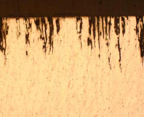
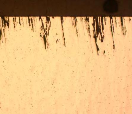
3 IGC damage of AA5083 Potentiostatic test Galvanic corrosion (steel :5083=100:1) Galvanic 300mm Galvanic (steel :5083=100:1) Avg potential = V PS:-0.80V 300mm PS:-0.80V 3 PS:-0.75V 300mm Solution : 0.6MNaCl Test duration : 100hours PS:-0.75V 200mm
4 The need for Modeling Galvanic corrosion under atmospheric condition is complicated due to the range of factors affecting the corrosion. Example : salt loading density, relative humidity, area ratio, temperature, geometry... It is necessary to investigate the influence of each environmental factor systematically to understand galvanic atmospheric corrosion. It is impossible to investigate so many conditions experimentally in the laboratory. 4
5 Objective To build the preliminary model to predict the potential and the current density distribution due to the galvanic coupling between AA5083 aluminum alloy and AISI4340 steel under a thin electrolyte to simulate atmospheric corrosion. 5
6 Model geometry Steel bolt AA5083 Thin electrolyte AA5083 Steel 5 4 domain 3 1.anode 2.cathode 6
7 Parameters in domain electrolyte Nernst-Plank equation: c i t = ( D i c i z i F D i RT ) = R i (1) Z i C i = 0 Parameters for chemical species Initial Concentration (mol m -3 ) Diffusion Coefficient (m 2 s -1 ) Na x 10-9 Cl x 10-9 H x 10-9 OH x 10-9 Al
8 Determination of Boundary Conditions 0.6 M NaCl 8
9 i Al0 exp(-a Ala (E Al0 -(V m -V))/R/T) Boundary conditions Equation consists of Butler-Volmer equation and cathodic diffusion plateau Boundary-1 : Anodic reaction (on AA5083) + i AlLim i Al0 exp(a Alc F (E Al0 -(V m -V))/R/T)/(i AlLim + i Al0 exp(a Alc F (E Al0 -(V m -V))/R/T)) Boundary-2 : Cathodic reaction (on steel) i FeLim i Fe0 exp((a Fec F (E Fe0 -(V m -V))/R/T)/ (i FeLim + i Fe0 exp(a Fec F (E Fe0 -(V m -V))/R/T)) Boundary type Parameters 1 2 anode cathode i Al0 (A/m 2 ) E Al0 (V SCE ) i AlLim (A/m 2 ) a Ala a Alc 9.6x x i Fe0 (A/m 2 ) E Fe0 (V SCE ) i FeLim (A/m 2 ) a Fea -5.6x x
10 Other conditions The limiting current density by oxygen diffusion i FeLim = zfd O2 C o2 / d d:thickness of diffusion layer The flux due to the electrochemical reaction Boundary Type Reaction flux of spieces 1 anodic reaction Al Al e - j Al3+ = i a / 3F 2 cathodic reaction O 2 + 2H 2 O + 4 e - 4OH- j OH- = i c / F 3-5 electric insulator The chemical reaction in domain: H 2 O = 2H + + OH - R H+ = R OH- = k wf - k wb [H + ] - [OH - ] where k wf =10-4 and k wb =


11 Experimental for model validation Scanning Kelvin Probe (SKP) Steel AA5083 AA5083-H131 and steel were combined together in epoxy resin (low sensitized 5083 was used) 0.6M NaCl was used to form the thin electrolyte layer Thickness of electrolyte : 1.0 and 0.1 mm RH was set at 98% to keep the condition of electrolyte. 11

12 Potential distribution under 1.0mm film Potential calculated by model had a good agreement with experimental data. 12

13 Current density distribution under 1.0mm film 13 Anodic current density on the 5083 increased with increasing the area ratio of steel. Anodic current density was almost constant in each area ratio condition.

14 Potential distribution under thin film The tendency of potential was similar between model calculation and experimental data. 14

15 Current density distribution under thin film Galvanic interaction under atmospheric condition will exacerbate the corrosion of AA5083 near its boundary with steel. 15
16 Summary 1. The preliminary model for predicting galvanic corrosion under atmospheric condition was developed. 2. Potential distribution in bulk solution calculated from this model had a good agreement with experimental data. 3. Potential distribution under thin electrolyte calculated from this model had similar tendency to the experimental data. 4. The model calculation indicates that galvanic interaction would exacerbate the corrosion of 5083 under atmospheric condition, with thinner electrolytes focusing the attack near the boundary with the steel. 16
17 Future work 1. To improve the model so that we can calculate under thinner electrolyte (less than 0.1mm). 2. To compare the IGC damage distribution predicted from the model with experimental data. 17

18 18 Thank you for your attention
19 19 Appendix


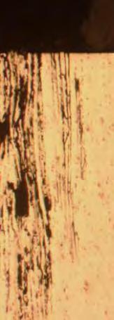
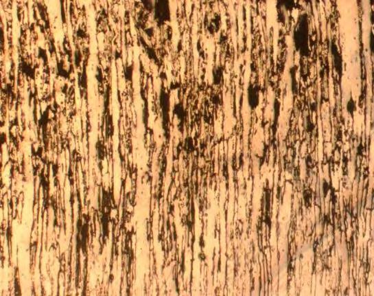
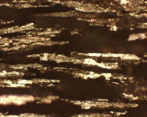
20 Corroded surface observation Area ratio DoS 2mg/cm 2 DoS 18mg/cm 2 DoS 50mg/cm 2 1:1 S T 1:15 1: mm


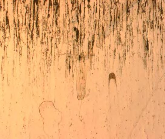
21 IGC damage by galvanic interaction Area ratio DoS 2mg/cm 2 DoS 18mg/cm 2 DoS 50mg/cm 2 L 1:1 S 1:15 1: mm
22 Influence of area ratio on IGC NMLT:50mg/cm 2 NMLT:18mg/cm 2 NMLT:2mg/cm 2 IGC depth tends to be deeper with increasing area ratio of steel. Dependence of area ratio on IGC increased with increasing DoS. IGC attack seems to have the power law relationship with area ratio. 22

23 The relationship between IGC damage and potential Solution : 0.6MNaCl Test duration : 100hours 23
24 Potential distribution under thin electrolyte Under 0.1mm thick 0.6MNaCl AA5083(DOS:50mg/cm 2 ) steel 24 Potential on 5083 near its boundary with steel was polarized to positive value which can cause IGC.
25 Why 0.6M-NaCl? Considering the situation that AA5083 alloys were used on the cabin of ships, they can get splash of sea water. 0.6M NaCl splash Concentration of NaCl increases with decreased thickness of electrolyte due to dry up Calculation from data of *1) The equivalent concentration changes depending on RH *1):J. C. W Frazier et al, International Critical Tables of Numerical Data, Physics, Chemistry and Technology Vol. III, W. W. Washburn, Editor, p292, McGraw-Hill, New York (1928). 25 It is difficult to add the influence of the thin electrolyte and the change of concentration due to the evaporation of water at the same time.
26 Why 0.6M-NaCl? Current study Future study Electrochemical behavior in 0.6MNaCl Electrochemical behavior in conc NaCl Acquisition of electrochemical parameter for modeling Comparison between bulk solution and thin electrolyte Corrosion behavior under thin electrolyte in 0.6MNaCl Comparison between conc bulk solution and thin electrolyte Validation of the model Modeling under thin electrolyte of 0.6MNaCl Advanced Modeling in which change of concentration is considered. 26 We focused on developing the model which we can apply under thin electrolyte first. In order to validate it, 0.6M NaCl should be used.
27 Problem of current model The thickness of electrolyte is thick, calculation will converge. However, the thickness of electrolyte is less than 0.1mm, calculation will NOT converge. Thin electrolyte AA5083 Steel Thin electrolyte AA5083 Steel The problem is How to make the mesh? Aspect ratio? Boundary condition? 27