FEM of cracking during nanoindentation and scratch testing in the coated systems František Lofaj
|
|
|
- Ezra Reeves
- 5 years ago
- Views:
Transcription


1 FEM of cracking during nanoindentation and scratch testing in the coated systems František Lofaj Institute of Materials Research of the Slovak Academy of Sciences Košice, Slovakia
2 Outline Introduction to IMR SAS/Divison of Ceramic & Non-metallic Materials Scientific lecture modeling of cracking during nanoindentation and scratch testing Tribological test vs. scratch test Nanoindentation Scratch testing

3 Institute of Materials Research of SAS ( since 1955)
 Department of structural ceramics (1990-2015) 12 persons + 5")
4 Division of ceramic and non-metallic systems ( ) Department of structural ceramics ( ) 12 persons + 5 PhD. students
5 Publications and projects in VD02 in 2017 Main activities/fields of interest: Microstructure and mechanical properties of bulk monolithic structural ceramics (silicon nitride, alumina, silicon carbide...) and (nano)composite ceramics Reinforced ceramics for special applications (graphene platelets/cnt reinforced ceramics) Properties of ultrahigh temperature ceramics (ZrB 2 based composites) SPS of ceramics PVD of hard coatings Fibers by electrospinning nanoindentation and tribological behavior of different materials Typ publikácie ADCA-Zahr.karent.čas.impaktovaný DAIb-Kvl.práce-doktorand.v angl. Písomná časť PhD.slov. AEDA-Ved.pr.v dom.recen.ved.zbor.konf. ADEA-Zahr.nekarent.čas.impaktované ADEB-Zahr.nekarent.čas.neimpaktované ADFA-Dom.nekarent.čas.impaktované ADFB-Dom.nekarent.čas.neimpaktované Počet publikácie Počet publikácie APVV 6 VEGA 4 SF projects 0 M-ERA 3 COST 3 Bilateral 1 Total 17

6 SEM/FIB ESEM Tribo/nanoindent TUKE ÚGt Igt SAS ÚPJŠ IEP SAS IMR SAS LM Chem. & Surf. Analyses Coat. Technol. SPS Advanced alloys Nanospider Powder preparation Powder characterization Laser treatment Thermal analyses mech. testing...


7 ... moderné materiály pre budúcnosť. Technologies PVD coatings (DC/HiPIMS and HiTUS) Spark Plasma Sintering Nanofibers (electrospinning) Laser treatment Amorphous metals Microwave sintering


8 High resolution microscopy W filament esem/eds, WDS FIB/SEM DualBeam FESEM TEM JEM-2100 F AFM Dimension Icon


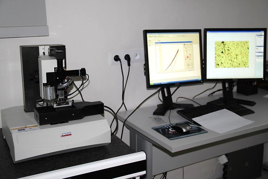

9 Nanohardness testing Nanohardness testers G200 (Agilent) NHT CSM Instruments


10 Tribology Raman GDOES
11 FEM of cracking during nanoindentation and scratch testing in the coated systems František Lofaj, Dušan Németh* Institute of Materials Research of the Slovak Academy of Sciences Košice, Slovakia * (currently at: Robert Bosch, Ltd., České Budějovice, Czech Republic)
 Kuiry, Bruker 2012 Differences: ball")
12 Introduction Tribological test vs. scratch testing (constant load/progressive load increase) Kuiry, Bruker 2012 Differences: ball diameters, higher maximum loads stronger deformation of the substrate..

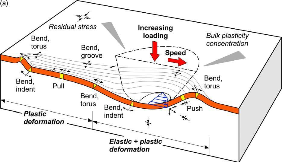
13 Basic processes during scratch test Holmberg Trib. Int Burnett Rickerby TSF 1988


14 Effects of interface sliding and friction during scratch test Tensile and compressive stresses L c1 L c2 Holmberg SCT 2006 L c3


15 Cohesive cracks (in the coating) analogous to frame cracks formed due to local tensile stresses Adhesive cracks in the coating Adhesive cracks at the coating/substrate interface
16 Modelling of the scratch tests Modelling in 2D; the first 3D models in 2003 (Holmberg) modelling of cohesive coatings - xfem (+ FEM) Bull Trib. Int Modelling of adhesive cracks modelling of plastic deformation - FEM Nanoindentation = progressive load increase scratch test with zero velocity
17 Objectives Finite element modeling of the processes of: cohesive cracking in hard brittle W-C coating/steel substrate during nanoindentation and scratch testing attempt to get information about the strength and toughness of coatings. Applicability: cracking in the transfer layer during tribological tests
; polished to R a ~10 nm Deposition procedure HiPIMS, 3 inch WC")

18 Experimental procedure Substrate: construction steel (12050) after hardening (860 o C/30 min, quenching into oil, tempering 200 o C/120 min); polished to R a ~10 nm Deposition procedure HiPIMS, 3 inch WC target, working pressure 0,5 Pa, 500W, a = 3% (200 Hz, 150 us), 2 vol.% of C 2 H 2 in Ar atmosphere, 34 min W-C coating, t = 991 ± 35 nm. thickness ~1000 nm Cryofox Discovery 500, Polyteknik, Danmark amorphous structure.


19 Experimental techniques Nanoindentation Scratch tester G200, Agilent Technologies Model UMT 2, Bruker, USA Berkovich indenter tip with R = 1.15 um CSM mode, f = 45 Hz, amplitude 2 nm constant depth of 1500 nm; constant strain rate 0.05 s -1, 4 x 4 = 16 indents. Rockwell C diamond tip R = 200 um; cone angle 120 o pre-load 2 N; linearly increased up to 100 N scratch length 7 mm indenter velocity mm/s


20 Results Multiple circular frame cracks in hard W-C coating/steel substrate during indentation 200 mn 300 mn 500 mn
21 Cracking during indentation indent A indent B indent C FEM without crack pop-in at 1285 nm load when strength of coating was reached.. Load [mn] Displacement [nm]

22 Evolution of principal tensile stresses and plastic deformation during nanoindentation Strength of the coating.. cohesive cracking controlled by substrate deformation

23 Principal stress distribution in coating/substrate at 200 mn load


24 xfem multiple crack evolution infinite bonding between the coating and substrate
25 Fracture toughness of W-C coating on steel from XFEM 240 Traction separation law Load [mn] indent A indent B indent C FEM- C1 = 0,001 m FEM- C2 = 0,008 m FEM- C3 = 0,01 m W-C coating fracture toughness Displacement [nm] σ max [GPa] G c [Gpa.µm] K IC [MPa.m 1/2 ] L cz [µm] δ c1 = 0,001 µm 9,535 0, ,246 0, δ c2 = 0,008 µm 9,535 0, ,524 0, δ c3 = 0,01 µm 9,535 0, ,939 0,068279
26 Scratch testing

27 Cohesive cracking during scratch testing l c2 =330 m l c1 =325 m l =600 m l c2 =330 m L c1 = 4.64 N L c2 = 4.71 N l c1 =330 m

28 Scratch topography Strong deformation zones along the scratch
29 Scratch test - Experiment vs. FEM

30 Vertical displacement along the scratch path

31 The distribution of principal stresses along the scratch path at L c1 High compressive stresses spalling/buckling (CZM??) Tensile stress reached coating strength Cohesive crack forms L c1
32 Scratch test - Experiment vs. FEM Experimental cracks FEM without cracking
33 Scratch test - Experiment vs. XFEM XFEM cracking The difference between XFEM and experiment.friction omitted; coating strength variation.
")
34 XFEM development of Chevron cracks in W-C coating during scratch test Chevron (angular) cracks
 Tensile (Burnett-Rickerby) Transverse semicircular")
35 XFEM evolution of Chevron cracks in W-C coating into arc-tensile cracks during scratch test Arc-tensile (ASTM) Tensile (Burnett-Rickerby) Transverse semicircular (Holmberg)


36 Scratch test - Experiment vs. FEM* Fracture toughness of the W-C coating G c fracture energy, strength and c identical to those from nanoindentation K 1c = 3.5 MPa.m 1/2 (* Coating strength intentionally reduced to 7 GPa)
37 Conclusions Current work on the W-C coating/steel system successfully modelled: Cohesive cracks originating from the top coating surface in the sink-in zone and coating/substrate interface, during nanoindentation. Chevron cracks evolved into arc-tensile cracks during scratch testing. The formation of these cracks is controlled by the plastic deformation of the substrate. Nanoindentation and/or scratch testing in combination with XFEM can be used for the determination of the fracture toughness of the brittle hard coatings on softer substrates. Early stages of wear in coated systems can be understand.


![Young's modulus E [GPa] Yield](/docs-images/91/105455932/images/38-2.jpg "stress Rp [GPa] Poisson's ratio")

38 FEM parameters (+ xfem) diamond indenter W-C coating mesh refinement close to the indent Material parameters substrate Young's modulus E [GPa] Yield stress Rp [GPa] Poisson's ratio ʋ Indentor ,07 W-C coating ,28 Steel substrate 210 1,1 0,30
![Extended FEM for adhesive cracks 8 6 Crack initialization Traction-separation law Traction, [MPa] 4 2 G c](/docs-images/91/105455932/images/39-2.jpg "= max.")
39 Extended FEM for adhesive cracks 8 6 Crack initialization Traction-separation law Traction, [MPa] 4 2 G c = max. Crack process zone onset of crack propagation Fracture energy Crack separation, [nm]

40