Module Design for MIEC Membranes. in OXYCOAL-AC
|
|
|
- Emil Copeland
- 5 years ago
- Views:
Transcription

1 CCT 2009 Module Design for MIEC Membranes in E.M. Pfaff*, M. Zwick, S. Dabbarh, C. Broeckmann Institute for Materials Applications in Mechanical Engineering 1

2 Module design in Agenda 1. Introduction 2. Materials 3. Joining Techniques 4. Membrane Concepts 5. Conclusion 2
3 Oxyfuel-Combustion Simple Oxyfuel-Process Air ADECOS-Concept CO 2 Steam AF Oxygen N 2 O 2 + CO 2 Coal Water Oxycoal-AC-Process AF = Air Fractorization Air CO 2 Steam BMWI-Project at Aachen University 6 Mechanical Engineering Institutes Industrial participants: EON, RWE, MAN-Turbo, Hitachi, Linde, WPS N 2 OTM O 2 + CO 2 Coal OTM = Oxygen Transport Membran Water 3
")
 Air 850 C, 20 bar Exhaust gas 850 C, 1 bar")
4 Pressure driven OTM-Reactors Air Air 20 bar CO 2 N 2 Air 20 bar O 2 OTM tube Inner metal tube N 2 (+ O 2 ) CO 2 (+ O 2 ) N 2 (+ O 2 ) Exhaust gas CO 2 O 2 O 2 ( bar) Air 850 C, 20 bar Exhaust gas 850 C, 1 bar 4
5 Extraction by vacuum pump Measured by S.Engels RWTH 2009 Air 20 bar O 2 N 2 (+ O 2 ) Ba 0.5 Sr 0.5 Co 0.8 Fe 0.2 O 3-x J O 2 (0.8 bar) O 1 2 = C( T ) ln Sm p p O air O 2 2 flue lower po 2 -ratio means: - lower permeation rate - larger membrane area Comparison of Oxygen Flux (850 C, 20 bar air) for 1mm Ba 0.5 Sr 0.5 Co 0.8 Fe 0.2 O 3-x p O2 -ratio Vacuum 800 mbar: 5 Exhaust gas: 25 1 ml/cm 2 min 2 ml/cm 2 min 5
 Oxygen Flux FORCE FLOW F (mechanical) MASS- FLOW D (chemical) CERAMIC COMPONENT spring/damping/ friction-element")
 insulating/ conductingelement CERAMIC / NONCERAMIC")
6 Fundamentals of OTM-Design Outer influences: High temperature (850 C) Air pressure up to 20bar (Feed) Corrosive atmosphere (Permeate) Vacuum (Permeate) Oxygen Flux FORCE FLOW F (mechanical) MASS- FLOW D (chemical) CERAMIC COMPONENT spring/damping/ friction-element (safety belt) surface cover Requirements: Gas tight joining (Feed Permeate) Long term stable joining High mechanical strength of materials High chemical resistance High creep stability HEAT FLOW Φ (thermal) insulating/ conductingelement CERAMIC / NONCERAMIC ENVIRONMENT 6
7 Mechanical strength of Ba 0.5 Sr 0.5 Co 0.8 Fe 0.2 O 3-x Probability of Failure (% ) 1,933 1,527 1,097 0,834 0,476 0,186-0, ,367-0,672-1,031-1,5-2,361-2,25-2,484-2,623-2,783-2,97-3,199-3,491-3,902-4,824-4,706-4,6-4,958-5,113-5,296-5,52-5,808 Weibull Probability of Failure own material development Sample: Ø = 15 mm, l = 10 mm Component: Ø = 15 mm, l = 500 mm Ø13 mm F σz Ø15 mm 10 mm Al 2 O Fracture Stress Characteristic strength σ 0 = 130 MPa (sample size) ~50 MPa (component size) Weibull modulus m = 6,7 Size effect Temperature effect σz (850 C) / σz (RT) 0.6 σ 1 σ 2 = V 1 2 V 1 m V 7
8 Materials Characterisation S [μm] k 1=0,95 μm/h F=47 N 850 C σ 950 C z =34 MPa 900 C S Ø1 Ø2 Creep Ø1 (vor Messung) : 11,08 mm Ø2 (vor Messung) : 10,76 mm k 2=8,1 μm/h k 3=52,8 μm/h Time [h] α tech [10e -6 /K] Coefficient of thermal expansion Temperature [ C] λ [W/mK] Head capacity and thermal conductivity 1,6 1,6 λ 1,2 1,2 0,8 0,8 0,4 C p 0,4 0,0 0, Temperature [ C] C p [J/gK] Material ρ ρ th σ O-Ring m σ 4PB E α λ [g/cm³] [g/cm³] [MPa] [-] [MPa] [GPa] [10-6 K -1 ] [W/mK] BSCF 5,70 5, , ,2 1,8 SCMF (porous) 3,84 5, , ,8 2,2 ln(ln(1/1-f)) ln(ln(1/1-f)) Failure propability p i F F=43,5% F=1% Δm [%] Corrosion in exhaust gas Exhaust gas BSCF Exhaust gas SCMF Microstructure -6 2,5 2,75 3 3,25 3,5 3,75 4 4,25 4,5 ln σ [MPa] ln σ [MPa] 4,75 5 5, Temperature [ C] 8
9 Materials Characterisation S [μm] k 1=0,95 μm/h F=47 N 850 C σ 950 C z =34 MPa 900 C S Ø1 Ø2 Creep Ø1 (vor Messung) : 11,08 mm Ø2 (vor Messung) : 10,76 mm k 2=8,1 μm/h k 3=52,8 μm/h Time [h] α tech [10e -6 /K] Coefficient of thermal expansion Temperature [ C] λ [W/mK] Head capacity and thermal conductivity 1,6 1,6 λ 1,2 1,2 0,8 0,8 0,4 C p 0,4 0,0 0, Temperature [ C] C p [J/gK] Material ρ ρ th σ O-Ring m σ 4PB E α λ [g/cm³] [g/cm³] [MPa] [-] [MPa] [GPa] [10-6 K -1 ] [W/mK] BSCF 5,70 5, , ,2 1,8 SCMF (porous) 3,84 5, , ,8 2,2 ln(ln(1/1-f)) ln(ln(1/1-f)) Failure propability p i F F=43,5% F=1% Δm [%] Corrosion in exhaust gas Exhaust gas BSCF Exhaust gas SCMF Microstructure -6 2,5 2,75 3 3,25 3,5 3,75 4 4,25 4,5 ln σ [MPa] ln σ [MPa] 4,75 5 5, Temperature [ C] 9
 - resoluble - temperature sensitive -")


10 Joining alternatives Metal Ceramic Joint Force Closure - gas tight (sealing elements) - resoluble - temperature sensitive - high joining stresses Solid Closure - gas tight - not resoluble - high temperature rang - adjustable joining stresses Form Closure - not gas tight - resoluble - temperature sensitive - low joining stresses Only at low temperature Possible joining for OTM-applications 10


11 Brazing Reactive Air Brazing (RAB) Ceramic/Metal-Joints Method: - Air atmosphere - Joining temperature <1000 C - Presureless RAB-braze BSCF Advantage: - No degredation of Perovskite by O 2 -removal - Excellent wettability - Similar CTE P5 - Low Joining stresses Steel Braze diffuses into porous substrates BSCF = Ba 0.5 Sr 0.5 Co 0.8 Fe 0.2 O 3-x No long term experience 11


12 Geometrical brazing optimization Brazed seam on inner side Brazed seam on outer side BSCF Outer side BSCF σ max Ag/CuO σ max St Ag/CuO St Outer side Burst testing: Inner side brazed seam < 10bar Outer side brazed seam >35bar reduction of joining stresses! 12


13 Alternatives for membrane elements Source: HITK Tubes Honeycombs Joining Problems for honeycoms Patent of Norsk Hydro Foils Solid Oxid Fuel Cell, Research-Center-Jülich 13
 400 mbar (Permeate site) 1m 2 -Test Module with 42 tubes 14")
14 Module design in One side closed tubes allow: - cold joining T < 200 C (O-Rings, Glue) - warm joining T < 600 C (Brazing) Low temperature at metal-components - metal alternatives - large module units possible - low heat lost Parameters: C 5-20 bar air (Feed site) 400 mbar (Permeate site) 1m 2 -Test Module with 42 tubes 14


15 Module design for larger applications Inner Isolation Membrane Tubes Degraded Air Air in Base Plate Geometrie Diameter : 600 mm Tubes per plate: 500 Total Tubes: 1000 Tubes Length: 500 mm Membrane Area: ~ 23,5 m 2 O 2 Air in Degraded Air Oxygen capability: 1.4 tons per day 15
 insulated Manifolds Base Plate Exhaust Oxygen lower Pressure Tank Oxygen capability: 2.")
16 Modulare Assembly Pipework concept allows duplicating for larger units Upper Pressure Tank Flange Security Devices Valves (switch off defect modules) insulated Manifolds Base Plate Exhaust Oxygen lower Pressure Tank Oxygen capability: 2.8 tons per day 16


17 Planar design, Air Products Oxygen capability per module 0.5 tons per day bar (14-20 bars) Oxygen capability 3 tons per day Presented at Gasification Technology 2005 and
18 Conclusions Glass (14-20 bar seals applicable up to 600 C bars) Best choice for 3-end: cooled joints using special glues Concept Principles 4-end concept with overflowing exhaust gas best efficiency but CO 2 -poblem for BSCF-ceramic 3-end concept with extraction O 2 by vacuum pump applicable for vaccum > 0.3 bar, needs compressed air on feed site Structures Tubes seems to be best choice: high packing density, easy to join, optimum diameter for 3-end: Ø = 10 mm Joining Handling of high thermal expansion RAB manageable, up to now no long term experience Modul design Modular concept necessary for removement of failed ceramic tubes 18
19 Thanks for Attention The authors gratefully acknowledge financial support by BMWi and MIWFT as well as the companies RWE Power AG, E.On AG, Hitachi Power Europe, Linde AG, MAN Turbo and WS-Wärmeprozesstechnik. 19
20 Back-Up 20
21 Size effect on fractural strength σ 1 σ 2 = V 1 2 V 1 m V F Depends on scattering strength values (m=10) Strength depends on surface finishing F F Ø30x1 20 4,5 3,5 10x1x10 40 (3-Punkt-Auflage) Ball on 3 balls V effx /V eff1 1 (15,62 mm³) 0, ,026 σ 87 MPa 193 MPa 125 MPa F Ø10x1 p i 10x1x10 p i 10x1x500 V effx /V eff1 >1 5,91 295,58 σ < 87 MPa 73 MPa 50 MPa 21


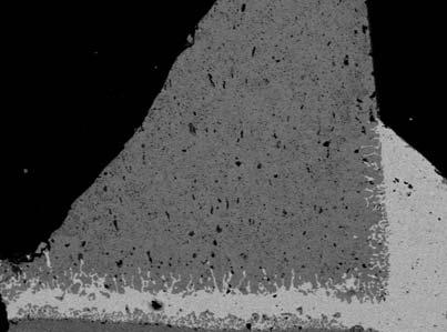

22 Influence of brazing parameters Infiltration of braze into BSCF 22