Strength of inserts in titanium alloy machining
|
|
|
- Nickolas Wesley Lee
- 5 years ago
- Views:
Transcription
1 Strength of inserts in titanium alloy machining V Kozlov, Z Huang and J Zhang Tomsk Polytechnic University, 30, Lenina ave., Tomsk, , Russia kozlov-viktor@bk.ru Abstract: In this paper, a stressed state of a non-worn cutting wedge in a machined titanium alloy (Ti6Al2Mo2Cr) is analyzed. The distribution of contact loads on the face of a cutting tool was obtained experimentally with the use of a split cutting tool. Calculation of internal stresses in the indexable insert made from cemented carbide (WC8Co) was carried out with the help of ANSYS 14.0 software. Investigations showed that a small thickness of the cutting insert leads to extremely high compressive stresses near the cutting edge, stresses that exceed the ultimate compressive strength of cemented carbide. The face and the base of the insert experience high tensile stresses, which approach the ultimate tensile strength of cemented carbide and increase a probability of cutting insert destruction. If the thickness of the cutting insert is bigger than 5 mm, compressive stresses near the cutting edge decrease, and tensile stresses on the face and base decrease to zero. The dependences of the greatest normal and tangential stresses on thickness of the cutting insert were found. Abbreviation and symbols: m/s meter per second (cutting speed v); mm/r millimeter per revolution (feed rate f); MPa mega Pascal (dimension of specific contact loads and stresses); γ rake angle of the cutting tool [ ]; α clearance angle of the sharp cutting tool [ ]. 1. Introduction In machining of difficult-to-machine titanium alloys, brittle fracture of the cutting wedge occurs in the form of chipping and spalling, which is especially dangerous for indexable inserts made from cemented carbides commonly used in industry. The working capacity of inserts increases if their thickness increases, as well as their cost. The investigations of stresses distribution were carried out to determine the optimal thickness of indexable inserts made from cemented carbide BK8 (WC8Co). 2. Research methods A finite element method along with ANSYS 14.0 software was used to calculate stresses in free orthogonal cutting of difficult-to-machine titanium alloy BT3-1 (Ti6Al2Mo2Cr). The distribution of specific contact loads on the face and on the flank surfaces was found experimentally. It was found by the methods of a split cutting tool and the artificial flank-land of the variable width in free orthogonal cutting of the difficult-to-machine titanium alloy (Ti6Al2Mo2Cr), having a constant geometry of the cutting part and with the following cutting conditions: (rake angle γ = 0, cutting speed v = 1m/s, radial feed f = 0.21 mm/r, wear on the flank surface (artificial flankland) h f = 0.2 mm) [1]. Thickness h of the insert varied from 2 to 20 mm (Figure 1, 2). Content from this work may be used under the terms of the Creative Commons Attribution 3.0 licence. Any further distribution of this work must maintain attribution to the author(s) and the title of the work, journal citation and DOI. Published under licence by Ltd 1
 compressive stresses near the cutting edge, stresses that exceed the ultimate")
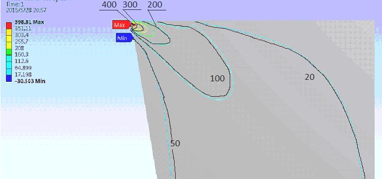
2 3. Research methods. Results of experiments Small thickness of the cutting insert h = 2 mm leads to extremely high (σ 3 = 6866 MPa) compressive stresses near the cutting edge, stresses that exceed the ultimate compressive strength of cemented carbide (WC8Co) (σ UCS = 4200 MPa). It is practically proved by brittle fracture of cutting inserts when its thickness is less than 2 mm [2-5]. Figure 1. Distribution of normal stresses in the cutting wedge for a cutting insert with thickness of 2 mm. Width of the wear-land h f = 0.2 mm Tensile stresses (σ 1 = +542 МПа) are observed on the face surface at a distance equal to approximately four lengths of contact of a chip with a rake surface. The tensile stress value approaches the ultimate tensile strength of cemented carbide (WC8Co) (σ UTS = +750 MPa). High tensile stresses (σ 1 = +542 MPa) are observed on the base of the cutting insert, which value approaches the ultimate tensile strength of cemented carbide BK8. In practice, the results of calculations are justified by brittle fracture of the base of the insert with small thickness [6, 7]. Tensile stresses at the bottom of the base of the insert are not observed (Figure 2b, the base is not displayed, since there are no lines that correspond to σ <100 MPa). Shear stresses τ in the cutting edge were calculated under similar condition (Figure 3). The shear stress near the cutting edge of the cutting insert with small thickness (h=2 mm) exceeds the ultimate shear strength of cemented carbide (Figure 3a), which leads to destruction of a cutting part. The maximum value of the shear stress does not exceed the ultimate shear strength of cemented carbide when thickness of the cutting insert is bigger than 5 mm (Figure 3b). The influence of the cutting insert thickness on the maximum value of normal stresses σ max near the cutting edge is represented in Figure 4. The greatest influence of the cutting insert thickness is observed for h 7 мм (σ 3 = 3000 MPa). This influence reduces significantly with a further increase in the insert thickness, and for h > 12 mm thickness does not influence the magnitude of the normal stress near the cutting edge (σ 3 = MPa). The influence of the cutting insert thickness on maximum value of the shear stress τ max has a similar character (Figure 5), but its influence is sufficiently great for h > 12 mm. 2


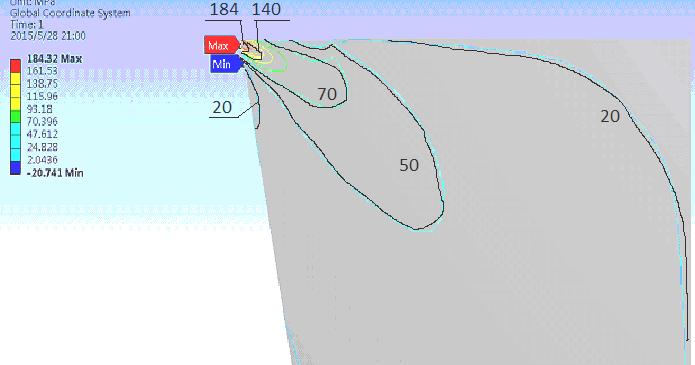
3 a b c d Figure 2. Distribution of normal stresses σ [MPa] in the cutting wedge for a cutting insert with thickness of h: a h = 2 mm; b h = 6 mm; c h = 12 mm; d h = 20 mm. a b c d Figure 3. Distribution of shear stresses τ [MPa] in the cutting edge for a cutting insert with thickness of h: a h = 2 mm; b h = 6 mm; c h = 12 mm; d h = 20 mm. 3
4 Figure 4. Influence of the cutting insert thickness on the maximum value of the principle normal stress in the cutting wedge Figure 5. Influence of cutting insert thickness on the maximum value of the tangential stress in the cutting wedge Relatively low, but elevated stresses ( 3200 > σ MPa) influence the probability of the insert destruction, since the presence of small imperfections in a zone of these stresses can lead to development of a macro-crack with subsequent destruction of the cutting insert. The diagram of relationship between the location of a zone with increased normal stresses ( σ MPa) and insert thickness is presented in Figure 6. The zone with increased stresses is negligibly small for insert thickness h > 12 mm. Figure 6. Influence of cutting insert thickness on the distance from the cutting edge to the zone with increased normal stress (σ 2000 MPa) in the cutting wedge 4
5 4. Conclusion In machining of titanium alloy (Ti6Al2Mo2Cr) with an insert having thickness equal to or less than 5 mm, high compressive stresses, which exceed the ultimate compressive strength of cemented carbide (WC8Co), arise near the cutting edge, which leads to chipping of the major cutting edge. In machining of titanium alloy (Ti6Al2Mo2Cr) with cutting insert thickness equal to or less than 5 mm, tensile stresses, which approach the ultimate tensile strength of cemented carbide, arise on the face and base surfaces of the cutting insert, which increases the probability of cutting insert destruction. In machining of titanium alloy (Ti6Al2Mo2Cr) with a cutting insert having thickness equal to or less than 6 mm high shear stresses arise near the cutting edge, exceeding the ultimate shear strength of cemented carbide and leading to destruction of the major cutting edge. The application of cutting inserts with thickness of more than 6 mm in machining of titanium alloy helps to avoid destruction of easily worn inserts, which are common for finish and semifinish machining [4, 6, 7]. References [1] Kozlov V 2012 Proceedings 7th International Forum on Strategic Technology, IFOST [2] Shaw M 2003 Sadhana [3] Anderson T 1991 CRC Press, Florida [4] Narutaki N et al 1983 CIRP Annals - Manufacturing Technology 32(1) [5] Wang B et al 2013 International journal of Machine Tools & Manufacture [6] Hu J and Chou Y 2007 Wear 263(7-12) [7] Kozlov V and Li X 2015 Applied Mechanics and Materials: Scientific Journal