GEOSYNTHETICS AND. Design and Construction of Pavements Using Geosynthetics-II
|
|
|
- Bernice Stone
- 5 years ago
- Views:
Transcription


1 GEOSYNTHETICS AND REINFORCED SOIL STRUCTURES Design and Construction of Pavements Using Geosynthetics-II P f K R j l Prof K. Rajagopal Department of Civil Engineering IIT Madras, Chennai gopalkr@iitm.ac.in
2 Outline Worked Examples Use of geosynthetics in pavements Construction aspects
3 Field Identification of CBR value Field observation Approximate CBR Value Easily penetrated t with thumb < 2 Moderate effort to penetrate with thumb Indented with thumb Indented with thumb nail 6 16 Difficult to indent with thumb nail > 16
4 US ARMY CORPS of Engineers generalized equation for any rut depth and loading (N<10000): h o log N C log P 0.63 u r Where, h o = base course thickness under traffic (m) N = Number of traffic passes P = axle load in Newtons r = rut depth (m) c u = undrained cohesive strength (Pa)
5 Worked Example Estimate the granular base thickness for the following cases: i) N=1000, P=80, N, r=0.3m, 03 C uu = 30, Pa Substituting these values in the above equation, we get the pavement thickness as 0.46m ii) N=10,000, P=80,000 N, r=0.3m, C uu =30,000Pa Thickness of base = 0.64 m
6 Comparison of base thickness for different cases N P (N) r (m) C uu (Pa) Thickness (m) , , , , , , , , , ,


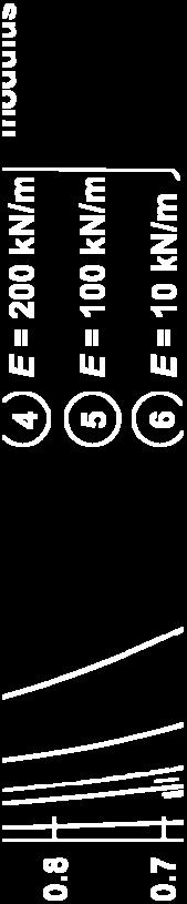
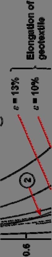
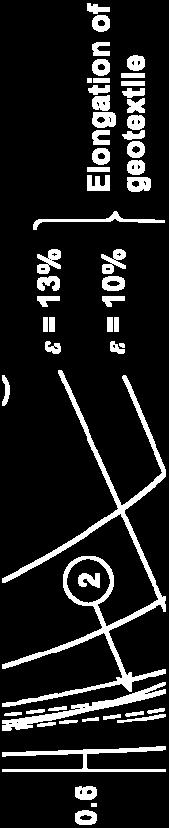
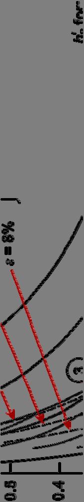
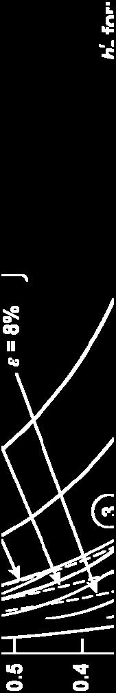

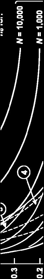
7 P = 80 kn Pc = 480 kpa r = 300 mm h o depends on CBR & no. of passes h depends on reinforcement modulus
8 Example on the use of Design chart: Design the thickness of the base layer for the following data: No. of load passes = Standard axle load = 80 kn CBR value of subgrade = 1 Allowable rut depth = 0.3m Modulus of the geosynthetic = 200 kn/m Tyre inflation pressure = 480 kpa From the chart for CBR=2, N=10,000: h o 0.57 m Reduction in thickness due to reinforcement, h = 0.25m Thickness to be provided for reinforced case p = = 0.32 m 350 mm
9 Modified CBR method of design adapted by Koerner (1999) The laboratory CBR test is modified by introducing the geosynthetic ti layer and the modified d CBR with reinforcement is determined. Using the empirical equation, the thickness of base layer is estimated h P A 3.24logC CBR 2030 h = base layer thickness in mm C = no. of load passes P = equivalent single wheel load (N) A = tyre contact area (mm 2 ) CBR value with and without t reinforcement is used in the above equation
10 Example: Design the thickness of pavement for subgrade soaked CBR=1.0, N=10000, ESWL = 40 kn Tyre contact area is mm. The CBR value with reinforcement layer = 3 h = (3.24 log )*(40000/(36*1)-(300*450/2030) 1/2 = * = 490 mm Pavement thickness with geosynthetic layer (use CBR=3) h = (3.24 log )*(40000/(36*3)-(300*450/2030) 1/2 = * = 265 mm Reduction in thickness = = 225 mm
11 Use of Geosynthetics h i hl i l f ll Geosynthetics help in several ways as follows: o Reinforcement helps in reducing subgrade stresses and prevents cracking of pavement due to swelling of foundation soil o Separator prevents mixing up of layers o Filter layer prevents piping phenomenon o Drainage layer provides for safe disposal of water o Asphalt reinforcement helps in preventing the reflection cracks
12 Geotextile Function as function of CBR (Koerner 1999) Function Unsoaked CBR Soaked CBR Separation 8 3 Stabilisation Reinforcement & 3 1 separation
13 Geosynthetic Stabilisation of Roads on Expansive clays Identification based on liquid limit (LL > 50%), Shrinkage limit (<12%) Differential Free Swell Index (>50%) Stabilisation lime mixing, lime columns, lime columns, cement stabilisation, soil reinforcement
14 Desirable geosynthetic properties Longitudinal crack on pavements over expansive clays Biaxial geogrids g % Open area > 70% High stiffness at low strain levels l (200 to 300 kn/m) Good junction strength Zornberg and Gupta (2009)
15 Mechanisms of pavement deflection over expansive clays a: shrinkage during dry season b. Heaving during wet season Zornberg and Gupta (2009)
16 a. Geogrid reinforced section b. unreinforced section g b. c. Geogrid reinforced section Zornberg and Gupta (2009)

17 Repair of Asphalt Pavements Relatively thin asphalt overlay is constructed on existing pavement (with surface cracks) in order to reduce water intrusion, reduce surface roughness, improve skid resistance and increase the structural capacity. In short time, the cracks from the old pavement propagate to the surface of overlay. This process is called reflection cracking phenomenon
18 Pavement surface with overlay fabric Typical cracks on the pavement surface Surface without overlay fabric P f f h lt t ith d ith t Performance of asphalt pavements with and without overlay fabrics (Techfab India Industries Ltd. Mumbai)


19 U f l f b i f t ti t Use of overlay fabrics for protecting pavements (Techfab India Industries Ltd. Mumbai)
20 Reflection Cracking Propagation of vertical cracks from old pavement to the new overlays Khodaii et al. (2009)
21 Laboratory repeated load test to investigate reflection cracks pressure = 690 kpa Khodaii et al. (2009)
22 Khodaii et al. (2009)
23 Khodaii et al. (2009)
24 Rate of crack growth lower for reinforced specimens Rate of crack growth least for reinforcement in bottom third Crack growth with number of loading cycles Khodaii et al. (2009)
25 No. 1 -old concrete pavement & No.2 -old asphalt pavement Service life with different crack widths & position of reinforcement Khodaii et al. (2009)
26 No. 1 - old concrete pavement & No.2 - old asphalt pavement Khodaii et al. (2009)
27 Typical MORTH Specifications for Paver Fabrics Property ASTM Standard Specification Grab tensile strength ASTM D N Grab Elongation ASTM D % Asphalt Retention Texas DOT kg/m2 Melting point ASTM D C
28 aggregate layer geotextile separator subgrade soil Prevents ents the intermixing, ing prevents piping, strength of aggregate is preserved Separation Function in a pavement layer
29 Separation function of geosynthetics Loss of aggregate into soft ground Stable aggregate layer due to separation
30 Typical Specifications for separation fabric (AASHTO 1990) Class of loading Grab strength < 50% Grab strength > 50% Puncture resistanc e < 50% ance Puncture resistanc e > 50% Tear strength Tear strength Class-I 1400 N 900 N 500 N 350 N 500 N 350 N Class-II N Class-III N
31 Drainage function of a geotextile layer ingress of water into pavement layers flow of water flow of water drain drain Thick geotextile with good drainage properties is used at interface
32 Filtration Function Water coming out leaving behind the fine soil particles intact Geotextile layer acting as a filter
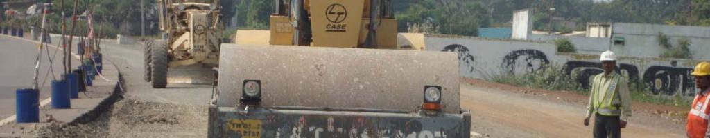
33 Installation of Geosynthetic Level & Prepare the ground Spread the geosynthetic Dump the aggregate on geosynthetic Spread the aggregate Compaction by suitable means

34 Prepare the Ground remove the stumps boulders etc ; remove the stumps, boulders, etc.; fill in low spots.


35 Spread the Geosynthetic on prepared ground Use suitable pins to hold down the geosynthetic no p g y wrinkles in the geosynthetic

36 Forming a Curve Using Folds
37 Forming a Curve Using Cut Pieces


38 Back Dump Aggregate g onto previously placed aggregate. Do not drive on the geosynthetic. Maintain 150 mm to 300 mm cover between truck tires and geosynthetic.
39 Back Dumping Aggregate g Minimum cover of 150 to 200 mm soil above geosynthetic
40 Spreading Aggregate g


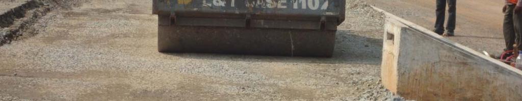

41 Compact the Aggregate using suitable compaction equipment.


42