Deposition Behavior and Superheater Corrosion under Coal Fired Oxyfuel Conditions
|
|
|
- Bennett Miles
- 5 years ago
- Views:
Transcription


1 Institute of Combustion and Power Plant Technology Prof. Dr. techn. G. Scheffknecht Special Workshop on Oxyfuel Combustion Addressing SO2/SO3/Hg and Corrosion Issues London Jan. 25 th 26 th, 2011 Deposition Behavior and Superheater Corrosion under Coal Fired Oxyfuel Conditions Gosia Stein-Brzozowska Jörg Maier Günter Scheffknecht
2 Content Motivation Experimental part Procedure: Samples preparation Test facilities Applied fuels Chosen materials Test conditions Analytics Results and conclusions Fly ash transformations Corrosion Future prospects
3 Content Motivation Experimental part Procedure: Samples preparation Test facilities Applied fuels Chosen materials Test conditions Analytics Results and conclusions Fly ash transformations Corrosion Future prospects
4 Motivation Composition of oxy-fuel vs conventional air combustion atmosphere significantly different: CO 2 is higher by factor > 5 (16 92 % vol. dry) SO 2 is higher by factor 3 5 H 2 O is higher by factor Compensate the efficiency loss (ASU, CO2-CU: 7 12%) higher steam parameters (USC-PP) Changes in corrosion mechanisms and rates of the boiler heat exchangers
5 Content Motivation Experimental part Procedure: Samples preparation Test facilities Applied fuels Chosen materials Test conditions Analytics Results and conclusions Fly ash transformations Corrosion Future prospects

6 Experimental part > Test facilities short-term tests up to 100 h long-term tests Real fly ash Gas composition: SO 2, CO 2, H 2 O, O 2, NO x
 Coal C: hard coal of alumino-silicatic character (S raw =0,47) sample Coal A Coal B Coal C immediate analysis water content (N 2 +106 C), % volatiles (N 2 +900 C), % ash (O 2 +815 C), % fixed")
7 Experimental part > Applied fuels 3 different mineral systems were chosen: Coal A: pre-dried lignite of basic character (S raw =0,48) Coal B: pre-dried lignite of alumino-silicatic character (S raw =1,46) Coal C: hard coal of alumino-silicatic character (S raw =0,47) sample Coal A Coal B Coal C immediate analysis water content (N C), % volatiles (N C), % ash (O C), % fixed C (calcul.), % an* an* an* 9,8 10,1 1,7 48,8 41,5 23,8 5,2 17,4 15,1 36,2 31,0 59,4 *an coal as analysed

![Mass Flow [kg/h] Excess](/docs-images/92/108804061/images/8-2.jpg "Oxygen (λ ) Recirculation")
![Flue Gas [%] 36 38 1,3 1,2-54](/docs-images/92/108804061/images/8-3.jpg "8 11 15 Sampling BKE AK LuVo")
8 Experimental Frame Operation Parameters Air Oxyfuel Fuel Mass Flow [kg/h] Excess Oxygen (λ ) Recirculation Flue Gas [%] ,3 1, Sampling BKE AK LuVo E1, E2, E3 8


9 Fly ash collection Tempered corrosion probe tubes/pipes, primary deposition layer Fly ash suction probes total fly ash Ceramic samplers secondary layer 9


10 Experimental part > Alloys Three Nickel basis materials were chosen for the tests; C-content reaches max. 0,06%-m N1 before exposures.
11 Experimental part > Test conditions Long time exposures: Temperature: 750 C Exposure time: 350 h Gas atmosphere: compound unit Coal C Coal A air oxy-fuel air oxy-fuel O 2 [%-vol.] 4,5 4,5 4,5 4,5 CO 2 [%-vol.] 16,0 80,0 16,0 64,0 N 2 [%-vol.] 72,0 0,0 64,0 0,0 SO 2 [%-vol.] 0,5 1,5 0,5 1,5 H 2 O [%-vol.] 7,0 14,0 15,0 30,0
12 Content Motivation Experimental part Procedure: Samples preparation Test facilities Applied fuels Chosen materials Test conditions Analytics Results and conclusions Fly ash transformations Corrosion Future prospects
![Results and Discussions Level 8 CO CO 2 SO 2 Temperature Absolute Sulphur concentration in FA [%] [%] [ppm] [ C] [%] Air 0,12 14,4 497 1163 < 0,3 Oxy-fuel 0,12 81,8 1377 1172 < 0,3 Level 11 CO CO 2](/docs-images/92/108804061/images/13-1.jpg "SO 2 Temperature Absolute Sulphur concentration in FA [%] [%] [ppm] [ C] [%] Air 0,1 14,8 512 1072 0,42 Oxy-fuel 0,1 81,7 1273 1057 < 0,3 BKE CO CO 2 SO 2 Temperature Absolute Sulphur concentration")
13 Results and Discussions Level 8 CO CO 2 SO 2 Temperature Absolute Sulphur concentration in FA [%] [%] [ppm] [ C] [%] Air 0,12 14, < 0,3 Oxy-fuel 0,12 81, < 0,3 Level 11 CO CO 2 SO 2 Temperature Absolute Sulphur concentration in FA [%] [%] [ppm] [ C] [%] Air 0,1 14, ,42 Oxy-fuel 0,1 81, < 0,3 BKE CO CO 2 SO 2 Temperature Absolute Sulphur concentration in FA [ppm] [%] [ppm] [ C] [%] Air , ,38 Oxy-fuel ,1 13


14 Results and Discussions Combustion chamber FG cleaning path Combustion chamber FG cleaning path Sulphur enrichment has a similar tendency in air and oxy-fuel combustion in oxy-fuel compared to air combustion: more Sulphur found at the end of the combustion chamber (BKE) and ESP 2 in oxy-fuel in ESP 3 different distribution of the mineral phases possible influence of recirculation of very fine PM 14


15 Results and Discussions Particle size distribution in the combustion chamber Particle size distribution in the FG path Particle size distribution determination by Malvern Smaller particles in oxy-fuel in the electrostatic precipitator Particle size distribution determination by Malvern Clusters of smaller stickyparticles in oxy-fuel in the combustion chamber in the means of SO2 adsorption higher surface area 15

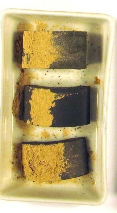
16 Results and conclusions > 24 h, KSVA (material C-HC-A_7) (material C-HC-O_1) (material C-HC-A_7) (material C-HC-O_1) air-case Ca and S Ca and S oxy-fuel-case concentration Ca and C Ca and C air-case oxy-case air-case oxy-fuel-case higher sulphanation of the fly ash particles under oxy-fuel due to the much higher p i,so2 carbonation of the fly ash particles under oxy-fuel is bigger due to the much higher p i,co2

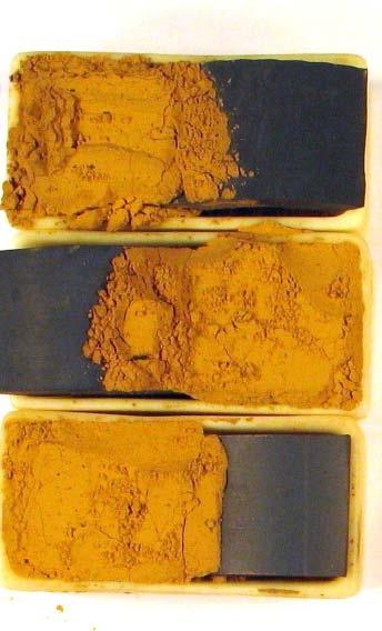
17 Results and Discussions > 350 h, lab oxy-fuel air-case simultaneous presence of Ca, Fe and C as well as Ca, Fe and S carbonitization and sulphanation carbonation of the particles increases significantly with time under oxy-fuel due to the much higher p i,co2 equilibrium thermodynamic calculations suggest that Na, K, Ca, Mg and Fe will tend to form sulphates, rather than carbonates on cooling in flue gas (Wigley, 2008) 17
18 Results and conclusions > Ash transformation Under oxy-fuel compared to conventional air combustion: higher sulphation and over the time as well carbonation of the fly ash particles due to the much higher p i,so2 p i,co2 clusters of smaller sticky particles in the combustion chamber in the means of SO 2 higher adsorption surface low slagging and fouling indexes for coal C; moreover they do not differ significantly between air and oxy-fuel fly ashes/deposits sulphur enrichment has a similar tendency smaller fly ash particles found in all 3 ESP compartments more sulphur found at the end of the combustion chamber (BKE) and ESP 2 in ESP 3 different distribution of the mineral phases possible influence of recirculation of very fine PM
19 Contents Motivation Experimental part Procedure: Samples preparation Test facilities Applied fuels Chosen materials Test conditions Analytics Results and conclusions Fly ash transformations Corrosion Future prospects AB-A_304_670C_231h_2


20 Alloy N1 after 350h at 750 C air-case oxy-fuel BSE BSE MAE and O MAE and O S S N1-A_350C_750h_3 N1-O_350C_750h_1 concentration higher growth of oxide-scale under oxy-fuel conditions; internal oxidation was noticed already in the pre-exposed state; no sulphur-front recognized 20

21 Alloy N2 after 350h at 750 C air-case oxy-fuel BSE BSE MAE and O MAE and O S S N2-A_350C_750h_1 N2-O_350C_750h_3 concentration higher growth of oxide-scale under oxy-fuel conditions; internal oxidation was noticed already in the pre-exposed state; first signs of sulphur front 21


22 Alloy N3 after 350h at 750 C air-case oxy-fuel BSE BSE MAE and O MAE and O S S N3-A_350C_750h_1 N3-O_350C_750h_1 concentration higher growth of oxide-scale under oxy-fuel conditions; internal oxidation was noticed already in the pre-exposed state; barely seen sulphur front


23 Results and conclusions > Corrosion In oxy-fuel compared to air-case: Sulphate-induced corrosion sulphate induced corrosion was awaited and even though SO2 was higher by a factor of 3 compared to the conventional air combustion conditions, barely any evidences of sulphate induced corrosion were noticed after 350 h at material temperature of 750 C Differences in the oxide scale formation and C-enrichment C enrichment in oxy-fuel-case was not clearly stated higher growth of oxide-scale under oxy-fuel conditions; reason could be much higher p i,h2o internal oxidation was noticed already in the pre-exposed state; reason for that could be high gratitude of materials matrix and tension stresses at their surfaces protective Cr2O3 N1-A_350C_750h N1-O_350C_750h
24 Contents Motivation Experimental part Procedure: Samples preparation Test facilities Applied fuels Chosen materials Test conditions Analytics Results and conclusions Fly ash transformations Corrosion Future prospects
25 Future prospects Long-term laboratory exposures with chosen salts under oxy-fuel conditions (martensitic, austenitic and Ni-based alloys) Long-term laboratory exposures of rings from corrosion probe exposed to oxy-coal A and oxy-coal B combustion (martensitic, austenitic and Ni-based alloys) Fly ash analysis from the combustion of coal B in both air- and oxy-fuel conditions (measuring campaign finished last week) Evaluation of measurements under oxy- and conventional combustion of coal A are running Long-term tests with rings from the corrosion probe resulting from combustion of coal A and B under oxy-fuel conditions 25
26 Future focus waterwall corrosion (reductive atmosphere in oxy-fuel) SO2 H2S SO2+H2S O (SO 2 +H 2 S) max SO 2, H 2 S [ppm] Air O 2 [Vol. %] SO2, H2S [ppm] OF O 2 [Vol. %] (SO 2 +H 2 S) max ,5 1 1,5 2 2, ,5 1 1,5 2 2,5 0 Distance from burner [m] Distance from burner [m] Concentration profiles for gaseous sulphur compounds and oxygen (Lusatian lignite) Source: Scheffknecht G., Maier J., Firing Issues Related to the Oxyfuel Process, VGB Power Tech 11/2008 p
27 Thank you for your attention Questions? 27
28 Special thanks Special thanks to my colleagues, without whom the work at the 0,5 MW test rig at IFK wouldn t have been possible Joerg Maier, for the long discussion on these results Dr. Thomas Theye, who introduced me to electron microscopy 28
 XRD SEM-EDX/WDX Alloy / Deposition SEM-EDX/WDX BSE images")
 using a graphical programme Application")

29 Experimental part > Analysis Fly ash analysis Main elements (ICP) XRD SEM-EDX/WDX Alloy / Deposition SEM-EDX/WDX BSE images element distribution maps Graphical analysis of the element distribution maps (Maps) using a graphical programme Application of logical functions Cr + Fe + Ni + = MAE* MAE and O simultaneous presence of oxygen and MAE in the sample * MAE = Main Alloying Elements 29

30 Experimental part > Test facilities / flue gas Inflame Measurements Gas emissions Gas temperature Fly ash collection Sampling Ash, HCl, SO3 Continuous gas emission measurements
31 Results and Discussions Acid Oxides Base Oxides SiO2 [%] Al2O3 [%] TiO2 [%] Fe2O3 [%] CaO [%] MgO [%] Na2O [%] K2O [%] Air Hard coal Index Formula Indication Slagging R s = (B/A) * S d S d = % S in dry fuel Fouling F u = (B/A) * (Na 2 O + K 2 O) Leve l 8 Level 11 Slagging and fouling index R s < 0,6 low slagging inclination F u 0,6 low fouling inclination F u = 0,6 40 high (air case) Level 15 BKE AK LuVo E1 E2 E3 Slagging index 0, ,08 0,39 0,33 0,45 0,24 0,15 0,31 0,16 Fouling index 0,42 0,29 0,25 0,28 0,41 0,86 0,79 0,29 0,48 0,39 Oxy-fuel Slagging index 0, ,39 0,19 0,11 0,14 0,04 0,15 0,06 Fouling index 0, ,03 0,59 0,25 0,26 0,24 0,07 0,25 0,09 31
 170 160 150 140 130 120 110 100 90 80 70 60 50 40 30 20 10 0 20 30 40 50")
 - Time Started: 3 s - 2 Operations: X Offset 0.208 X Offset 0.156 Background 0.309,1.000 Background 5.623,1.000 Background 0.309,1.000 Background 0.046,1 e:\user\ivd\stein\elcer-oxy_eb8_ksva20_09.")
 - Time Started: 0 s Operations: Y Scale Add 2 Y Scale Add 1 Y Scale Add 2 Y Scale Add 83 Background 0.309,1.000 Import 79-1910 (C) - Quartz - SiO2 - Y: 61.34 % - d x by: 1. - WL: 1.")
32 Results and Discussions e:\user\ivd\stein\elcer-air_eb8_ksva20_09.raw XRD: Ash Level 8 Air / Oxy-fuel XRD: Ash Level 15 Air / Oxy-fuel Lin (Counts) Theta - Scale e:\user\ivd\stein\elcer-air_eb8_ksva20_09.raw - File: ElCer-Air_Eb8_KSVA20_09.RAW - Type: 2Th/Th locked - Start: End: Step: Step time: 2. s - Temp.: 25 C (Room) - Time Started: 3 s - 2 Operations: X Offset X Offset Background 0.309,1.000 Background 5.623,1.000 Background 0.309,1.000 Background 0.046,1 e:\user\ivd\stein\elcer-oxy_eb8_ksva20_09.raw - File: ElCer-Oxy_Eb8_KSVA20_09.RAW - Type: 2Th/Th locked - Start: End: Step: Step time: 2. s - Temp.: 25 C (Room) - Time Started: 0 s Operations: Y Scale Add 2 Y Scale Add 1 Y Scale Add 2 Y Scale Add 83 Background 0.309,1.000 Import (C) - Quartz - SiO2 - Y: % - d x by: 1. - WL: I/Ic PDF n.a. - I/Ic User n.a. - S-Q n.a (C) - Mullite - Al(Al1.272Si0.728O4.864) - Y: % - d x by: 1. - WL: I/Ic PDF n.a. - I/Ic User n.a. - S-Q n.a (C) - Labradorite - from Lake county - Ca0.65Na0.35(Al1.65Si2.35O8) - Y: % - d x by: 1. - WL: I/Ic PDF n.a. - I/Ic User n.a. - S-Q n.a (C) - Cristobalite, syn - SiO2 - Y: % - d x by: 1. - WL: I/Ic PDF n.a. - I/Ic User n.a. - S-Q n.a. level 8 more mullite was noticed in oxy-fuel-case however only in the air-case cristoballite and labradorite was found. level 15, BKE in both combustion modes quartz, anhydrite, hematite and much less mullite were found. the ESP quartz, mullite, anhydrite and some hematite were found. Moreover more mullite was found in the ESP than in the fly ashes collected in the combustion chamber. 32
33 Results and conclusions > Fly ashes (FA) > Mineral phases No significant differences between air and oxyfuel in the composition of the minerals phases. Only the concentrations differ XRD: Hard coal-fa-oxy XRD: Lignite-FA-oxy mullite 2 quartz 3 anhydrite 4 hematite 5 brownmillerite 6 - periclase different mineral phases occur in both fuels, however anhydrite and quartz are present in both fuel fly ashes
 > XRD")
34 Hard coal fly ash (E) > XRD
35 Lignite fly ash (E) > XRD
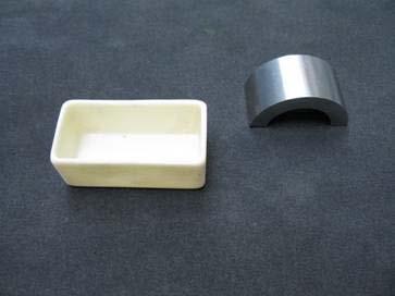
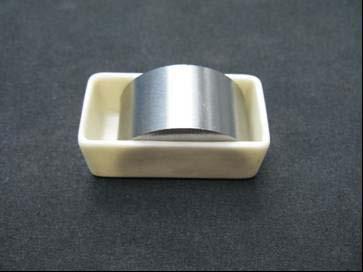
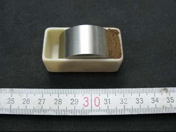

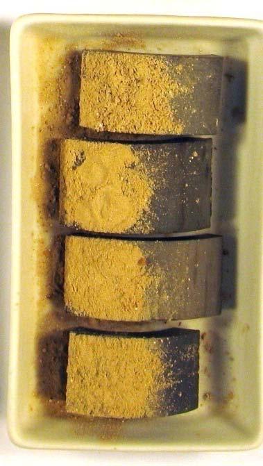

36 Samples preparation