Workshop RIETVELD REFINEMENT OF DIFFRACTION PATTERNS Program Monday June 1st, Introduction to Rietveld refinement S.
|
|
|
- Tamsyn Wheeler
- 5 years ago
- Views:
Transcription
1 Workshop RIETVELD REFINEMENT OF DIFFRACTION PATTERNS Program Monday June 1st, Introduction to Rietveld refinement S.Enzo Università di Sassari X-ray diffraction for bulk samples and thin films M.Baricco Università di Torino MAUD: Materials Analysis Using Diffraction L.Lutterotti Università di Trento Lunch
2 The Powder Diffraction Approaches Difficulties in the basics (the language spoken is a mixture of physics and mathematics). The chemistry students are freightened! Difficulties in accessing the instrument. One common solution: Send a student to a summer school nominate him the expert of crystallography of the group. The learning process may take several years.


3 What is diffraction by solids Why it deals with X-rays, neutrons and electrons? Diffraction is the effect following the interaction of an EM wave with an object having size dimension comparable with the period of the wave

4 X-Ray Diffraction is used to study crystalline materials X-rays scatter off of the atoms in a sample If those atoms are systematically ordered, the scattered X-rays tell us: what atoms are present how they are arranged

 and α, β and γ angles between a,b and c are lattice constants")
5 First we need some basics of crystallography A crystal consists of a periodic arrangement of the unit cell into a lattice. The unit cell can contain a single atom or atoms in a fixed arrangement. a,b and c (length) and α, β and γ angles between a,b and c are lattice constants or parameters which can be determined by XRD.
 planes of atoms in NaCl The (220) planes of atoms in NaCl Parallel planes of atoms intersecting the unit cell are used to define directions and distances")
6 Crystalline materials are characterized by the orderly periodic arrangements of atoms. The (200) planes of atoms in NaCl The (220) planes of atoms in NaCl Parallel planes of atoms intersecting the unit cell are used to define directions and distances in the crystal. These crystallographic planes are identified by Miller indices.
7 Examples of Miller Planes b a
8 Examples of Miller Planes b a
9 Examples of Miller Planes b a
10 Examples of Miller Planes h=1, k=-1 b a
11 Examples of Miller Planes h=1, k=-1 b a
12 Examples of Miller Planes h=1, k=-1 h=1, k=0 b a
13 Examples of Miller Planes h=1, k=-1 h=1, k=0 b a
14 Examples of Miller Planes h=1, k=-1 h=1, k=0 h=1, k=-2 b a
15 Examples of Miller Planes h=1, k=-1 h=1, k=0 h=1, k=-2 b a
16 Examples of Miller Planes h=1, k=-1 h=1, k=0 h=1, k=-2 h=4, k=-1 b a
17 Examples of Miller Planes h=1, k=-1 h=1, k=0 h=1, k=-2 h=4, k=-1 b a
18 Examples of Miller Planes h=1, k=-1 h=1, k=0 h=1, k=-2 h=4, k=-1 h=2, k=1 b a
19 Examples of Miller Planes h=1, k=-1 h=1, k=0 h=1, k=-2 h=4, k=-1 h=2, k=1 Note that the 2, 2 and b a
20 Examples of Miller Planes h=1, k=-1 h=1, k=0 h=1, k=-2 h=4, k=-1 h=2, k=1 Note that the 2, 2 and -2, -2 planes are identical b a
21 Bragg s law The diffraction process occurs when the Bragg s law (condition) is satisfied. It is expressed as: Where λ is the wavelength of x-rays d is the interplanar spacing θ is the x-ray angle n is an integer
22 Lattices In 1848, Auguste Bravais demonstrated that in a 3-dimensional system there are fourteen possible lattices A Bravais lattice is an infinite array of discrete points with identical environment seven crystal systems + four lattice centering types = 14 Bravais lattices Lattices are characterized by translation symmetry Auguste Bravais ( )
23 Crystal system Crystals are grouped into seven crystal systems, according to characteristic symmetry of their unit cell. The characteristic symmetry of a crystal is a combination of one or more rotations and inversions. Recall that the unit cell of a crystal is the smallest 3-D geometric figure that can be stacked without rotation to form the lattice. The asymmetric unit is the smallest part of a crystal structure from which the complete structure can be built using space group symmetry. The asymmetric unit may consist of only a part of a molecule, or it can contain more than one molecule, if the molecules not related by symmetry.
24 Specifically 3-D crystals may be arranged in 7 crystal systems cubic monoclinic orthorhombic tetragonal triclinic trigonal hexagonal Crystal System External Minimum Symmetry Unit Cell Properties Triclinic None a, b, c, al, be, ga, Monoclinic One 2-fold axis, to b (b unique) a, b, c, 90, be, 90 Orthorhombic Three perpendicular 2-folds a, b, c, 90, 90, 90 Tetragonal One 4-fold axis, parallel c a, a, c, 90, 90, 90 Trigonal One 3-fold axis a, a, c, 90, 90, 120 Hexagonal One 6-fold axis a, a, c, 90, 90, 120 Cubic Four 3-folds along space diagonal a, a,,a, 90, 90, 90
25 Proper symmetry elements in 3D Rotation axes (by 60, 90, 120, or 180 ) Notated: 6, 4, 3, and 2, respectively Screw Axes (translation and rotation) Notated: 6 1, 6 2, 6 3, 6 4, 6 5 ; 4 1, 4 2, 4 3 ; 3 1, 3 2 ; and 2 1 (Translation) Reflection planes Glide reflection planes (reflection and translation) Inversion points Rotary inversion axes (rotation and inversion)

26 Categories of Space Groups
27 The combination of all available symmetry operations (32 point groups), together with translation symmetry, within the all available lattices (14 Bravais lattices) lead to 230 Space Groups that describe the only ways in which identical objects can be arranged in an infinite lattice. The International Tables list those by symbol and number, together with symmetry operators, origins, reflection conditions, and space group projection diagrams. An interactive tutorial on Space Groups can be found on-line in Bernhard Rupp s Crystallography 101 Course:
28 Generating a Crystal Structure from its Crystallographic Description Using the space group information contained in the International Tables we can do many things. One powerful use is to generate an entire crystal structure from a brief description. Let us consider the description of the crystal structure of NaCl. Space Group = Fm 3m a = 5.44 Å Atomic Positions Cl 1:(0.0,0.0,0.0), 2:(0.5,0.5,0.0), 3: (0.5,0.0,0.5), 4:(0.0,0.5,0.5) Na 1:(0.5,0.5,0.5), 2:(0.0,0.0,0.5), 3: (0.0,0.5,0.0), 4:(0.5,0.0,0.0) Using the face centering generators (0,0,0), (½,½,0), (½,0,½), (0,½,½) together with the coordinates of each Wyckoff site we can generate the fractional coordinates of all atoms in the unit cell.
29 Summary:
30 With no knowledge of the symmetry diagram we can identify the crystal system from the space group symbol. Summary:
31 Summary: Cubic The secondary symmetry symbol will always be either 3 or -3 (i.e. Ia3, Pm3m, Fd3m) Tetragonal The primary symmetry symbol will always be either 4, (-4), 4 1, 4 2 or 4 3 (i.e. P , I4/m, P4/mcc) Hexagonal The primary symmetry symbol will always be a 6, ( 6), 6 1, 6 2, 6 3, 6 4 or 6 5 (i.e. P6mm, P6 3 /mcm) Trigonal The primary symmetry symbol will always be a 3, ( 3), 3 1 or 3 2 (i.e P3 1 m, R3, R3c, P3 1 2) Orthorhombic All three symbols following the lattice descriptor will be either mirror planes, glide planes, 2-fold rotation or screw axes (i.e. Pnma, Cmc2 1, Pnc2) Monoclinic The lattice descriptor will be followed by either a single mirror plane, glide plane, 2-fold rotation or screw axis or an axis/plane symbol (i.e. Cc, P2, P2 1 /n) Triclinic The lattice descriptor will be followed by either a 1 or a ( 1).
32 With no knowledge of the symmetry diagram we can identify the crystal system from the space group symbol. Summary: Cubic The secondary symmetry symbol will always be either 3 or -3 (i.e. Ia3, Pm3m, Fd3m)
33 Summary: Tetragonal The primary symmetry symbol will always be either 4, (-4), 4 1, 4 2 or 4 3 (i.e. P , I4/m, P4/mcc) Hexagonal The primary symmetry symbol will always be a 6, ( 6), 6 1, 6 2, 6 3, 6 4 or 6 5 (i.e. P6mm, P6 3 /mcm) Trigonal The primary symmetry symbol will always be a 3, ( 3), 3 1 or 3 2 (i.e P3 1 m, R3, R3c, P3 1 2) Orthorhombic All three symbols following the lattice descriptor will be either mirror planes, glide planes, 2-fold rotation or screw axes (i.e. Pnma, Cmc2 1, Pnc2) Monoclinic The lattice descriptor will be followed by either a single mirror plane, glide plane, 2-fold rotation or screw axis or an axis/plane symbol (i.e. Cc, P2, P2 1 /n) Triclinic The lattice descriptor will be followed by either a 1 or a ( 1).
34 With no knowledge of the symmetry diagram we can identify the crystal system from the space group symbol. Summary: Cubic The secondary symmetry symbol will always be either 3 or -3 (i.e. Ia3, Pm3m, Fd3m) Tetragonal The primary symmetry symbol will always be either 4, (-4), 4 1, 4 2 or 4 3 (i.e. P , I4/m, P4/mcc)
35 Summary: Hexagonal The primary symmetry symbol will always be a 6, ( 6), 6 1, 6 2, 6 3, 6 4 or 6 5 (i.e. P6mm, P6 3 /mcm) Trigonal The primary symmetry symbol will always be a 3, ( 3), 3 1 or 3 2 (i.e P3 1 m, R3, R3c, P3 1 2) Orthorhombic All three symbols following the lattice descriptor will be either mirror planes, glide planes, 2-fold rotation or screw axes (i.e. Pnma, Cmc2 1, Pnc2) Monoclinic The lattice descriptor will be followed by either a single mirror plane, glide plane, 2-fold rotation or screw axis or an axis/plane symbol (i.e. Cc, P2, P2 1 /n) Triclinic The lattice descriptor will be followed by either a 1 or a ( 1).
36 With no knowledge of the symmetry diagram we can identify the crystal system from the space group symbol. Summary: Cubic The secondary symmetry symbol will always be either 3 or -3 (i.e. Ia3, Pm3m, Fd3m) Tetragonal The primary symmetry symbol will always be either 4, (-4), 4 1, 4 2 or 4 3 (i.e. P , I4/m, P4/mcc) Hexagonal The primary symmetry symbol will always be a 6, ( 6), 6 1, 6 2, 6 3, 6 4 or 6 5 (i.e. P6mm, P6 3 /mcm)
37 With no knowledge of the symmetry diagram we can identify the crystal system from the space group symbol. Summary: Cubic The secondary symmetry symbol will always be either 3 or -3 (i.e. Ia3, Pm3m, Fd3m) Tetragonal The primary symmetry symbol will always be either 4, (-4), 4 1, 4 2 or 4 3 (i.e. P , I4/m, P4/mcc) Hexagonal The primary symmetry symbol will always be a 6, ( 6), 6 1, 6 2, 6 3, 6 4 or 6 5 (i.e. P6mm, P6 3 /mcm) Trigonal The primary symmetry symbol will always be a 3, ( 3), 3 1 or 3 2 (i.e P3 1 m, R3, R3c, P3 1 2)
38 With no knowledge of the symmetry diagram we can identify the crystal system from the space group symbol. Summary: Cubic The secondary symmetry symbol will always be either 3 or -3 (i.e. Ia3, Pm3m, Fd3m) Tetragonal The primary symmetry symbol will always be either 4, (-4), 4 1, 4 2 or 4 3 (i.e. P , I4/m, P4/mcc) Hexagonal The primary symmetry symbol will always be a 6, ( 6), 6 1, 6 2, 6 3, 6 4 or 6 5 (i.e. P6mm, P6 3 /mcm) Trigonal The primary symmetry symbol will always be a 3, ( 3), 3 1 or 3 2 (i.e P3 1 m, R3, R3c, P3 1 2) Orthorhombic All three symbols following the lattice descriptor will be either mirror planes, glide planes, 2-fold rotation or screw axes (i.e. Pnma, Cmc2 1, Pnc2)
39 With no knowledge of the symmetry diagram we can identify the crystal system from the space group symbol. Summary: Cubic The secondary symmetry symbol will always be either 3 or -3 (i.e. Ia3, Pm3m, Fd3m) Tetragonal The primary symmetry symbol will always be either 4, (-4), 4 1, 4 2 or 4 3 (i.e. P , I4/m, P4/mcc) Hexagonal The primary symmetry symbol will always be a 6, ( 6), 6 1, 6 2, 6 3, 6 4 or 6 5 (i.e. P6mm, P6 3 /mcm) Trigonal The primary symmetry symbol will always be a 3, ( 3), 3 1 or 3 2 (i.e P3 1 m, R3, R3c, P3 1 2) Orthorhombic All three symbols following the lattice descriptor will be either mirror planes, glide planes, 2-fold rotation or screw axes (i.e. Pnma, Cmc2 1, Pnc2) Monoclinic The lattice descriptor will be followed by either a single mirror plane, glide plane, 2-fold rotation or screw axis or an axis/plane symbol (i.e. Cc, P2, P2 1 /n)
40 With no knowledge of the symmetry diagram we can identify the crystal system from the space group symbol. Summary: Cubic The secondary symmetry symbol will always be either 3 or -3 (i.e. Ia3, Pm3m, Fd3m) Tetragonal The primary symmetry symbol will always be either 4, (-4), 4 1, 4 2 or 4 3 (i.e. P , I4/m, P4/mcc) Hexagonal The primary symmetry symbol will always be a 6, ( 6), 6 1, 6 2, 6 3, 6 4 or 6 5 (i.e. P6mm, P6 3 /mcm) Trigonal The primary symmetry symbol will always be a 3, ( 3), 3 1 or 3 2 (i.e P3 1 m, R3, R3c, P3 1 2) Orthorhombic All three symbols following the lattice descriptor will be either mirror planes, glide planes, 2-fold rotation or screw axes (i.e. Pnma, Cmc2 1, Pnc2) Monoclinic The lattice descriptor will be followed by either a single mirror plane, glide plane, 2-fold rotation or screw axis or an axis/plane symbol (i.e. Cc, P2, P2 1 /n) Triclinic The lattice descriptor will be followed by either a 1 or a ( 1).
41 Summary: Trigonal The primary symmetry symbol will always be a 3, ( 3), 3 1 or 3 2 (i.e P3 1 m, R3, R3c, P3 1 2) Orthorhombic All three symbols following the lattice descriptor will be either mirror planes, glide planes, 2-fold rotation or screw axes (i.e. Pnma, Cmc2 1, Pnc2) Monoclinic The lattice descriptor will be followed by either a single mirror plane, glide plane, 2-fold rotation or screw axis or an axis/plane symbol (i.e. Cc, P2, P2 1 /n) Triclinic The lattice descriptor will be followed by either a 1 or a ( 1).
42 Summary: Orthorhombic All three symbols following the lattice descriptor will be either mirror planes, glide planes, 2-fold rotation or screw axes (i.e. Pnma, Cmc2 1, Pnc2) Monoclinic The lattice descriptor will be followed by either a single mirror plane, glide plane, 2-fold rotation or screw axis or an axis/plane symbol (i.e. Cc, P2, P2 1 /n) Triclinic The lattice descriptor will be followed by either a 1 or a ( 1).
43 Summary: Monoclinic The lattice descriptor will be followed by either a single mirror plane, glide plane, 2-fold rotation or screw axis or an axis/plane symbol (i.e. Cc, P2, P2 1 /n) Triclinic The lattice descriptor will be followed by either a 1 or a ( 1).
44 Summary: Triclinic The lattice descriptor will be followed by either a 1 or a ( 1).
45 Summary:
46 Wyckoff Sites The Wyckoff positions tell us where the atoms in a crystal can be found. Wyckoff position denoted by a number and a letter. Number is called multiplicity of the site and letter is called Wyckoff site. Multiplicity tells us how many atoms are generated by symmetry if we place a single atom at that position. The letter is simply a label and has no physical meaning. They are assigned alphabetically from the bottom up. The uppermost Wyckoff position (with highest multiplicity), corresponding to an atom at an arbitrary position never resides upon any symmetry elements. This Wyckoff position is called the general position. All of the remaining Wyckoff positions are called special positions. They correspond to atoms which lie upon one of more symmetry elements, because of this they always have a smaller multiplicity than the general position.
47 What happens if the beam is incident on solid material? If we consider a crystalline material and expose it to the beam in all directions, the scattered rays may add together only in a few directions and reinforce each other to give diffracted beams.
48 The reciprocal lattice why bother? The reciprocal lattice is important in all phases of solid state physics, so an understanding of this concept is useful in and of itself Vector algebra is very convenient for describing otherwise complicated diffraction problems The reciprocal lattice offers a simple approach to handling diffraction in terms of vectors Use of the reciprocal lattice permits the analysis of diffraction problems that cannot be accessed by Bragg s Law (example: off-peak scattering)
 change the radius of the Ewald sphere by changing the wavelength (the Laue")
49 Approaches for placing a reciprocal lattice point onto the Ewald sphere Note: S/λ used in place of k move the reciprocal lattice through the Ewald sphere (the rotating crystal method) change the radius of the Ewald sphere by changing the wavelength (the Laue method)
50 The Powder Diffraction Pattern Powders (i.e., polycrystalline aggregates) are billions of tiny crystallites in all possible orientations. When placed in an x-ray beam, all possible interatomic planes will be seen By systematically changing the experimental angle, we will produce all possible diffraction peaks from the powder
51 Geometric relationship between the 2D reciprocal lattice [d*(hk ) vector] and its 1D projection d* = 2sinq/l Indexing: Determination of hkl indices for each peak and lattice parameters evaluation, i.e., reconstruction of the 3-D geometry
![Geometric relationship between the 2D reciprocal lattice [d*(hk ) vector] and its 1D projection d* = 2sinq/l Indexing:](/docs-images/92/109519633/images/52-2.jpg "Determination of hkl indices for each peak and lattice parameters evaluation, i.e., reconstruction of the 3-D geometry")
52 Geometric relationship between the 2D reciprocal lattice [d*(hk ) vector] and its 1D projection d* = 2sinq/l Indexing: Determination of hkl indices for each peak and lattice parameters evaluation, i.e., reconstruction of the 3-D geometry


53 We do not need to collect the rings from cones but just the ring intersection on an equatorial film If the scattering power is low, the integration of intensity in the cones may be required.

54 In the early times this was done with a Debye-Scherrer camera

55 .But for a better angular resolution of peaks a modern diffractometer is more suitable

56 The issue of indexing a powder pattern was treated in a monograph 2002 By the International Union of Crystallography
57
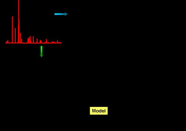
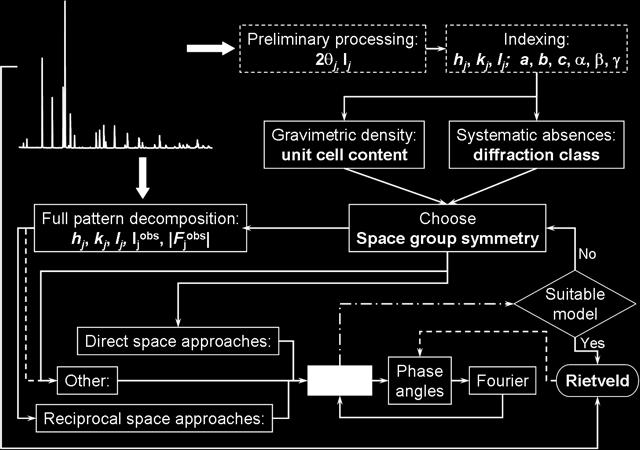
58 Going from Sample preparation and final structure by the powder method is a labyrinth
59 Going from Sample preparation and final structure by the powder method is a labyrinth
60 Going from Sample preparation and final structure by the powder method is a labyrinth See the nice site by Armel Le Bail who implemented the Monte Carlo methods
61
62
63 To which programs should we address (the list is not so numerous)??? We had a period of productivity in the past years
64

65 Von Dreele, R.B., Stephens, P.W., Smith, G.D., Blessing, R.H. The first protein crystal structure determined from high-resolution X-ray powder diffraction data: a variant of T3R3 human insulin-zinc complex produced by grinding. Acta Crystallogr., Sect.D v56 pp , 2000
66

67
68 Film Film is the oldest, and in some cases, still the best method (certainly the least expensive) for recording X-ray intensities optical density: light X-rays D D gamma log E light -- requiries many photons to transform one AgI grain (D log E) E X-rays -- one photon transforms many AgI grains (D E)
69 The relationships between a film intensity and ordinary powder diffraction pattern
70 Which Wavelength to Use in the home lab? Generally use Cu Å or Mo Å The longer the wavelength the farther apart the diffraction spots (lines) are in space. For large unit cells like macromolecules biologists should prefer Cu. Cu produces x-rays efficiently and the detectors have a higher efficiency in measuring them. Mo is not as absorbed as Cu. Best for heavy element problems. However metals have in general small unit cells.

71 Powder diffractometers working in the Bragg- Brentano (θ/2θ) geometry utilize a parafocussing geometry to increase intensity and angular resolution
72 Powder diffractometer operation proper choice of slits divergence slit small enough so that the beam does not spill off the sample, but large enough for adequate intensity (sometimes a θ-compensating slit is used) receiving slit large enough to receive entire Debye ring, but not too large to degrade resolution Soller slits improve resolution by decreasing vertical divergence errors axial divergence: flat specimen: specimen transparancy: sample displacement:
73 Reciprocity rules and atoms in the unit cell
74 Reciprocity rules and atoms in the unit cell The lattice simmetry determines the diffraction peaks sequence.
75 Reciprocity rules and atoms in the unit cell The lattice simmetry determines the diffraction peaks sequence. The elementary cell size determines peak densification in the diffraction space (according to reciprocity laws, small dimension determines large separation)
76 Reciprocity rules and atoms in the unit cell The lattice simmetry determines the diffraction peaks sequence. The elementary cell size determines peak densification in the diffraction space (according to reciprocity laws, small dimension determines large separation) Atom position within the unit cell affects the relative peak intensities
77 Reciprocity rules and atoms in the unit cell The lattice simmetry determines the diffraction peaks sequence. The elementary cell size determines peak densification in the diffraction space (according to reciprocity laws, small dimension determines large separation) Atom position within the unit cell affects the relative peak intensities Small crystallite size and large lattice strain affect the peak broadening
78 Sample Preparation X-ray diffraction: It is customary to remove material for analysis from the specimen and ground it to powder (powder is glued to (amorphous) glass slide) or use it as bulk specimen. Residual stress analysis: The bulk specimen is used as is. Use flat specimen, but avoid cutting and machining care must be taken in the specimen preparation in order not to introduce additional residual stresses. X-ray texture: Flat metallographic polished specimen is used. Bulk specimen for reflection pole figure, and thin (0.05 mm) specimen for transmission.
79 A polycrystalline sample should contain thousands of crystallites. Therefore, all possible diffraction peaks should be observed. 2θ 2θ 2θ For every set of planes, there will be a small percentage of crystallites that are properly oriented to diffract (the plane perpendicular bisects the incident and diffracted beams). Basic assumptions of powder diffraction are that for every set of planes there is an equal number of crystallites that will diffract and that there is a statistically relevant number of crystallites, not just one or two.
80 Instrumental Peak functions A large crystallite size, defect-free powder specimen will still produce diffraction peaks with a finite width The peak widths from the instrument peak profile are a convolution of: X-ray Source Profile Wavelength widths of Ka 1 and Ka 2 lines Size of the X-ray source Superposition of Ka 1 and Ka 2 peaks Goniometer Optics Divergence and Receiving Slit widths Imperfect focusing Beam size Penetration into the sample Intensity (a.u.) θ (deg.) Patterns collected from the same sample with different instruments and configurations
81 Animated processing of convolution Green curve y(t) is the convolution of the red curve x(t) and the blue curve h(t) The grey region indicates the product x(τ)h (t-τ); The convolution is thus the area of the grey region
82 You can use XRD to determine Phase Composition of a Sample Quantitative Phase Analysis: determine the relative amounts of phases in a mixture by referencing the relative peak intensities Unit cell lattice parameters and Bravais lattice symmetry Index peak positions Lattice parameters can vary as a function of, and therefore give you information about, alloying, doping, solid solutions, strains, etc. Residual Strain (macrostrain) Crystal Structure By Rietveld refinement of the entire diffraction pattern Epitaxy/Texture/Orientation Crystallite Size and Microstrain Indicated by peak broadening Other defects (stacking faults, etc.) can be measured by analysis of peak shapes and peak width