- Case study Groß Schönebeck -
|
|
|
- Aubrey Singleton
- 5 years ago
- Views:
Transcription

1 Enhanced Geothermal Systems (EGS) - Case study Groß Schönebeck - Günter Zimmermann, Guido Blöcher, Andreas Reinicke, Inga Moeck, Grzegorz Kwiatek, Wulf Brandt, Ali Saadat, Ernst Huenges Helmholtz Centre Potsdam GFZ German Research Centre for Geosciences
2 Reservoir systems Enhanced geothermal systems Natural permeability Suitable for reservoir enhancement*
3 Hydraulic stimulation technique: waterfracs (WF) water / low viscous gels: η = 1-10 mpa s reduction in costs compared or HPF without proppants or small proppant concentration: c = g/l long fractures: x f 250 m small width: w f ~ 1 mm application is limited to reservoirs with small permeability success is dependent on the self propping potential of the reservoir rock w f x f
 high viscous gels: η =")
 high proppant concentration:")


4 Hydraulic stimulation technique: hydraulic proppant fracs (HPF) high viscous gels: η = mpa s wide range of formations (permeabilities) high proppant concentration: c = g/l can be treated shorter fractures: x f = m good control of stimulation parameters big width: w f = 5-25 mm wellbore skin can be bypassed treatments are more expensive w f x f


5 What are Proppants?


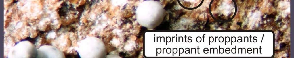
6 Optical Investigation of Rock-Proppant Interaction ti imprints of proppants proppant embedment abundant fines blocking pores at Bentheim ss fracture face fines blocking pores of proppant pack proppant crushing initiated at PP-contacts proppant embedment and fines production at the fracture face smaller amount of fines at Flechtingen ss fracture face amount of crushed HSP is small compared to ISP


7 Formation Damage Mechanisms in a Propped Fracture generation of a Fracture Face Skin - FFS filtration of frac fluids filter cake buildup relative perm. changes gas condensation sedimentation of fines proppant crushing reduction of fracture width gel residues and chemical precipitation proppant embedment due to mechanical interaction of rock and proppant Legarth et al. IJRM, 2005


8 Numerical Stress Modelling: Stress and Fracture Pattern σ diff = 50 MPa 3 A D B 2 E 1 3 C highly localized tensile stress near cleavage of proppants /di disintegration i i contacts / surfaces of quartz grains fines production and pore blocking at the fracture face explains the fines production and pore blocking at the fracture face explains the mechanically induced FFS
9 CT Scan of Proppant Embedment and Fines Production from A. Reinicke
10
11 Geological model Groß Schönebeck
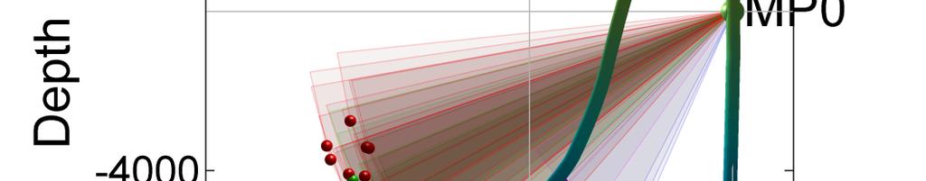
12 well paths and frac orientation Groß Schönebeck site
13 well paths and frac orientation Groß Schönebeck site
14 Doublet system Groß Schönebeck
15 Flow field of doublet system


16 History of Stimulation Treatments


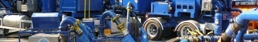
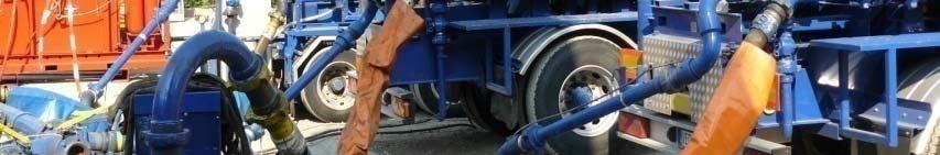


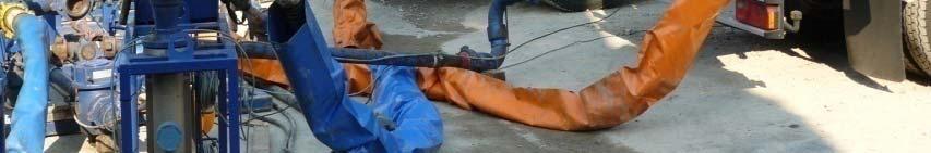


17 Frac Equipment
18 waterfrac treatment quartz sand added pres ssure [bar r] in] flowr rate [m³/m time pressure flowrate


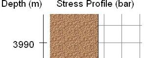
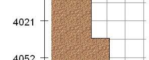
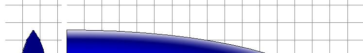
19 fracture propagation of waterfrac treatment sandstones conglomerates volcanics carboniferous hourly stages


20 microseismic monitoring moment magnitude Kwiatek et al., 2010


21 microseismic monitoring S H = 18 N Kwiatek et al., 2010

22 Kwiatek et al. Acta Geophysica 2010


23 end of waterfrac treatment
24 gel proppant treatment pre essure [ba ar] & prop conc [g/l] leakoff test step rate test frac flowra ate [m³/mi in] :00 10:00 11:00 12:00 13:00 14:00 15:00 time [hh:mm] pressure proppant flowrate


25 fracture propagation of gel-proppant treatment sandstones conglomerates volcanics


 35.00 30.63 26.25 21.")

26 Hydraulic fracturing MShale PFC2D Hofmann et al., Mw > 0.9 Fracpro Time (hr.) Zimmermann & Reinicke, 2010 Yoon et al., 2013
")


27 production test (CLT) mean flowrate = 30.2 m 3 /h duration = h production h shut-in
28 46 45 casing lift test (CLT) pressure release at well head (N 2 ) res servoir pr ressure [M MPa] res servoir tem mperature e [ C] time [s]
29 temperature logs during CLT tempe erature [ C] depth [m] temp1 down temp2 down temp1 up temp2 up
30 120 flowmeter logs during CLT gel/prop. frac 1. gel/prop. frac cum fl low [rev/s s] post perforations post perforations waterfrac + sand depth [m]
31 summary of treatments 500 m³ gel (YF140/145) + 4% KCl 113 t proppant (HSP 20/40coated/uncoated) P max = 495 bar Q max = 58 liter/sec 500 m³ gel (YF140/145) + 4% KCl 95 t proppant (HSP 20/40coated/uncoated) P max = 380 bar Q max = 66 liter/sec m³ water (ph5) 24 t sand P max = 586 bar Q max = 150 liter/sec.
32 acidizing and testing (CLT) 2009


33 acidizing and testing (CLT) 2009 coil tubing unit - reel diameter 2 - reel length 5000 m acid placement - 10 m³ of hydrochloric acid % concentration - between m MD - for 30 minutes casing lift test (CLT) - pressure gauge in 2350 m - duration 4 hours - total volume 140 m³
34 casing lift test gauge in 2350m [b bar] flowr rate [m³/h] :00 13:12 14:24 15:36 16:48 18:00 19:12 20:24 21:36 22:48 time gauge flowrate
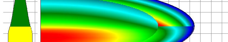
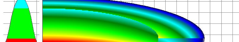
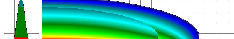
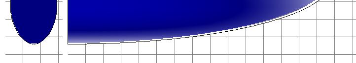
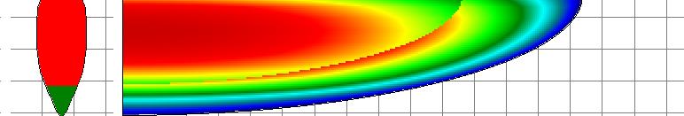
35 injection - production Propagation of cold water front (135 C) around the injection well (75m³/h; 70 C) over a period of 30 years (Blöcher et al., 2009)
36 interference with GrSk pressure in GrSk4 1, pressu ure [bar] pressure e [bar] pr ressure [bar] , :30 08:45 09:00 09:15 09:302009:45 10:00 10:15 10:30 10:45 11:00 time ,8 0,4 0,2 [m] gauge water level el in GrSk3 0 16:30 16:40 16:50 17:00 17: time time 1, ,9 1,85 1,8 1,75 1,7 gauge [m] gaug ge [m]
37 Communication 4/05 with 3/90 during waterfrac stimulation 2007 Injectionn of m³ in GrSk4
38 Pressure increase due to stimulation treatment Discrete flow paths influence significantly the flow and temperature field of the reservoir
39 interference with GrSk4
40 flow between doublet
41 conclusions - Stimulation methods should be laid out individually depending on: - Rock properties - Stratigraphic sequences - Structural geological settings, stress field - Shear potential and self propping effect - Application in Groß Schönebeck: - Waterfrac stimulation in volcanic rocks - 2 gel-proppant stimulations in sandstones - Acid stimulation in sandstones


42 This work was supported by the German Federal Ministry for the Environment, Nature Conservation and Nuclear Safety under grant BMU FKZ
43 Short description Experts in high temperature reservoirs -- in shallow and deep horizons in various geological situations in Europe -- provide basic, yet detailed knowledge on the utilization of European geothermal resources. From the contents Reservoir Definition Exploration Methods Drilling into Geothermal Reservoirs Enhancing Geothermal lreservoirs Geothermal Reservoir Simulation Energetic Use of EGS Reservoirs Economic Performance and Environmental Assessment