The designs, depending upon the methods used, may be classified as follows:
|
|
|
- Mark Warren
- 5 years ago
- Views:
Transcription
1 Definition Machine Design is the creation of new and better machines and improving the existing ones. A new or better machine is one which is more economical in the overall cost of production and operation. The process of design is a long and time consuming one. From the study of existing ideas, a new idea has to be conceived. The idea is then studied keeping in mind its commercial success and given shape and form in the form of drawings. In the preparation of these drawings, care must be taken of the availability of resources in money, in men and in materials required for the successful completion of the new idea into an actual reality. In designing a machine component, it is necessary to have a good knowledge of many subjects such as Mathematics, Engineering Mechanics, Strength of Materials, Theory of Machines, Workshop Processes and Engineering Drawing. Classifications of Machine Design The machine design may be classified as follows : 1. Adaptive design. In most cases, the designer s work is concerned with adaptation of existing designs. This type of design needs no special knowledge or skill and can be attempted by designers of ordinary technical training. The designer only makes minor alternation or modification in the existing designs of the product. 2. Development design. This type of design needs considerable scientific training and design ability in order to modify the existing designs into a new idea by adopting a new material or different method of manufacture. In this case, though the designer starts from the existing design, but the final product may differ quite markedly from the original product. 3. New design. This type of design needs lot of research, technical ability and creative thinking. Only those designers who have personal qualities of a sufficiently high order can take up the work of a new design. The designs, depending upon the methods used, may be classified as follows: (a) Rational design. This type of design depends upon mathematical formulae of principle of mechanics. 1
2 (b) Empirical design. This type of design depends upon empirical formulae based on the practice and past experience. (c) Industrial design. This type of design depends upon the production aspects to manufacture any machine component in the industry. (d) Optimum design. It is the best design for the given objective function under the specified constraints. It may be achieved by minimizing the undesirable effects. (e) System design. It is the design of any complex mechanical system like a motor car. (f) Element design. It is the design of any element of the mechanical system like piston, crankshaft, connecting rod, etc. (g) Computer aided design. This type of design depends upon the use of computer systems to assist in the creation, modification, analysis and optimization of a design. General Considerations in Machine Design Type of load and stresses caused by the load Motion of the parts or kinematics of the machine Selection of materials Form and size of the parts. Frictional resistance and lubrication Convenient and economical features Use of standard parts Safety of operation Workshop facilities Cost of construction Assembling General Procedure in Machine Design In designing a machine component, there is no rigid rule. The problem may be attempted in several ways. However, the general procedure to solve a design problem is as follows: Recognition of need. First of all, make a complete statement of the problem, indicating the need, aim or purpose for which the machine is to be designed. Synthesis (Mechanisms). Select the possible mechanism or group of mechanisms which will give the desired motion. 2
. Find the size of each member of the machine by considering the force acting on the member and the permissible stresses for the material used.")
3 Analysis of forces. Find the forces acting on each member of the machine and the energy transmitted by each member. Material selection. Select the material best suited for each member of the machine. Design of elements (Size and Stresses). Find the size of each member of the machine by considering the force acting on the member and the permissible stresses for the material used. It should be kept in mind that each member should not deflect or deform than the permissible limit. Modification. Modify the size of the member to agree with the past experience and judgment to facilitate manufacture. The modification may also be necessary by consideration of manufacturing to reduce overall cost. Detailed drawing. Draw the detailed drawing of each component and the assembly of the machine with complete specification for the manufacturing processes suggested. Production. The component, as per the drawing, is manufactured in the workshop. Engineering Materials 3
4 Choice of materials for a machine element depends very much on its properties, cost, availability and such other factors. It is therefore important to have some idea of the common engineering materials and their properties before learning the details of design procedure. Classification of Engineering Materials The engineering materials are mainly classified as: 1. Metals and their alloys, such as iron, steel, copper, aluminium, etc. 2. Non-metals, such as glass, rubber, plastic, etc. The metals may be further classified as: (a) Ferrous metals and (b) Non-ferrous metals. The *ferrous metals are those which have the iron as their main constituent, such as cast iron, wrought iron and steel. The non-ferrous metals are those which have a metal other than iron as their main constituent, such as copper, aluminium, brass, tin, zinc, etc. Selection of Materials for Engineering Purposes The selection of a proper material, for engineering purposes, is one of the most difficult problems for the designer. The best material is one which serves the desired objective at the minimum cost. The following factors should be considered while selecting the material: Availability of the materials, Suitability of the materials for the working conditions in service, and The cost of the materials. The stress in a plane which is at right angles to the line of action of the force. But it has been observed that at any point in a strained material, there are three planes, mutually perpendicular to each other which carry direct stresses only and no shear stress. It may be noted that out of these three direct stresses, one will be maximum and the other will be minimum. These perpendicular planes which have no shear stress are known as principal planes and the direct stresses along these planes are known as principal stresses. The planes on which the maximum shear stress act are known as planes of maximum shear. 4
5 A hollow shaft of 40 mm outer diameter and 25 mm inner diameter is subjected to a twisting moment of 120 N-m, simultaneously; it is subjected to an axial thrust of 10 kn and a bending moment of 80 N-m. Calculate the maximum compressive and shear stresses. Solution. Given: do = 40 mm; di = 25 mm; T = 120 N-m = N-mm; P = 10 kn = N; M = 80 N-m = N-mm We know that cross-sectional area of the shaft, Maximum compressive stress Maximum shear stress 5
6 A shaft, as shown in Fig. 5.17, is subjected to a bending load of 3 kn, pure torque of 1000 N-m and an axial pulling force of 15 kn. Calculate the stresses at A and B. Given: W = 3 kn = 3000 N; T = 1000 N-m = N-mm; P = 15 kn = N; d = 50 mm; x = 250 mm We know that cross-sectional area of the shaft Tensile stress due to axial pulling at points A and B, Bending moment at points A and B, This bending stress is tensile at point A and compressive at point B. Resultant tensile stress at point A, 6
7 Stresses at point A We know that maximum principal (or normal) stress at point A, Stresses at point B We know that maximum principal (or normal) stress at point B, Minimum principal (or normal) stress at point B, 7
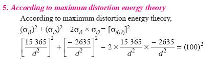
8 Theories of Failure under Static Load It has already been discussed in the previous chapter that strength of machine members is based upon the mechanical properties of the materials used. These properties are usually determined from simple tension or compression tests, therefore, predicting failure in members subjected to uniaxial stress is both simple and straight-forward. But the problem of predicting the failure stresses for members subjected to bi-axial or tri-axial stresses is much more complicated. In fact, the problem is so complicated that a large number of different theories have been formulated. The principal theories of failure for a member subjected to bi-axial stress are as follows: 1. Maximum principal (or normal) stress theory (also known as Rankine s theory). 2. Maximum shear stress theory (also known as Guest s or Tresca s theory). 3. Maximum principal (or normal) strain theory (also known as Saint Venant theory). 4. Maximum strain energy theory (also known as Haigh s theory). 5. Maximum distortion energy theory (also known as Hencky and Von Mises theory). Since ductile materials usually fail by yielding i.e. when permanent deformations occur in the material and brittle materials fail by fracture, therefore the limiting strength for these two classes of materials is normally measured by different mechanical properties. Problems The load on a bolt consists of an axial pull of 10 kn together with a transverse shear force of 5 kn. Find the diameter of bolt required according to 1. Maximum principal stress theory; 2. Maximum shear stress theory; 3. Maximum principal strain theory; 4. Maximum strain energy theory; and 5. Maximum distortion energy theory. Take permissible tensile stress at elastic limit = 100 MPa and poisson s ratio =
9 9
10 10
11 WELDING Introduction A welded joint is a permanent joint which is obtained by the fusion of the edges of the two parts to be joined together, with or without the application of pressure and a filler material. The heat required for the fusion of the material may be obtained by burning of gas (in case of gas welding) or by an electric arc (in case of electric arc welding). The latter method is extensively used because of greater speed of welding. Welding is extensively used in fabrication as an alternative method for casting or forging and as a replacement for bolted and riveted joints. It is also used as a repair medium e.g. to reunite metal at a crack, to build up a small part that has broken off such as gear tooth or to repair a worn surface such as a bearing surface. Advantages and Disadvantages of Welded Joints over Riveted Joints Following are the advantages and disadvantages of welded joints over riveted joints. Advantages The welded structures are usually lighter than riveted structures. This is due to the reason, that in welding, gussets or other connecting components are not used. The welded joints provide maximum efficiency (may be 100%) which is not possible in case of riveted joints. Alterations and additions can be easily made in the existing structures. In welded connections, the tension members are not weakened as in the case of riveted joints. The process of welding takes less time than the riveting. Disadvantages Since there is an uneven heating and cooling during fabrication, therefore the members may get distorted or additional stresses may develop. 11

12 It requires a highly skilled labour and supervision. Since no provision is kept for expansion and contraction in the frame, therefore there is a possibility of cracks developing in it. The inspection of welding work is more difficult than riveting work. Welding Processes The welding processes may be broadly classified into the following two groups: Welding processes that use heat alone e.g. fusion welding. Welding processes that use a combination of heat and pressure e.g. forge welding. Types of Welded Joints Following two types of welded joints are important from the subject point of view: Lap joint or fillet joint, and Butt joint. The other type of welded joints are corner joint; edge joint and T-joint as shown in Fig Below 12


13 The main considerations involved in the selection of weld type are: The shape of the welded component required, The thickness of the plates to be welded, and The direction of the forces applied. Problems Determine the length of the weld run for a plate of size 120 mm wide and 15 mm thick to be welded to another plate by means of 1. A single transverse weld; and 2. Double parallel fillet welds when the joint is subjected to variable loads. Given : Width = 120 mm ; Thickness = 15 mm In Fig , AB represents the single transverse weld and AC and BD represents double parallel fillet welds. 2. Length of the weld run for a double parallel fillet weld subjected to variable loads Let l 2 = Length of weld run for each parallel fillet, and s = Size of weld = Thickness of plate = 15 mm Assuming the tensile stress as 70 MPa or N/mm 2 and shear stress as 56 MPa or N/mm 2 for static loading. We know that the maximum load which the plate can carry is 13
14 A mm angle is to be welded to a steel plate by fillet welds as shown in Fig. If the angle is subjected to a static load of 200 kn, find the length of weld at the top and bottom. The allowable shear stress for static loading may be taken as 75 MPa. 14
15 A 50 mm diameter solid shaft is welded to a flat plate as shown in Fig. If the size of the weld is 15 mm, find the maximum normal and shear stress in the weld. Given : D = 50 mm ; s = 15 mm ; P = 10 kn = N ; e = 200 mm Let t = Throat thickness. The joint, as shown in Fig , is subjected to direct shear stress and the bending stress. We know that the throat area for a circular fillet weld, 15
16 A rectangular cross-section bar is welded to a support by means of fillet welds as shown in Fig. Determine the size of the welds, if the permissible shear stress in the weld is limited to 75 MPa. Given: P = 25 kn = N; τ max = 75 MPa = 75N/mm 2 ; l = 100 mm; b = 150 mm; e = 500 mm Let s = Size of the weld, and t = Throat thickness. The joint, as shown in Fig, is subjected to direct shear stress and the bending stress. We know that the throat area for a rectangular fillet weld, 16
17 17