Influence of rapid cooling rates for HIP on mechanical and corrosion properties of UNS S32205
|
|
|
- Thomasina Watson
- 5 years ago
- Views:
Transcription

 Hofer Werkstoff Marketing")
1 Influence of rapid cooling rates for HIP on mechanical and corrosion properties of UNS S32205 Arnulf Hörtnagl 1, Paul Gümpel 1, Michael Hamentgen², Beat Hofer³ Institute for Materials System Technology Thurgau at the University of Applied Sciences Konstanz (1) Powder Metallurgy, Saar Pulvermetall GmbH, Saarwellingen (2) Hofer Werkstoff Marketing Beratung (3)
2 Outline - Duplex stainless steel UNS S Effects of cooling rate - Influence of Process-Temperature - Experimental - Results -Conclusion and discussion
3 Duplex stainless steel UNS S32205
4 temperature Duplex stainless steel UNS S32205 according ASTM S32205 Composition in wt. pct. Carbon max Chromium Nickel Molybdenum Nitrogen Phosphorus max Manganese 2.00 max Sulfur max Silicon 1.00 max Iron Balance Temperature-Precipitation diagram of duplex stainless steel UNS S32205 influence of alloying constituents; Source: J. Charles; Duplex Stainless Steels 1991 time


5 Duplex stainless steel UNS S32205 Duplex stainless steel: - mixed microstructure - austenite / ferrite ratio usually 50/50 mix to 40/60 - twice the strength compared to austenitc stainless steels - improved resistance to localized corrosion - lean duplex: PREN > 25 - standard duplex: 22% Cr PREN > 32 - super duplex: PREN > 40 - hyper duplex: PREN > 48 Properties Density 7.80 g/cm³ Specific heat 460 J/Kg K Young s modulus 19.5 x 10 4 MPa Melting range C 0.2 % proof stress > 450 MPa Tensile strength MPa Hardness < 293 HB PREN
6 high N 2205 low N 2304 Temperature Duplex stainless steel UNS S32205 Chromium equivalent Cr eq = % Cr + 1.4% Mo C + 0.5% Nb + 1.5% Si + 2% Ti Cr eq = Alloy Cr eq /Ni eq Chemical Composition UNS DIN EN C Cr Ni Mo Mn N Si Cu S Vertical section of an Fe-Cr-Ni phase diagram at 60% Fe Source: J.C.Lippold, D.J. Kotecki; ISBN: Nickel equivalent Ni eq = % Ni + % Co + 0.5% Mn + 0.3% Cu + 30% N + 30% C Ni eq = 9.76 Cr eq / Ni eq = high N 2205 low N 2304
7 Norsok M-630 Standard / Duplex stainless steel UNS S32205 Aims - add value - reduce cost - lead time - increase safety - specify requirements What is NORSOK? Industry Initiative for the Competitive Standing of the Norwegian Offshore Sector Standards Norwegian Oil Industry Association Federation of Norwegian Engineering Industries M630 Material Data Sheets for Piping M650 Qualification of Manufacturers of Special Materials - Duplex Stainless Steels - High Alloyed Austentic Stainless Steels - Nickel Base Alloys (Castings) - Titanium and Alloys (Castings)
8 Norsok M-630 Standard / Duplex stainless steel UNS S32205 Requirements according Norsok M-630 Standard Tensile Testing Rp 0.2 R m > 450 MPa > 620 MPa A5 > 25 % Hardness maximum 28 HRC or 271 HB or 290 HV10 Impact Testing according ASTM A 370 at -46 C minimum 45 J / single 35 J Micrographic Examation according ASTM E % ferrite content
9 Effect of cooling rate
10 temperature Effect of cooling rate Cr 2 N χ-phase σ phase carbides 475 C -embrittlement time Time-Temperature-Transformation diagramm for various preciptitates appearing in duplex stainless steel UNS S32205; source: M. Sorg; NACE

11 temperature Effect of cooling rate Approx. Cooling rate 1000 C-700 C: 1.7 K/min over all: 0.2 K/min Cr 2 N χ-phase σ phase carbides χ-phase area min 475 C -embrittlement 475 C embrittlement more than 10 h TTT diagramm UNS S32205; scoure: M. Sorg; NACE time Approx % Austenite 32.5 % Ferrite 21.5 % intermetallic phases

12 temperature Effect of cooling rate Approx. Cooling rate 1000 C-700 C: 5 K/min over all: 0.25 K/min Cr 2 N χ-phase σ phase carbides χ-phase area min 475 C -embrittlement 475 C embrittlement more than 4 h TTT diagramm UNS S32205; scoure: M. Sorg; NACE time Approx % Austenite 41.0 % Ferrite 11.5 % intermetallic phases

13 temperature Effect of cooling rate Approx. Cooling rate 1000 C-700 C: 10 K/min over all: 0.35 K/min Cr 2 N χ-phase σ phase carbides χ-phase area min 475 C -embrittlement 475 C embrittlement more than 4 h TTT diagramm UNS S32205; scoure: M. Sorg; NACE time Approx % Austenite 43.5 % Ferrite 7.5 % intermetallic phases

14 temperature Effect of cooling rate Approx. Cooling rate 1000 C-700 C: 20 K/min over all: 0.5 K/min Cr 2 N χ-phase σ phase carbides χ-phase area min 475 C -embrittlement 475 C embrittlement approx. 1h TTT diagramm UNS S32205; scoure: M. Sorg; NACE time Approx % Austenite 46.5 % Ferrite 3.0 % intermetallic phases

15 temperature Effect of cooling rate Apporx. Cooling rate 1000 C-700 C: 50 K/min over all: 3.5 K/min Cr 2 N χ-phase σ phase carbides χ-phase area 5-10 min 475 C -embrittlement 475 C embrittlement min TTT diagramm UNS S32205; scoure: M. Sorg; NACE time Approx % Austenite 47.0 % Ferrite 1.5 % intermetallic phases

16 temperature Effect of cooling rate Approx. Cooling rate 1000 C-700 C: 60 K/min over all: K/min Cr 2 N χ-phase σ phase carbides χ-phase area 2-5 min 475 C -embrittlement 475 C embrittlement not reached TTT diagramm UNS S32205; sources: M. Sorg; NACE time Approx % Austenite 47.7 % Ferrite 0.2 % intermetallic phases
17 temperature Effect of cooling rate - increase the cooling rate Temperature profile - reduce the process temperature Cr 2 N χ-phase σ phase carbides 475 C -embrittlement TTT diagramm UNS S32205; scoure: M. Sorg; NACE time
18 Influence of Process Temperature


19 Influence of HIP-Temperature comparison of process temperatures 1200 C 1140 C 1100 C 1040 C without heat treatment approx. cooling rate critical temp.: 10 K/min over all: 1 2 K/min 1200 C : Ferrite 47% / Austenite 47.5 % / intermetallic phases 5.5 % 1140 C : Ferrite 47% / Austenite 51.5 % / intermetallic phases 1.5 % 1100 C : Ferrite 47.5% / Austenite 50.5 % / intermetallic phases 2 % 1040 C : Ferrite 47.5% / Austenite 50 % / intermetallic phases 2.5 %
20 Influence of HIP-Temperature comparison of process temperatures 1200 C 1140 C 1100 C 1040 C without heat treatment approx. cooling rate critical temp.: 10 K/min over all: 1 2 K/min CPT UNS S32205; sources: M. Sorg; NACE Impact energy UNS S32205; sources: M. Sorg; NACE


21 Resistance to crevice corrosion: Critical temperature for crevice formation in C Influence of HIP-Temperature comparison of process temperatures Corrosion Resistance according ASTM G C 1140 C 1100 C 1040 C test medium 6% FeCl 3 + 1% HCl testing period 24h Process Temperature
22 Experimental
")
23 Experimental Setup Goal experimental component evaluate benefits of fast cooling in industrial HIP facilities Process parameters HIP-Temperature 1140 C for 4 h realized cooling rate approx C / min approx kg one-half conventional heat treatment HIP-Samples one-half rapid cooling (HIP facility)
 modified test setup no heat treatment after HIP HIP with rapid cooling (approx.")
24 Experimental Setup Investigated wall thickness / edge distance 10 mm / 5 mm 70 mm / 35 mm 120 mm / 60 mm 175 mm / 88 mm sample conditions standard heat treatment with water quenching Jominy (ASTM A / DIN EN ISO 642) modified test setup no heat treatment after HIP HIP with rapid cooling (approx. 40 K/min)

25 Jominy (ASTM A / DIN EN ISO 642) modified test setup Goal develop and prove a new and cost efficient test method to illustrate the influence of cooling parameters and wall thickness for HIP products Jominy End Quench Test ASTM A 255 is used to measure hardenability of steels hardenability is a measure of the capacity of a steel to be hardened in depth when quenched form its austenitizing temperature (usually 800 C to 900 C) specimen cylinder 100mm in length and 25mm in diameter cooling rate decreases form the quenched end to the air cooled end: different cooling rates are generated wall thickness cannot depict by the usual experimental setup Image source: Nov. 2017


26 Jominy (ASTM A / DIN EN ISO 642) modified test setup Modification increasing sample length form 100 mm to 200 mm specimen isolation ceramic tube add an isolation add several thermocouples drape in an aluminum casting thermocouple aluminum casting water jet
27 Results


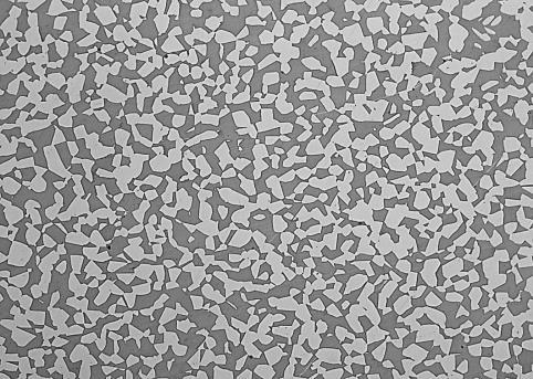
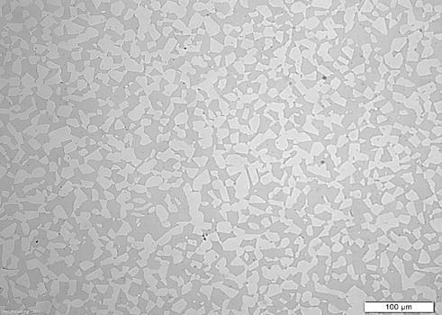
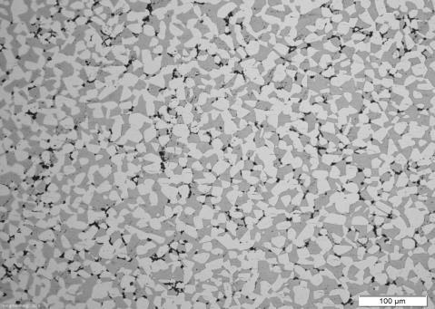
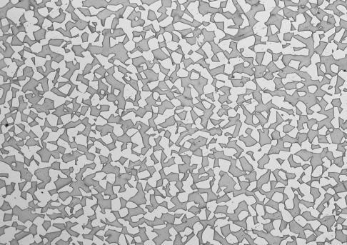


28 Microstructure edge distance modified Jominy test setup standard heat treatment water quenching HIP-Process with rapid cooling 170 mm 65 mm 5 mm
29 volume in % volume in % Austenite/Ferrite ratio standard heat treatment - water quenching modified Jominy test setup edge distance in mm edge distance in mm austenite ferrite precipitations austenite ferrite precipitations
30 volume in % volume in % Austenite/Ferrite ratio HIP with rapid cooling HIP without heat treatment edge distance in mm edge distance in mm austenite ferrite precipitations austenite ferrite precipitations
31 Corrosion resistance 70 Critical Pitting Temperature in C according ASTM G Standard heat treatment - water quenching modified Jominy test setup HIP-Process with rapid cooling HIP-Proces without heat treatment thickness / edge distance in mm


32 Impact energy notch impact energy according ASTM A370; conducted at - 46 C ductile fracture edge distance in mm Standard heat treatment - water quenching modified Jominy test setup HIP-Process with rapid cooling HIP-Proces without heat treatment brittle fracture 45 J / single 35 J minimum requirement for impact energy according to NORSOK M-630 Standard
33 brinell hardness HB yield strength MPa critical pitting tempreature ASTM G150 Mechanical properties Hardness Yield strength Corrosion edge distance in mm max. 271 HB according to NORSOK M-630 Standard edge distance mm min. 450 MPa according to NORSOK M-630 Standard edge distance mm
34 Conclusion & Discussion
35 Conclusion of results The results of corrosion measurements do not illustrate a significant effect of heat treatment or wall thickness / edge distance Demands and requirements of the NORSOK Standard will be achieved by fast cooling after HIP-Process only for thin-walled components (up to approx. 70mm) A small amount of intermetallic phases shows no significant reduction of corrosion resistance Notch impact energy is affected very strong by a small amount of intermetallic phases / precipitations The fracture surface of non heat treatment specimens shows brittle characteristics due to precipitations
36 temperature High cooling rate / Quenching UNS S2205 Computational example: UNS S kg specific heat capacity approx. 0.5 KJ/kg K Cr 2 N χ-phase σ phase carbides temperature difference specific heat 350 K (1000 C to 750 C) 175 MJ 475 C -embrittlement to prevent intermetallic phases 120 seconds (175 K/min) cooling power 1.45 MW 1.45 kw/kg TTT diagram UNS S32205; source: M. Sorg; NACE time
37 temperature in C High cooling rate / Quenching UNS N07718 INCONEL usually smaller components... lower critical temperature difference to cross... approx. 6 minutes to avoid intermetallic phases time in h TTT diagram IN718 source: A. Mostafa et. al; metals , 196;
38 temperature in C High cooling rate / Quenching UNS N07718 INCONEL 718 Computational example: UNS N07718 specific heat capacity approx kg KJ/kg K temperature difference specific heat 300 K (1050 C to 850 C) MJ to prevent intermetallic phases 360 seconds (50 K/min) cooling power 0.36 MW 0.36 kw/kg time in h TTT diagram IN718 source: A. Mostafa et. al; metals , 196;
39 Conclusion Process temperature is influencing Ferrite/Austenite ratio Grain size corrosion resistance Rapid cooling rates cannot replace conventional heat treatment to prevent intermetallic phases for thick-walled components made of UNS S32205 Help to accelerate the HIP-Process Parts can removed faster form your HIPunite Increasing the economic efficiency of the HIP-process / HIP-facility may be used for smaller parts or less sensitive materials

40 UNS S HIP-Temperature 1140 C / Groesbeck etching Thanks for your attention!