MICROSTRUCTURAL AND HARDNESS INVESTIGATIONS ON SIMULATED HEAT AFFECTED ZONE (HAZ) IN P91 CREEP RESISTING STEEL. Samsiah Sulaiman and Druce Dunne
|
|
|
- Piers Holt
- 5 years ago
- Views:
Transcription
1 MICROSTRUCTURAL AND HARDNESS INVESTIGATIONS ON SIMULATED HEAT AFFECTED ZONE (HAZ) IN P91 CREEP RESISTING STEEL Samsiah Sulaiman and Druce Dunne School of Mechanical, Materials and Mechatronic Engineering, Faculty of Engineering, University of Wollongong, Northfields Ave, Wollongong, NSW 2500, Australia ABSTRACT Thermal simulation has been used to investigate the structure and hardness of the subzones of the heat affected zone (HAZ) in welded P91 creep resisting steel. Microstructures corresponding to the sub-zones of the HAZ of actual welds were produced using a dilatometer. By simulation, the microstructure of each major subzone was reproduced in relatively large volumes compared with the corresponding subzone of the HAZ in an actual weldment. A simulated post-weld heat treatment (PWHT) was then imposed to gauge the effect on the structure and properties of the simulated sub-zones of the HAZ. Microstructural analysis and hardness testing confirmed that increasing peak temperature resulted in increases in the solution of alloy carbides, the mean austenite grain size and the hardness after cooling. Subsequent simulated PWHT served to re-precipitate carbide and to significantly reduce the hardness of the HAZ subzones. INTRODUCTION The relatively new 9-12 %Cr class of creep resisting ferritic steels has been developed for elevated temperature service for nuclear and fossil energy applications [1]. A steel containing 9% Cr and 1%Mo (P91) is being increasingly used for elevated temperature service in the power generating and processing industries, for components such as headers, superheaters and reheaters, because of its superior creep and oxidation resistance [2-4]. However, it has been found that the creep properties of the weld heat affected zone (HAZ) of these steels is inferior to those of both the base metal and weld metal. This is due to the problem of Type IV creep cracking in the intercritical HAZ (ICHAZ) region during high temperature service [5-6]. In the actual weld joint, the HAZ is only a few millimeters wide and the structures and properties of the sub-zones of the HAZ cannot be readily determined from an actual weld joint. Therefore, it is common to simulate the HAZ sub-zone microstructure by imposing a thermal cycle that corresponds to that experienced by the sub-zone during welding. Through simulation, a typical sub-zone microstructure can be reproduced in a relatively large volume compared to the corresponding sub-zone in the actual weld HAZ. Advantages of simulation include reduced scatter in mechanical test results because of the increased structural homogeneity. Therefore, studies of processes such 102
2 as creep crack initiation and growth are facilitated. However, effects that arise in actual welds such as the microstructural and property gradients and residual stresses cannot be taken into account by simulation. The purpose of the present work was to simulate the main sub-zones of the HAZ of P91 creep resisting steel using dilatometry, and to investigate their microstructures and hardnesses. A comparative analysis of the effect of simulated PWHT on microstructure and hardness was also undertaken. EXPERIMENTAL DETAILS Material The P91 creep resisting steel used in this investigation was supplied in a normalized (1040ºC-1080ºC) and tempered (750ºC-780ºC) condition. The structure was tempered martensite and average hardness was 224 HV10. The chemical composition of the P91 creep resisting steel investigated is given in Table 1. Table 1: The chemical composition (wt%) of the P91 steel used in the investigation Element C Mn Si S P Cr Ni Mo Element Nb Cu V N O Al Ti B <0.005 <0.01 <0.005 Simulation of HAZ microstructures A series of thermal simulations was carried out using a Theta high quench rate dilatometer to reproduce microstructures at selected peak temperatures during a weld thermal cycle. Specimens consisted of 10 mm long cylinders with 5 mm outer diameter (OD) and 3.5 mm inner diameter (ID). Specimens were heat treated at austenitising temperatures from 850ºC to 1400ºC. The heating rate was limited to 50 C/s, which is up to an order of magnitude lower than in actual welding. However, the cooling rate of 15 C/s and the holding time at the austenitising temperature of 1 second are typical of welding at a heat input of about 1.6 kj/mm. The simulated weld thermal cycle was followed by a simulated PWHT at a peak temperature of 760ºC and holding for 30 minutes, with heating and cooling rates at 0.5ºC/s. Heat treatment was carried out in a vacuum and helium gas was used for quenching to avoid any oxidation. Peak temperatures (T p ) from 850ºC to 1400ºC were used to represent the intercritical HAZ (ICHAZ), fine-grained HAZ (FGHAZ) and coarse-grained HAZ (CGHAZ) sub-zones. Microstructural examination and hardness The specimens were cross-sectioned, mounted, ground and polished according to standard metallographic procedures and etched with Vilella s reagent. Hardness testing was carried out using Vickers Hardness Testing machine with 10 kgf and 10 seconds indentation time. The hardness values are mean values of ten measurements. 103
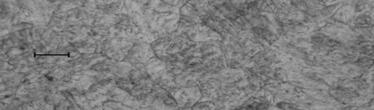
3 RESULTS AND DISCUSSION Microstructure and hardness Figure 1 shows the microstructure of the as supplied plate material, which consisted of tempered martensite. Carbides are resolvable in a ferrite matrix and prior austenite grain boundaries are evident. The hardness of the simulated ICHAZ structure is slightly lower than that of as supplied plate (Fig.2), indicating that the imposed thermal cycle over-tempered the structure. Simulated PWHT resulted in a further slight drop in hardness (Table 2 and Fig. 2). Figures 3(a) to 3(d) show microstructures of as simulated HAZ sub-zones and Figs. 3(a 1 ) to 3(d 1 ) present microstructures following superimposed simulated PWHT. The microstructure after austenitising at 850 C shows very little carbide dissolution, see Fig. 3(a), and is similar to the structure of the as supplied steel (Fig.1). This indicates that little if any re-austenitisation took place during the thermal cycle, even though the peak temperature (850 C) exceeds the A C1 range (800 C-830 C) specified by the steel manufacturer [7]. Since A C1 is heating rate dependent, the relatively high heating rate of 50 o C/s has probably elevated A C1 beyond the specified range. The microstructures formed with increasing T p from 900 C to 1200 C showed increased carbide dissolution, and progressively more transformation to austenite. The austenite grain size also increased, see to Figs. 3(c) to 2(d). The microstructure after austenitising at 1400 C showed total carbide dissolution in austenite and the coarsest austenite grain size, Fig.3 (d). The treatments with 850 C and 900 C peak temperatures lie between A C1 and A C3 and the microstructures are comparable to that of the intercritical HAZ of welded pipe as reported by Rui Wu et al. [8]. The microstructure after austenitising at 1200 C is consistent with the fine-grained HAZ, and the 1400 C treatment represents the coarsegrained HAZ. Both hardness and prior austenite grain size increased with increasing T p. However, the hardness of the simulated HAZ decreased following simulated PWHT, particularly for the higher peak temperatures, 1000 C to 1400 C, see Table 2 and Fig. 2. The hardnesses attained at 850 C, 900 C and 1000 C after PWHT were lower than that for as received P91 steel and were comparable to those measured in welds in the intercritical and grain refined sub-zones [8]. Similarly the hardness produced by 1400 C treatment, followed by simulated PWHT, is similar to that observed in the actual GCHAZ after PWHT [8]. 104
 Hardness (HV10) As simulated HAZ Simulated HAZ + PWHT 850 C 218 210 900 C 367 209 1000 C 396 218 1200 C 435 267 1400 C 441 280 Table.")
4 Figure 1: Micrograph of the as supplied plate material, which consisted of tempered martensite. The marker in 10μm. T p ( C) Hardness (HV10) As simulated HAZ Simulated HAZ + PWHT 850 C C C C C Table.2: Mean hardness values as a function of the peak thermal cycle temperature, T p Hardness, HV As simulated HAZ 100 Simulated HAZ + PWHT Peak Temperature, Tp, C Figure 2: Hardness versus peak thermal cycle temperature T p. The broken horizontal line indicates the average hardness of the as supplied plate steel. 105


")


5 a T p = 850 C a 1 T p = 850 C b T p = 1000 C b 1 T p = 1000 C c T p = 1200 C c 1 T p = 1200 C d T p = 1400 C d 1 T p = 1400 C Figure 3: (a to d) show microstructures of the simulated HAZ sub-zones corresponding to the indicated peak thermal cycle temperature; (a 1 to d 1 ) show the corresponding microstructures after simulated PWHT. The marker in 10μm. 106
6 CONCLUSIONS Thermal simulation by dilatometry has been used to study the structure and hardness of the sub-zones of the HAZ in P91 creep resisting steel. Simulated weld thermal cycling to peak temperatures in the range 850 C to 1400 C was used to represent the IC, FG and CG sub-zones of the HAZ. 1) Treatments to peak temperatures of 850 C to 900 C showed partial carbide dissolution and after simulated PWHT the microstructures and hardness were comparable to those of the ICHAZ of actual welds. Treatment at 1400 C showed full alloy carbide solution and, after simulated PWHT, the microstructure and hardness were similar to those of the actual weld CGHAZ. 2) The hardness after weld thermal cycle simulation to peak temperatures > 850 C increased because of increasing carbide dissolution in the austenite and subsequent formation of more highly alloyed martensite. Simulated thermal cycling to T p temperatures in the range 850 C to 1400 C produced hardnesses in the range HV10, but subsequent simulated PWHT normalized the hardness across the sub-zones, reducing it to the range 210 to 280 HV10. 3) The investigation established that weld thermal cycle simulation using a dilatometer closely reproduces the structures and properties typical of the actual HAZ sub-zones in welded P91 steel. ACKNOWLEDGEMENTS The assistance of Dr John Francis and Dr Voytek Mazur, CSIRO MIT, Adelaide, is gratefully acknowledged. The financial support of Samsiah Sulaiman by the Malaysian Government through provision of a PhD scholarship is also acknowledged with gratitude. REFERENCES [1] Cunningham, G.W., Patriarca, P. and Hoffman, E.E., (1981), Proceedings of an ASM Conference on fabrication, Properties and application of Ferritic Steels for High Temperature Applications, 3-6. [2] Bendic, W., Niederhoff, K., Wellnitz, G. Zschau, M. and Cerjak, H., et al., (1992), Proc. 3 rd Int. Conf. on Trends in Welding Science and Technology, ASM, [3] Cerjak, H., Letofsky, E., and Schuster, F., (1995), Proc.4 th. Int. Conf.on Trends in Welding Research, ASM International, [4] Okabayashi, H. and Kume, R., (1988), Trans. Jpn.Weld. Soc., [5] Ellis, F.V. and Viswanathan, R., (1998), Integrity of high temperature welds, London: Prof. Publishing Ltd, 125 [6] Bell, K., (1997), Report 597/1, The Welding Institute. [7] Vallourec & Mannesmann Tubes, The TP1/P91 Book, (1999), [8] Wu, R., Sandstrom, R. and Seitisleam, F., (2004), Journal of Engineering Materials and Technology, 126,