Solution Partner. Leak - Proof Flow & Control. W e. s u p p o r t. t h e. i n n o v a t i o n s. o f. c u s t o m e r s
|
|
|
- Camron Hensley
- 5 years ago
- Views:
Transcription

1 W e. s u p p o r t. t h e i n n o v a t i o n s. o f. c u s t o m e r s Leak - Proof Flow & Control The Best Partner for Value Creation Solution Partner

2 Tube Fittings have been designed specifically for the many demanding applications such as chemical, petroleum, power generating, pulp and paper, and various types of manufacturing industries. They provide a highly reliable, leak proof and torque free seal on all tubing connections. Tube Fittings are commonly used on instrumentation, process and control systems where high quality tube fittings are required.


3 Certificate List API Spec Q1 Registered API ISO/TS REGISTERED API Spec.Q1 API Monogram ABS Lloyd;s DNV GL BV KR NK
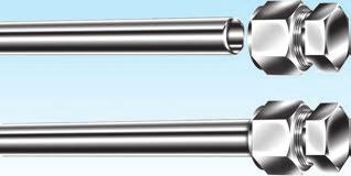
4 INTRODUCTION OF S-LOK TUBE FITTING S-LOK tube fittings are manufactured under very strict quality control to assure maximum reliable performance. S-LOK tube fittings require no special tools assembly. Connections can be quickly and easily made by simple insertion and tightening the nuts. S-LOK tube fitting has been specifically designed for use on instrumentation, process and control systems and equipment employed in chemical, petroleum, power generating and pulp and paper plants. S-LOK tube fittings could also be used in extensive applications of other fields where very high quality tube fittings are required. CONSTRUCTION OF S-LOK TUBE FITTINGS S-LOK tube fittings are composed of four precision parts; body,nut,front ferrule and back ferrule. By screwing the nut onto the body, the nut is tightened against the tapered area of the body, and its edge is compressed tightly against the tube by curling inward. The back ferrule is also located between the body and nut. As the front ferrule rolls, the back ferrule rolls up and bites into the tube resulting in the connection of tube and the fitting as well as a non-leakage effect. The twin ferrule design achieves the leak proof sealing by assembly motion being transmitted axially through the tubing. This results in no radial movement of the tubing upon assembly. Therefore, the tube is not stressed and the mechanical integrity is maintained. This is the result of close monitoring of tolerance control in machining, and surface smoothness and hardness of each and every part of S-LOK tube fittings. Through this swaging action, S-LOK tube fittings are mechanically integrated with the tube connected. S-LOK Fractional Tube End Dimensions Unit:mm S-LOK Metric Tube End Dimensions Unit:mm Size No. Tube O.D S-LOK Thread A B d Hex. Size No. Tube O.D S-LOK Thread A B d Hex. 2 1/8 5/16-20UN M 3mm 5/16-20UN /16 3/8-20UN M 4mm 3/8-20UN M 6mm 7/16-20UNF /4 7/16-20UNF M 8mm 1/2-20UNF /16 1/2-20UNF M 10mm 5/8-20UN /8 1/2 9/16-20UN 3/4-20UNEF M 15M 12mm 15mm 3/4-20UNEF 7/8-20UNEF /8 7/8-20UNEF M 16mm 7/8-20UNEF M 18mm 1-20UNEF /4 1-20UNEF M 20mm 1-1/8-20UN /8 1-1/8-20UN M 22mm 1-1/8-20UN /16-20UN M 25mm 1-5/16-20UN FITTING MATERIALS S-LOK tube fittings are made of 316 stainless steel (S316), brass and alloy steel such as Monel or others. SUITABLE TUBING MATERIALS S-LOK tube fittings can be used with the following tube specifications. Stainless steel tube; a. TP304 and TP316 of ASTM A269 or A213, or equivalent. b. SUS304TP and SUS316TP of JIS G3459 or equivalent. c. The wall thickness selection should be based on the operation pressure, temperature and shock conditions. Fully annealed tubing is recommended. Stainless steel tubing with the hardness of Rockwell B80 or less should be used. d. Specific recommendation-see Table 1.(page 5) Typical Raw Material List Fitting Meterial Bar Stock Forging Tubing Stainless Steel Type 316 Brass Carbon Steel Alloy 400 ASTM A479 ASTM A276 JIS G4303 ASTM B16 Alloy 360 ASTM B453 Alloy 345 JIS H3250 Alloy C3604 JIS G4051 S20C-S48C ASTM B164 ASTM A182 F316 JIS G3214 ASTM B124 Alloy 377 JIS H3250 Alloy C3771 JIS G4051 S20C-S48C ASTM B164 ASTM A269 ASTM A213 ASTM A249 ASTM B68 ASTM B75 ASM B88 DIN 1786 ASTM A161 ASTM A179 DIN 2391 ASTM B165 4
5 Tubing Suitable tube selection is essential in performance of tubing system. For safe, reliable and leak-free seals tubing should be considered as a fitting component. S-LOK tube fittings perform best when good quality tubing is used. When selecting tubing material including size and wall thickness, customer must consider pressure, flow, temperature, environment and compatibility of system. - General Rules. 1. For leak-free sealing, the tubing surface is very important. The tubing must have a good surface condition with free of scratches, draw mark, flat spots or dirt. 2. In case of welded tubing, it should not have a visible poor bead on its surface. 3. Tubing and fitting material is essential for the thermal compatibility and corrosion resistance. The material should be compatible with the processing fluid, the temperature and the environment. 4. Tubing must be softer than fitting material. When tubing and fittings are made of the same material, the metal tubing must be fully annealed. 5. Tubing hardness must be selected according to the information in the table 2 to Do not select a too thin or too thick wall. A too thin wall may collapse, and a too thick wall may not properly be deformed by the ferrule action. Selecting the wall s thickness should be based on the applicable pressure, temperature, shock and vibration. - Consider the following in selecting tube. 1. Quality of the tubing material and manufacturing method. 2. Hardness of tube. 3. Surface treatment of tube. 4. O.D and tolerance. 5. Wall thickness and tolerance. 6. Concentricity of tube. 7. Ovality. (Shape) Tubing Temperature Ranges The maximum and minimum operating temperatures for various tubing material. Tubing Material Stainless Steel 316 Carbon Steel Copper Alloy 400 Alloy C276 Alloy 600 Titanium PTFE Elastomer seal material Temperature Range -321 to 1200 (-196 to 649 ) -65 to 799 (-53 to 426 ) -40 to 400 (-40 to 205 ) -324 to 800 (-198 to 427 ) -320 to 1000 (-195 to 537 ) -205 to 1200 (-130 to 648 ) -320 to 600 (-195 to 315 ) 0 to 150 (-17 to 65 ) Allowable Working Temperature When Elastomer seal is used in the fitting,care must be taken for allowable working temperature. Seeworking temperature below. Working Temperature Temperature De-rating Factors The allowable working pressure is determined by various temperatures. To determine the working pressure at the specific temperatures, multiply the working pressure at ambient temperature shown in table 2~4 by the factor shown in table1. Table 1. Temperature De-rating Factors Temp. ( ) (37) (93) (148) (204) (206) (315) (370) (426) (480) (537) (649) Stainless Steel ASTM A C.Steel ASTM A Copper ASTM B Alloy NBR (e. g. Perbunan ) FKM (e. g. Viton ) PTFE (e. g. Teflon ) -40 to 110 (-40 to 230 ) -28 to 204 (-20 to 400 ) -60 to 204 (-76 to 464 ) Example : Tube S316 3/8 O.D. x at psi x 0.82 = 2.706psi Therefore 2.706psi is the maximum allowable working pressure of S316 3/8 O.D x wall tubing. 5
6 Stainless steel Tubing : Fully annealed 304 or 316 high quality seamless steel tube to ASTM A269 or equivalent. Hardness : HRB90 or less Table 2. Stainless steel Tubing Stainless Steel Fractional Tubing Tube O.D (inches) Tube Wall Thickness in Inches /16 1/8 3/16 1/4 5/16 3/8 5,600 6,800 8,100 9,400 12,000 1/2 5/8 3/4 7/8 For gas service, applying tube wall thickness should only be selected from the outside of the shaded boundary 1 1 1/4 1 1/2 2 8,500 5,400 4,000 10,900 7,000 5,100 4,000 3,300 2,600 10,200 7,500 5,800 4,800 3,700 2,900 2,400 2,000 10,200 8,000 6,500 5,100 4,000 3,300 2,800 2,400 6,700 5,200 4,200 3,600 3,100 2,400 6,000 4,900 4,200 3,600 2,800 2,300 5,800 4,800 4,200 3,300 2,700 2,000 4,700 3,600 3,000 2,200 4,100 3,400 2,500 4,900 4,000 2,900 4,900 3,600 Stainless Steel Metric Tubing Tube O.D (mm) (0.028) (0.035) (0.049) (0.065) 10,800 7,900 5,000 13,800 10,100 6,500 4,700 3,700 3,000 15,300 11,500 7,400 5,800 4,200 3,400 2,500 14,400 9,400 6,800 5,300 4,400 3,200 11,500 8,400 6,500 5,300 3,900 12,700 9,300 7,300 5,900 4,300 Tube Wall Thickness in Inches (0.083) (0.095) 6,600 5,300 7,000 5, For gas service, 2,800 3,400 3,800 4,700 5,000 5,800 6,000 6, applying tube wall 2,500 3,000 3,400 4,200 4,400 5,100 5,300 6, thickness should only 2,300 2,800 3,000 3,800 4,000 4,600 4,800 5, be selected from the 2,000 2,400 2,700 3,300 3,500 4,000 4,200 4,700 5,100 5, outside of the shaded boundary 2,300-2,900-3,400 3,900 4,400 Working pressures are based on allowable stress value of 20,000psi (137,800kPa=1,378bar)as specified in ASME B within the temperature range of -29 to 37 (-20 to 100 ). Safety Factor=3.75:1, considering ultimate tensile strength 75,000psi (516,700kPa=5,167bar) Pressure calculations are based on Maximum O.D. and minimum wall thickness, and no allowance is made for corrosion and erosion. e.g. ASTM A269 1/2 O.D x OD tolerance 0.005,W.T. 10%. Calculations are based on OD x W.T. To determine bar, Multiply psig by To determine kpa, multiply psig To convert bar to psig, multiply bar by For working pressure of ASME B31.1, multiply the above value by , (0.109) 6,800 Welded stainless steel Tubing Based on ASME B for weld integrity, a de-rating factor must be applied to welded tubing. For double butt seam tubing, multiply by 0.85 For single butt seam tubing, multiply by (0.120)
7 Copper tubing : High quality soft annealed seamless copper tube to ASTM B-75 or equivalent. Hardness : Rockwell 15T 60 or less Table 3. Copper Tubing Copper Fractional Tubing TubeO.D. (inches) Tube Wall Thickness in Inches /16 1,700 3,800 5,400 6,000 1/8 3/16 2,700 1,800 3,400 2,300 3,400 1/4 1,300 1,600 2,500 3,500 5/16 1,300 1,900 2,700 3/8 1,000 1,600 2,200 1/2 For gas service, applying 800 1,100 1,600 2,200 5/8 tube wall thickness should only 900 1,200 1,600 1,900 3/4 be selected from the outside of 700 1,000 1,300 1,500 1,800 7/8 the shaded boundary ,100 1,300 1, ,100 1,300 1,500 Copper Metric Tubing Tube O.D. (mm) 0.71 (0.028) 0.89 (0.035) (0.049) Tube Wall Thickness in Millimeters(inches) (0.065) (0.083) 2.41 (0.095) (0.109) (0.120) 3 3,465 4,400 4, ,520 1,6110 3,230 2,070 3,670 2,350 4,610 3,020 3,670 4, ,510 1,710 2,790 2,680 2, ,190 1,350 1,710 2,090 2, ,100 1,410 1,710 1,900 2,350 2, For gas service, 810 1,030 1,260 1,390 1,710 1,810 2,100 2, applying tube wall thickness 915 1,100 1,220 1,510 1,600 1,840 1,930 2, should onlybe selected ,090 1,350 1,420 1,650 1,710 1, from the outside of the ,200 1,290 1,480 1,550 1, shaded boundary ,060 1,120 1,290 1,350 1,490 1,640 1,670 Working pressures are based on allowable stress value of 6000psi(413bar=41,300kPa)as specified in ASME B within the temperature range of -29 to 37 ( to 100 ). Safety Factor=5:1, considering ultimate tensile strength 30,000psi (2067bar=206,700kPa) Pressure calculations are based on Maximum O.D. and minimum wall thickness, and no allowance is made for corrosion and erosion. For working pressure of ASME B31.1, multiply the above value by
8 Alloy 400 Tubing Fully annealed seamless Alloy 400 tubing to ASTM B165 or equivalent. Hardness : HRB75 or less Table 4. For seamless Alloy400 Tubing For seamless Monel 400 Fractional Tubing Tube O.D. (inches) 1/8 1/4 3/8 1/2 3/4 1 Tube Wall Thickness in Inches ,900 10,100 3,700 4,800 7,000 9,500 3,100 4,400 6,100 2,300 3,200 4,400 2,200 3,000 4,000 4,600 2,200 2,900 3,400 3,900 4,300 Working pressures are based on allowable stress value of 20,000psi (137,800kPa=1,378bar)as specified in ASME B within the temperature range of -29 to 37 (-20 to 100 ). Safety factor=3.75:1, considering ultimate tensile strength 70,000psi (482,300kPa=4,823bar) Pressure calculations are based on maximum O.D. and minimum wall thickness, and no allowance is made for corrosion and erosion. For working pressure of ASME B31.1, multiply the above value by 0.94 Special Alloy Tubing When special alloy tubing is selected, we recommend: Fully annealed seamless (or welded and cold-drawn, where permitted) alloy tubing to the ASTM specification as shown below. Tubing should be free of scratches for bending or flaring. S-LOK material Designator C276 A600 Ti Tube Material Alloy C276 Alloy 600 Titanium-Grade2 ASTM Number B622 B167 B338 Type Seamless Seamless Seamless or Welded Tubing Maximum hardness HRB 100 HRB 92 - Pressure Rating Equivalents: 1) 1bar = 100kPa = 14.51psi 2)1kPa = 0.01bar = psi 3) 1psi = 0.069bar = 6.89kPa 4)1 = 0.98bar = 14.22psi Tubing for Gas application S-LOK tube fittings are designed for a wide range of leak-free application including gas leak proof and vacuum service. Gases can escape even the most minute leakpath due to their small molecules. Tube must therefore be carefully handled not to get scratched. Use heavier wall tubing for gas service. Heavy wall tubing resists ferrule action by coining out minor defects of the tube surface, and thin wall tubes may collapse with little resistance to ferrule action. For gas service, use the tubing of the un-shadowed section in table 2-4 Cryogenic Service S-LOK fittings in 316 stainless steel provide highly reliable performance from cryogenic temperatures to high temperature levels. 316 stainless steel temperature range : -321 to 1200 (-196 to 649 ) Cryogenic temperature are considered to be temperatures below : -100 (-73 ) 8

9 Pipe Thread Many S-LOK tube fittings have a male or female pipe end. These ends occasionally have a lower pressure rating than the pressure rating of the tube fitting end so consider both of the ratings. Table5. Pipe End Pressure Rating ISO/NPT Stainless Steel 316 Brass Carbon Steel Size Pipe Male Female Male Female Male Female Designator Size pisg bar pisg bar pisg bar pisg pisg pisg bar pisg pisg 1 1/16 11, , , , , , /8 10, , , , , , /4 8, , , , , , /8 7, , , , , , /2 7, , , , , , /4 7, , , , , , , , , , , , /4 6, , , , , , /2 5, , , , , , , , , , , , The ratings shown above are based on ASME B Female pipe ends have lower ratings than male pipe in a given size due to the inner and outer diameters of female threads being larger than those of male pipe ends. The ratings shown above are reference only. Pipe Thread Sealant Pipe thread sealant is essential to ensure leak-free seal. Since the PTFE tape is commonly used, we provide information of recommended tape width, as well as the numbers of thread to be wrapped. The PTFE tape fills the voids between threads and prevents galling on pipe threads. The sealant usually contains a lubricant. Table 6. Nominal Pipe Size Recommended Tape Width 1/8 1/8-1/4 1/4 1/4 3/8 1/4 1/2 1/4-1/2 3/4 1/4-1/2 1 1/4-1/2 ASME B NPT Effective Thread Length (External) L Approx.# of Thread 7 7-1/4 7-1/3 7-1/2 7-2/3 8 Note 1.Wrap PTFE tape clockwise from first thread. Do not overhang the first thread, as the tape may get into the fluid system. 2.PTFE tape has a temperature limit of 230 (450 ) Unit : inches Note The information shown in table 1-6 are not for design purpose, but for reference only. The accuracy of information is not the liability of our company. 9
. Mark the nut at the 6 o clock position before placing the spanner.")


10 Tube Fitting Instruction Manual Installation Instruction Gageability Fully insert the tube into the fitting and against the shoulder; tight the nut by finger-tightening. (Caution : The tube may be elliptical or have burrs; foreign material on the surface and/or inside of the tube fitting). Mark the nut at the 6 o clock position before placing the spanner While holding the fitting body steady, tight the nut with the spanner by turning one and one-quarter (1 1/4) clockwise. Make sure that the spanner s starting point at 6 o clock is being positioned at 9 o clock after tightening 1 1/4 clockwise. Tighten the nut only 3/4 turn to the 3 o'clock position for 1/16, 1/8 and 3/16 inch (2mm, 3mm and 4mm) size tube fittings. When it was tightened 1 1/4 turn clockwise, the tube fitting has been designed to be endurable even from the bursting pressure of the tube, therefore insufficient tightening against the regulation may cause the leakage and bursting while over-tightening makes the reassembly difficult due to deformity Gap Inspection Gage assures the installer or the inspector that the instrument has been sufficiently tightened during the first installation inspection. Place Gap Inspection Gage at the gap between the nut and body. When the gage does not fit into the gap, it means that the fitting is sufficiently tightened. When the gage fits into the gap, it means that it needs to be tightened more. Reassembly Instruction S-LOK products can be disassembled and reassembled numerously. For reassembly, insert the tube with ferrules into the fitting until the front ferrule seats against the fitting body to avoid any damage from foreign objects at the disassembled area. After hand-tightening the nut while holding the fitting s body steady, tight the nut with a spanner to the previously pulled-up position. At this point, you would feel a significant increase in resistance. Then tight the nut slightly
11 Proper Tube Handling Good handling practices can greatly save the good surface finish of the supplied tube. Tubing should never be dragged out of a tubing rack. Tubing should never be dragged across cement, asphalt, gravel or any other rough surface. Tubing cutter wheel and hacksaw blade should always be sharp. Try not to take deep cuts with each turn of the cutter or stroke of the saw. Tube end should always be deburred. Tubing should be stored to avoid collection of dirt and contamination. If possible, tubing ends should be plugged, so any foreign materials will not fall inside. Tube bending For sealing installation in case of bended tubing being near S-LOK fittings, there should be enough lineal distance from bending point to the fittings. When tube bend is too close to the fitting, the deformed section of the bend may enter the fitting, and it may result in leaking. Also, the bending radius should not be too short of bending radius may affect the working pressure and may cause insufficient flow. Minimum bending radius is usually recommended by the tube bending manufacturer. Tubing Straight Lengh T : Tube O.D. R : Radius Follow the bented tube vendor s recommendation. L : Straight tubing length is required from the beginning of the bend to the tubing end. See table below. Length of straight section of Fractional tubing Tube O.D Straight Lengh L1 L2 1/16 2/1 13/32 1/8 23/32 19/32 3/16 3/4 5/8 1/4 13/16 11/16 5/16 7/8 23/32 3/8 15/16 3/4 1/2 13/16 31/32 5/8 1-1/4 1-1/32 3/4 1-1/4 1-1/32 7/8 1-5/16 1-1/ /2 1-9/32 1-1/ /16 1-1/2 1-13/32 2-7/ /4 3-1/32 Unit:Inch Length of straight section of Metric tubing Tube O.D Straight Lengh L L Unit:mm Note L1=Recommended length of straight section of tubing required L2=Absolute minimum length of straight section of tubing required 11
12 ORDERING INFORMATION The symbols in the part number column on each page represent the shape and size of individual fittings. Example 1 : Tube to Pipe ends Example 2 : Tube to Tube ends S-LOK Tube Fitting (Double Ferrule) Name of Fitting (Male Connector) Tube O.D Designations (4mm O.D) S M C - 4 M - 4 R - S 6 S T - 8 M - S 6 Material Designator Thread symbol R(PT) Pipe Thread Designations(1/4 ) S-LOK Tube Fitting (Double Ferrule) Name of Fitting (Union Tee) Material Designator Tube O.D Designations (8mm O.D) Example 3 : Tee& Cross Tees are described by first the run (1 and 2) and next the branch(3) Cross are described by first the run (1 and 2) and next the branch (3 and 4) Tube O.D. Designator 3 Inch O.D Identifier Metric O.D Identifier 1/16 1 2mm 2M 1/8 2 3mm 3M 3/16 3 4mm 4M 1/4 4 6mm 6M 5/16 5 8mm 8M 3/8 6 10mm 10M 1/2 8 12mm 12M 5/ mm 16M 3/ mm 20M 7/ mm 22M mm 25M 1-1/ mm 28M 1-1/ mm 32M mm 38M Pipe Thread Size Designator Nom. Size 1/8 1/4 3/8 1/2 3/ /4 1-1/2 2 3 Fitting Material Designator Material S316 S316L SS304 Carbon Steel Brass Alloy400 Identifier Identifier S6 S6L S4 CS BS A400 Pipe Thread Symbol Type Symbol Specification R Taper Threads ISO 7/1, BS21(BSPT), JIS B 0203(PT), DIN2999 N ANSI B (NPT) G ISO228/1, BS 2779(BSPP), JIS B0202(PF) Parallel Threads U American Standard Unified Screw Threads 12
13 , , , Welding Bulkhead Union 55 25, , , , ,
14 14

15 15
16 16
17 17
18 18

19 19
20 20
21 21
22 22 S-LOK theremocouple connector has no shoulder nor sizing angle inside the fitting; the features enable thermocoupler to go through the fitting s thread end.
23 23
24 ISO 24
25 ISO The ISO 7/1 is a tapered thread that is sealing threads working by interference fit. This still requires thread sealant for pressure-tight seal by filling the voids between threads, and further, this prevents galling on piping threads. The sealant usually contains a lubricant. S-Lok Pipe Thread Designator 25
26 26
27 27
28 28

29 29
30 30

31 31
32 32
33 33
34 34
35 35
36 36
37 37
38 38
39 39
40 40
41 41

42 42


43 43

44 44
45 Female Adapter SAG Connects fractional S-LOK port to male ISO tapered thread Part No. SAG-4-2G SAG-4-4G SAG-6-6G SAG-8-8G Tube O.D. D in 1/4 1/4 3/8 1/2 mm T G(PF) 1/8 1/4 3/8 1/2 E Min E Width across flat h in mm 9/ / / / L Connects metric S-LOK port to male ISO tapered thread Part No. Tube O.D. D T G(PT) E Min. Width across flat h SAG-6M-2G SAG-6M-4G SAG-6M-6G SAG-6M-8G SAG-8M-4G SAG-8M-6G SAG-8M-8G SAG-10M-4G 6M 6M 6M 6M 8M 8M 8M 10M 1/8 1/4 3/8 1/2 1/4 3/8 1/2 1/ SAG-10M-6G 10M 3/ SAG-10M-8G 10M 1/ SAG-12M-4G 12M 1/ SAG-12M-6G 12M 3/ SAG-12M-8G 12M 1/ SAG-15M-8G 15M 1/ SAG-16M-8G 16M 1/ SAG-18M-8G 18M 1/ SAG-22M-8G 22M 1/ SAG-25M-8G 25M 1/ E1 L 45
46 46
47
48 LOK LOK 48

49 49

50 50
51 LOK 51
52 52
53 LOK LOK LOK LOK 53
54 54
55 55 Connects fractional Tubes Connects Metric Tubes Part No. SBUW-1 SBUW-2 SBUW-3 SBUW-4 SBUW-5 SBUW-6 SBUW-8 SBUW-10 SBUW-12 SBUW-14 SBUW-16 SBUW-20 SBUW-32 SBUW-24 Tube O.D. D in mm 1/16 1/8 3/16 1/ / / / / / / / / min d H in 5/16 7/16 7/16 1/2 9/16 5/8 13/16 15/16 11/16 13/16 13/8 13/4 21/8 23/4 mm A B L O Part No. SBUW-2M SBUW-3M SBUW-4M SBUW-6M SBUW-8M SBUW-10M SBUW-12M SBUW-15M SBUW-16M SBUW-18M SBUW-20M SBUW-22M SBUW-25M SBUW-28M SBUW-30M SBUW-32M SBUW-38M SBUW-42M Tube O.D. D min d H A B L O

56 56
57 LOK 57
58 58
59 SEAL & CONDENSATE POT End Connection Designator CONNECTION IDENTIFIER 1/2 NPT N 1/2 PT R 1/2 S.W W 1/2 S-LOK T Class Designator Of Fittings SCHDULE NO. IDENTIFIER SCH 40 A SCH 80 B SCH 160 C SCH XXS D Materials of Constructions NO. Description 3 Pipe Materials Refer to below 3 Cap Refer to below Half Coupling S316 or CS Weld Connector S316 Vent Plug S316 or CS Hex. Plug S316 or CS Shapes Designator SHAPES IDENTIFIER A B C D E F Materials Designator MATERIALS IDENTIFIER A335 Gr P11 1 A335 Gr P22 2 A106 Gr B 3 A312 Gr TP304 4 A312 Gr TP316 5 A312 Gr TP304L 6 A312 Gr TP316L 7 TANK SYPHON Unit : mm NO. TYPE MATERIAL DIMENSION (mm) d1, d2 A B H1 H2 TS2 TS10-333SSPF 3/8 SUS316 PF3/8 t SPECIFICATION 1.USING PRESSURE:0-150kg /cm 2.MAX. PRESSURE:200kg /cm 3.TANK CAPACITY:80cc 4.FLUID TEMP:LESS THAN WEIGHT:1.8Kg 59
60 27 Noksansandan361-ro, Gangseo-gu (Songjeong-dong), Busan, Korea Tel : , Fax : overseas@ehansun.co.kr sales@ehansun.co.kr Website : HanSun Engineering Co., Ltd. Catalogue_S-LOK_201310