Compression Behavior of High Performance Hy-Bor and Graphite-Epoxy Bicycle Tubes
|
|
|
- Laurence Jasper Watson
- 5 years ago
- Views:
Transcription
1 Compression Behavior of High Performance Hy-Bor and Graphite-Epoxy Bicycle Tubes Dr. Al Kumnick (Specialty Materials, Inc.), Craig Calfee (Calfee Design) and Tom Foltz (TuFF Materials Associates) Abstract The use of boron fiber has come of age with its use in high performance road racing bicycles. The weights of these bicycles have dropped from 18 pounds back in the 1980s to 14 pounds or less in Much of this weight savings comes with the use of carbon fiber composites. As bicycle companies compete in the arms race for the latest materials to make even lighter bikes, safety and durability are pushed to the limit. High modulus (55 Msi and greater) carbon fiber is being used to make stiff yet thin walled tubing. These tubes can be vulnerable to damage from a variety of real world sources. When slightly damaged from a pebble thrown up by a passing car, a thin walled tube can rapidly degrade to an unsafe condition. Using boron filaments in the tube laminate can mitigate this problem by allowing a slightly damaged tube to withstand continued use until noticed in a routine inspection. This paper compares the damage tolerance of tubes made with intermediate modulus (42 Msi) carbon fiber with thinner walled tubes made from a combination of boron and high modulus fiber. Introduction Boron fiber was the first high strength, high modulus, low density reinforcement developed for advanced aerospace applications and has been available in production quantities for thirty-five years. Most of the fiber sold is in. (100 µm) diameter, but a.0056 in. (142 µm) version is also available. Typical properties for both diameters are shown in Table 1. Table 1 Boron Properties Tensile Strength Tensile Modulus Compression Strength (est.) 520 ksi (3600 MPa) 58 Msi (400 GPa) 1000 ksi (6900 MPa) Coefficient of Thermal Expansion 2.5 PPM/ F (4.5 PPM/ C) Hardness (Knoop) 3200 Density lb/in³ (2.57 g/cm³) Boron is an attractive reinforcement because the resulting composite combines superior tensile, compressive and flexural strengths, high modulus, and low density in one system. Room temperature compression strengths of 450 ksi for 50v/o reinforcement in epoxy have been reported. Since this is nearly twice the tensile strength, designs are never limited by compression properties.

2 Boron is produced as a monofilament by Chemical Vapor Deposition (CVD) and is therefore more costly than graphite which is produced as a multifilament yarn. The cost advantage of and technical advances in graphite have made it the fiber of choice for current large-scale, high-performance applications in military and commercial aircraft and in sporting goods. None-the-less, boron as a reinforcement in an epoxy matrix still has a place in specialized applications. Examples include the F- 14 (horizontal tail skins), the F-15 (horizontal and vertical tail skins and rudder), the B-1 bomber (dorsal longeron), the Blackhawk helicopter (stabilator), and the Predator B (top wing cap), plus sporting goods applications such as golf club shafts to tailor stiffness and reduce failures at the hozzle where the shaft joins the club head. An even more specialized application is aircraft repair where boron-epoxy doublers are adhesively bonded onto metal structures (usually aluminum) in areas with fatigue cracks or corrosion damage. The boron-epoxy doubler has a higher stiffness than aluminum and thus picks up load and reduces the stress level in the damaged metal. The reduced stress level prevents or retards continued damage accumulation. Boron-epoxy doublers are stable in the aerospace environment and cause no galvanic corrosion. Boron is also useful in combination with graphite to achieve goals unreachable with either fiber alone. For example boron, which has a positive coefficient of thermal expansion, in combination with a negative coefficient of thermal expansion graphite such as M55J has been used in cyanate ester and cyanate siloxane resins to achieve a near zero overall coefficient of thermal expansion for space structure applications. This combination of boron and graphite fibers in an epoxy prepreg is sold commercially as Hy-Bor. The product is available in both 208 and mil boron fibers per inch in NCT-301 resin combined with MR-40 graphite at an aeral weight of about 80 grams per square meter. This product, shown in Figure 1, allows one to increase overall fiber loading and take advantage of both fibers for structural applications. Figure 1. Cross-sectional View of Full Count (208 fibers per inch) Hy-Bor Case Study As mentioned previously, Hy-Bor has been used successfully in a number of structural applications. One such application in the sporting goods area is tubing for high performance bicycle frames which are light-weight, strong and stiff, shock absorbing, resilient, and resistant to corrosion. Aluminum, titanium and graphite-epoxy are all used currently, but of the three, graphite-epoxy leads in overall performance. When Hy-Bor is included, the result is a frame with all of the advantages of graphiteepoxy coupled with reduced weight. An all-graphite 54 cm frame such as the Calfee Tetra weighs 2.5 pounds while a similar sized Hy-Bor containing frame such as the Calfee Dragonfly weighs only 2 pounds. One-half or 0.25 pounds of this improvement occurs because of the strength and stiffening enhancement associated with the addition of boron.


3 The weight advantage of a given size frame is easy to quantify but the mechanical behavior, particularly after some damage has occurred, is far more difficult to characterize. Compression and compression-after-impact damage testing has been conducted on tubes in both Hy-Bor and all-graphite configurations to more quantitatively compare the two systems. Both seat and down tubes, Figure 2, were evaluated and cross-sectional views of all tubes are shown in Figures 3 through 6. The layups and wall thicknesses of the seat and down tubes are different which reflects the differences in loading in different parts of the frame. In the Hy-Bor tubes, boron at 208 fibers per inch is present as a single ply near the outer surface. Figure 2. Bicycle Frame Figure 3. Cross-Sectional View of Graphite/Epoxy Seat Tube
4 Figure 4. Cross-Sectional View of Graphite/Epoxy Down Tube Figure 5. Cross-Sectional View of Hy-Bor Seat Tube Figure 6. Cross-Sectional View of Hy-Bor Down Tube
5 Testing Compression testing of the tubes requires end fittings for proper load introduction. A 2.01 in. diameter 2024 aluminum rod was used for machining the fittings. First, the rods were cut into approximately 2.2 in. lengths and then each rod was machined to 2.00 in. diameter and 2.00 in. length on a lathe. The rod was then machined to 1.18 in. diameter for a 1 in. length for the section to hold the tube specimens. Finally a 0.5 in. hole was then drilled in the reduced section, Figure 7, for alignment during assembly. Figure 7. Sample End Fitting The tested tubes are nominally 1.3 in. OD and 5.5 in. long with a 3.5 in. gage length. They are attached to the aluminum fittings with Hysol 9394 and a shaft is used to insure proper alignment of the tube to the end caps. After the Hysol 9394 is cured, a wet lay-up of fiberglass fabric 0.75 in. wide is applied on both ends of the tube to force the failure toward the center of the gage section. The layup of the fiberglass is 45/0/45 and the resin system is Epon 828 with Epi cure agent. Fully prepared specimens are placed between the base platen and the loading head of the test machine as close as possible to the center of the loading axis. The loading head self-adjusts to insure the specimen is loaded uniformly and is engaged with a small (approximately 10 lb.) load before the start of the test. The crosshead is then fully engaged at 0.05 in/min until failure occurs and the peak load is recorded. Samples were tested in the as-fabricated condition and after impact damage. Impact damage was produced using two types of steel impactors. The face of one is a spherical section with a 0.31 in. radius of curvature which is relatively blunt. The other has a sharper in. radius of curvature as shown in Figure 8. Both impactors weighed approximately 4 lbs. The impactor was dropped from a height of 12 in. onto the mid-length of the tube. The tube was clamped by its end fittings in a fixture and each sample received a single impact. Air was forced into the system after the impact to prevent rebound of the impactor and thus all damage was due to one impact. Force, velocity and impact data versus time were collected for each sample as shown in Figure 9. Figure 8. Sharp Impactor
6 450 FORCE TIME HISTORY DISPLACEMENT & VELOCITY TIME HISTORY TIME [ secs] TIME [ secs] DISPLACEMENT VELOCITY ENERGY TIME HISTORY ENERGY [lbf-in] TIME [secs] Figure 9. Force, Velocity and Impact Data Results and Conclusions Compression tests were conducted at room temperature and the results are presented in Table 2. The unimpacted Hy-Bor tubes in both seat and down tube configurations failed around 67 ksi. The unimpacted all-graphite seat tube failed at 45 ksi while the down tube failed at 56 ksi. The failure modes of the two types of tubes are also different. Hy-Bor tubes exhibit longitudinal splitting while the graphite/epoxy tubes fail in an off-axis wrap direction. Additional data is needed to more accurately define variability but the Hy-Bor tubes are very consistent. The increase in performance is due to boron s ability to enhance compression behavior. After impact damage both systems exhibit significant but not catastrophic strength reductions and both systems continue to have reasonable load carrying capacity. The Hy-Bor tubes have compressive strengths in the range of ksi while the all graphite tubes failed in the range of 22 to 30 ksi as shown in Table 2. The sharp impactor seems more detrimental than the dull impactor on the all graphite tubes while the reverse is true for the borongraphite tubes. This behavior is not currently understood and needs additional evaluation. A Hy-Bor seat tube sample is shown after impact and then after compression testing in Figures 10 and 11 respectively. Corresponding photos are shown for the all graphite tube in Figures 12 and 13.
7 Table 2. Compression Test Results SPECIMEN # Construction Wall Thick. Outer Dia. L Nominal Impact Comp. Failure mode & TEMP/HUMDTY Comments Energy (lbin) Location (in) (in) Strn. (ksi) o F / % RH DF-DT-1 HyBor N/A 66.6 Failed at bottom end 75 F / 30% Unimpacted DF-DT-2 HyBor Failed at center 75 F / 30% Sharp Tup DF-DT-3 HyBor Failed at center 75 F / 30% Sharp Tup DF-DT-5 HyBor Failed at center 75 F / 30% Round Tup DF-DT-6 HyBor Failed at center 75 F / 30% Round Tup DF-ST-1 HyBor Failed at center 79 F / 23% Round Tup DF-ST-2 HyBor Failed at center 79 F / 23% Round Tup DF-ST-3 HyBor Failed at center 79 F / 23% Round Tup DF-ST-4 HyBor Failed at center 79 F / 23% Sharp Tup DF-ST-5 HyBor Failed at center 79 F / 23% Sharp Tup DF-ST-6 HyBor Failed at center 79 F / 23% Sharp Tup DF-ST-7 HyBor N/A 66.6 Failed at bottom end 79 F / 23% Unimpacted Tetra-DT-1 Graphite N/A 55.8 Failed at center 75 F / 30% Unimpacted Tetra-DT-2 Graphite Failed at center 75 F / 30% Sharp Tup Tetra-DT-3 Graphite Failed at center 75 F / 30% Sharp Tup Tetra-DT-4 Graphite Failed at center 75 F / 30% Round Tup Tetra-DT-5 Graphite Failed at center 75 F / 30% Round Tup Tetra-ST-1 Graphite Failed at center 75 F / 25% Sharp Tup Tetra-ST-2 Graphite N/A 45.1 Failed at top end 75 F / 25% Unimpacted Adding boron to graphite-epoxy can significantly enhance structural performance. In the case of a bicycle frame, a 10 % weight reduction is possible. Although the resulting structure is lighter, no significant penalty in terms of damage tolerance as measured by compression testing before and after damage is observed.


8 Figure 10. Hy-Bor Seat Tube After Impact Damage Figure 11. Hy-Bor Seat Tube After Compression Testing


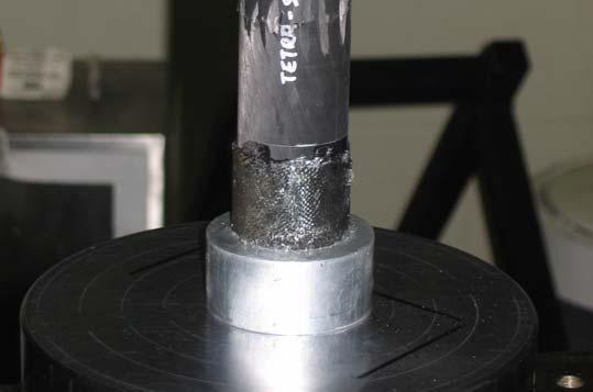
9 Figure 12. Graphite/Epoxy Seat Tube After Impact Figure 13. Graphite/Epoxy Seat Tube After Impact and Compression Testing
10 For further information contact Tom Foltz at or Specialty Materials, Inc. at or