Why silicon? Silicon oxide
|
|
|
- Caren Mason
- 5 years ago
- Views:
Transcription


1 Oxidation Layering. Oxidation layering produces a thin layer of silicon dioxide, or oxide, on the substrate by exposing the wafer to a mixture of highpurity oxygen or water at ca C (1800 F).
2 Why silicon? Silicon oxide Easy to grow Stable (chemically and thermally) Low Si/SiO 2 interface state density Good dielectric properties Abundant availability of Si in nature


3 Purpose of Oxidation Surface Passivation Chemical Physical Doping Barrier In Multi-Layer Structures Surface Dielectric Insulator between metals

4 Functions and Thickness of Oxide Layers
5 Three types of oxide Native oxide Slow oxidation in air at room temperature Thickness rarely exceeds 2 nm Usually considered a nuisance, a layer that has to be removed before processing Chemical oxide Less high-quality oxide Thermal oxide The best possible oxide Low interface state density Can be easily grown from several nm to a micron in thickness
6 Source: S.Wolf, R.H.Tauber, Silicon processing for the VLSI era, vol. 1: Process technology, 2 nd edition. SiO 2 looses its dielectric properties at thicknesses below approx nm SiO 2 has already reached this limit in high-end microprocessor applications, and is being replaced with high-k dielectrics (such as HfO 2 )
7 SiO 2 Properties Amorphous - no crystal structure (Crystalline SiO 2 is quartz.) Density gm/cm 3 Dielectric constant at low frequencies: 3.9 refractive index at optical wavelengths: n 1.5 Breakdown field: > 10 7 V/cm (1 V across 1 nm) The interface with silicon always results in electronic trap levels and some negative interface charge. Typical interface defect density cm -2.
8 SiO 2 Properties
9 Thermal oxidation growth of silicon dioxide Dry oxidation: Si (solid) + O 2 (gas) SiO 2 (solid) Steam (wet) oxidation: Si (solid) + H 2 O (gas) SiO 2 (solid) + 2H 2 (gas)


10 Dry Oxidation vs. Wet Oxidation Mind the Temperatures There is no difference whether water or hydrogen is added! No latency!

11 Oxidation Rate Wet Oxidation Dry Oxidation

12 Oxidation Rate (III)
")
13 Si Surfaces Si(100) Si(111)
14 Oxidation Rate (IV)
15 How to bring the hydrogen to the process? Water Bubbler Non-constant Rate Contamination Prone Needs Refills (Operator) Mixing of Hydrogen and Oxygen Gas in the Jungle Constant Mass Flow Clean No Refills Necessary
16 Mind when oxidizing! Hydrogen (Hydrogen/Oxygen mixtures) are explosive! Always use excess oxygen, so that hydrogen is oxidized away before exhaust. Care for proper ventilation of gas bottle cabinet! Very thin oxide layers can be improved adding chlorine. Use Cl 2, HCl, Trichlorethylene (TCE) or Trichlorethane (TCA). TCA most common. Scavenges contamination ions and heals defects. Use bubbler for TCA and TCE. Increases oxidation by a few percent.
17 Oxidation With Cl Containing Gas

18 Effect of HCl on Oxidation Rate
19 Dopant Redistribution During Thermal Oxidation (1) Dopant concentration Dopant concentration
20 Dopant Redistribution During Thermal Oxidation (2) Oxidation proceeds INTO silicon. Dopants choose silicon or oxide to reside in depending on their solubility. N-type dopants (phosphorus, antimony, arsenic) remain in Si Causes enrichment of layer below oxide Pile Up Causes less dense oxide above (especially for high phosphorus concentrations) P-type dopants (boron) go into oxide Causes depletion of the material below Dopants generally increase oxidation speed (up to 5 times with lots of P)
21 Dopant Redistribution During Thermal Oxidation (3)
22 Dopant Redistribution During Thermal Oxidation (4)
23 Dopant Redistribution During Thermal Oxidation (5) a) boron b) boron with hydrogen ambient c) Phosphorus d) gallium

24 Differential Oxidation Steps are generated! Different oxidation speed of different materials! Problem for multilayerstructures Silicon Wafer
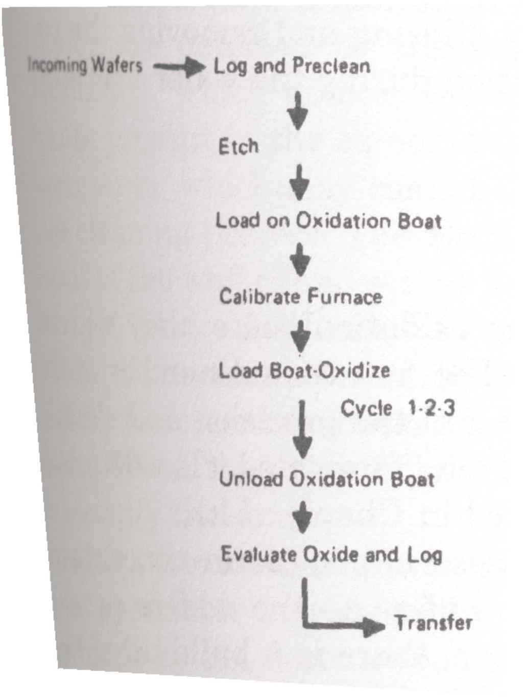
25 Oxidation: How to?
26 Oxidation and Furnace types Horizontal Tube Furnace Vertical Tube Furnace Rapid Thermal Processor High-Pressure Furnace Dry/Wet Oxidation Dry/Wet Oxidation Dry/Wet Oxidation Dry/Wet Oxidation
27 Horizontal Tube Furnace Advantage: Often already available Used for several processes Relatively simple Large Furnace area, lots of wafer at the same time Relatively cheap

28 Horizontal Tube Furnace

29 Horizontal Tube Furnace

30 Horizontal Tube Furnace Central flat region is used for oxidation Temperature control better than 1 deg. Constant gas flow for cleanliness and const. temp.
31 Horizontal Tube Furnace Reaction Chamber Inside heater elements there is the muffle (ceramic liner). Inside muffle, there is the reaction chamber. There inside go the wafer. Made from quartz (old) or SiC (new, heavy, expensive!) Quartz: Fragile, lets sodium pass, metallic contaminants, devitrifies over 1200C (small flakes falling on wafers) and sags (wafer boats don t move properly inside anymore). Large temp changes increase devitrification.periodic cleaning with HF bath or (plasma assisted) etching (NF 3 ) necessary.
32 Horizontal Tube Furnace Wafers are in boats, which are pushed on the paddle into the furnace. Problem 1: How to get wafers in boats? Problem 2: Sliding of paddle causes particle contamination Problem 3: Increasing wafer diameter needs larger furnace
33 Horizontal Tube Furnace Elephant is used to keep wafers clean while docking to the furnace.

34 How to Get Wafer on Paddle? Three complications: Wafer are usually put back to back in one slot Test wafer have to be sorted in and out afterwards No wafer contamination acceptable. Robotic systems can be better. Direct connection to cleaning tool.
35 Horizontal Tube Furnace How to put the wafers: Orthogonal to tube direction: Advantage: Dense packing, good throughput Disadvantage: No laminar flow between wafers. Inhomogeneous temperatures. Uneven reactant concentration. Large wafers require large tube diameters. Demixing of reactant gas. Along tube direction: Open packing, bad throughput

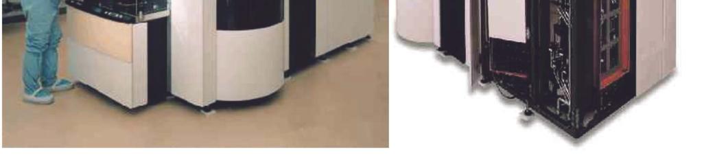
36 UCR s Cleanroom
37 Vertical Tube Furnace Advantage: Smaller footprint, less costly cleanroom space necessary. No demixing of process gas Easy rotation of wafers making process even more uniform Orientation of wafers same as in SMIF box (simple robotic system) No boat-scraping particles 60% more uniform processing Disadvantage: Costs (one vertical furnace = 4 row horizontal furnace) All 300 nm process use vertical furnaces!

38 Vertical Tube Furnace
 Long hot time grows dislocations No oxidation during ramp up or")
39 Horizontal Tube Furnace A typical process: Idle temp lower than process for slow heating (no warping of waver) Long hot time grows dislocations No oxidation during ramp up or down

40 High Pressure Furnaces Reduces Processing Time at High Temp. better throughput less growth of dislocations

41 Rapid Thermal Processing Usually single wafer Fast radiative heating of surface/ bulk is not brought to max temp. Less dislocations. Tube Furnace

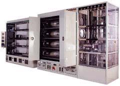
42 RTP/RTA systems Benchtop Production Scale Like CVD/PVD systems

43 Rapid Thermal Processing RTP Standard Wet Oxidation

44 Nitridation Works as oxidation Si 3 N 4 is formed Uses Ammonia Slow Potential application for thin gate oxides Oxonitrides, Nitroxides, Nitrided Oxides also possible Application in MEMS/NEMS
45 Quality of an Oxide Uniformity, Surface Roughness Etching Speed Mobile Ions Index of Refraction (important for capacitance) Rupture Hardness (strength)
46 Oxide Thickness
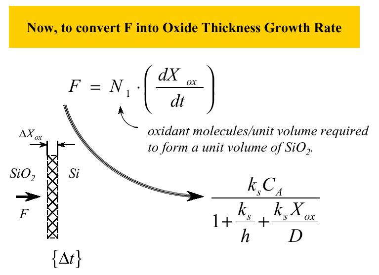
47 Deal-Grove Model
48 Oxide Growth Mechanism 1. Oxidant (O 2 ) reacts with silicon atoms 2. Silicon atoms are consumed by reaction 3. Layer of oxide forms on silicon surface 4.4 nm of silicon is consumed to grow 10 nm of SiO 2
49 Oxidation Mechanism
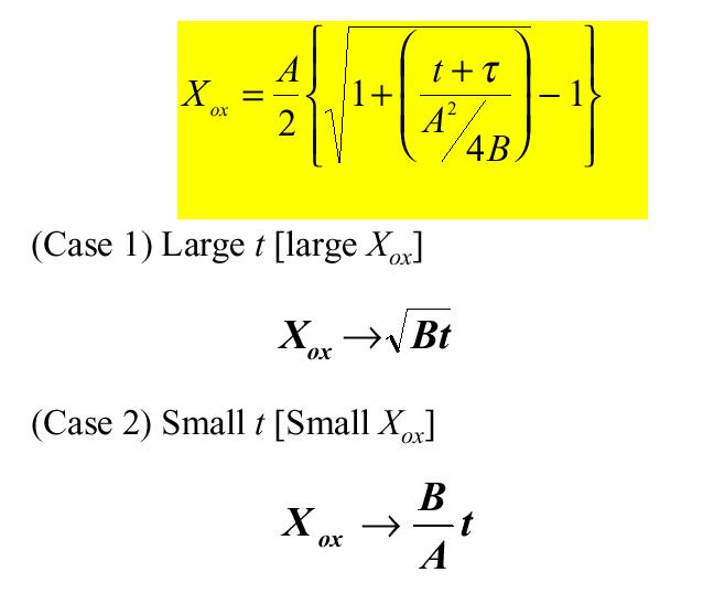
50 Deal-Grove Model (1)
51 Deal-Grove Model (2) B.E.Deal and A.S.Grove, J.Appl.Phys. 36, 3770 (1965)
52 Deal-Grove Model (3)
53 Deal-Grove Model (4)
54 Deal-Grove Model (5)
55 Deal-Grove Model (6)
56 Deal-Grove Model (7)
57 Deal-Grove Model (8)
 Limited by oxidant transport through the SiO 2")
58 Limiting cases in Si oxidation (a) (b) a) Interface reaction is the rate limiting step b) Limited by oxidant transport through the SiO 2 rate
59 Linear Growth Faster! Surface silicon atoms available Oxygen does not need to diffuse in bulk oxide. Si(111) oxidizes faster than Si(100) as more silicon is available per layer. Dry oxidation possible
60 Parabolic Growth Diffusion limited process >1000 A relevant Slower, e.g. 2000A in dryox =6 min, 4000A in dryox = 220 min both at 1200C Less difference between surfaces Wet oxidation or dryox with hydrogen addition required
61 Speeding up the parabolic oxidation Wet oxidation, using hydrogen/water - oxygen mixture instead of oxygen Hydroxyl enters the Si instead of oxygen Diffuses faster Subsequent bake in nitrogen necessary to drive excess H out. Remember If you have a rate problem in a solid state reaction: Add hydrogen!