Some thoughts on the nonlinearity of cracks in structural materials
|
|
|
- Darren Stephens
- 5 years ago
- Views:
Transcription
1 The Modelling and Simulation Centre The University of Manchester Some thoughts on the nonlinearity of cracks in structural materials John R Yates


2 Where, and what is, the crack tip? 2.0 mm 7.0 mm 2.0 mm 15.0 mm

3 Back to basics Real cracks are blunt, plastically deformed and have a failure process zone Crack growth is the permanent displacement of atoms from crack tip
4 Sources of non-linearity Plastic deformation Local to crack tip or globally Contact and closure of crack faces Residual stresses, roughness, oxide debris Changes in crack path Microstructure or macrostructure Multipleand competingcracking and damage mechanisms
5 Competing damage mechanisms Ductile void nucleation, growth and coalescence Inclusion cracking, debonding Transgranular and intergranular cleavage Fatigue growth Crystallographic shear in Stage I Stage II blunting Creep cavitation nucleation, growth and coalescence Corrosion Pitting Intergranular cracking Transgranular cracking Radiation
6 Crack tip events Wei Zhang, Yongming Liu. Int.J.Fat., In Press, 2011 Increasing load generates a sequence of local events from blunting to crack extension
7 Key question How can a single global parameter, K, dor J, correlate to such a complex set of mechanisms?
8 Global parametersvslocal events Function of d max, d min Function of J-Da response Function ofk max,k min Function ofk max

9 Tearing crack

10 2.5 mm Crack tip during tearing
11 Strategy If we can separatethe solid mechanics problem from the material failure problem, then we can use FEMto deal with the continuum mechanics and solve material stateproblem separately, at the appropriate length scale 11
12 Simplify the question Given the stresses and strains in this region of the structure, has the material locally failed by cleavage, ductile tearing, creep, fatigue, or corrosion?
13 How might we deal with the material statequestion? Consider a damage model for a given mechanism Rousselier s model for void growth Depends on stress state, deformation response and microstructure Has a characteristic length scale, L Calculate the state of the material over the volume L 3, using the local stresses and strains If the material is damaged, update the FE stiffness matrix
14 Multiple damage mechanisms Do each calculation independently and in parallel for each mechanism, But at its own length scale need to understand inter-relations and hierarchies to return loss of stiffness into FE model
15 Idea Combine Code_Aster for non-linear FEA with a site-bondmethod for the material states managed by Salome-Meca

16 Site-bond methods Smoothed particle hydrodynamics Cellular automata Pore models Lattice Boltzmann methods Peridynamics Key features coordination number of sites physical attributes of links: stiffness, strength, transport or any other property statistical variation of these parameters

17 Coordination number Cube, coordination = 6 Truncated octahedron, coordination = 14

18 Intergranularcrack propagation IntergranularSCC with ductile bridging ligaments Simulated 3D crack propagation with a lattice model Truncatedoctahedrawith variable grain boundary properties Failed boundaries shown; bridges appear as holes in crack surface Jivkov
19 General approach to fracture Ductile Cellular Automata arrays 2Rousseliermodels for different inclusion and precipitate distributions Shear array Low constraint shear model Brittle CA array divided into different cleavage nucleation micromechanisms
20 Architecture Cleavage fracture lattice of sites and bonds Ductile damage lattice Damage Damage Finite element mesh
21 New ideas Develop site-bond methods for Cleavage Fatigue Stress corrosion cracking Include nucleation, triaxiality, anisotropy and inhomogeneity
22 Site-bond approach to ductile fracture Sites = void formation region around inclusions Distribution of orientations, sizes, interfacial strengths, yield and hardening properties Bonds = matrix between voids Distribution of yield and hardening properties, and coalescence parameters Incorporate texture


23 Rousselier damage model Based on microstructure: inclusion size and spatial distributions void nucleation, growth and coalescence anisotropic hardening grain size and crystallographic orientation
24 Modification torousseliermodel Needleman model of nucleation By integration ofrousseliermodel using the modified damage variable the effects nucleation could be introduced
25 Cleavage modelling Weakest link model with grain size, orientation angle, and mis-orientation threshold assigned to each cell Fracture stress of each cell Propagation through grains and propagation from one cell to another
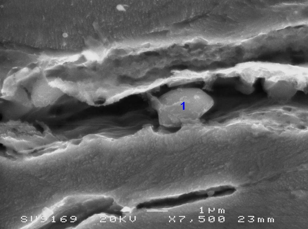

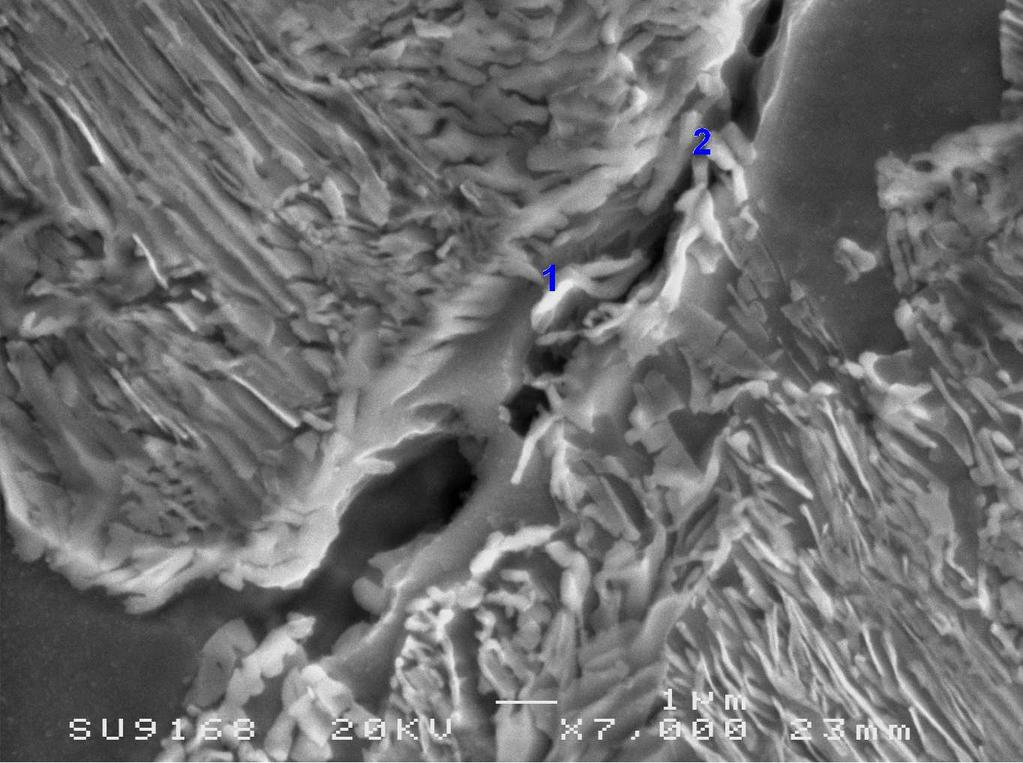

26 Cleavage nucleationmicromechanisms 1μm 1μm Inclusions in grains Pearlite-ferrite boundary 1μm 1μm Pearlite microstructure Cracked carbides

")
27 Microcracks at failure Maybe not a weakest link problem? 2 30μm (+25 o C) (-196 o C)
28 Site-bond approach to cleavage Sites = grains Distribution of orientations, sizes, lattice resistances, inclusions Bonds = grain boundaries Distribution of strengths, inclusions
29 Fatigue crack initiation Sites = grains Distribution of orientations, sizes, lattice resistances, inclusions Bonds = grain boundaries Distribution of strengths
30 Two processes in early fatigue Crack incubation Tanaka-Mura dislocation model. Incubation life related to macroscopic plastic strain range: Microstructurally small crack growth Navarro De Los Rios model of blocked dislocations Or Hobson-Brown Or Fatemi-Socie
31 Comments Non-linear crack behaviour arises from the many competing physical processes, each operating at different length and time scales, Site-bond methods offer the opportunity for better modelling and simulation
32 entres/masc