Designing Light Weight Structural Materials G.D. Hibbard
|
|
|
- Emma Baker
- 5 years ago
- Views:
Transcription
1 Designing Light Weight Structural Materials G.D. Hibbard Department of Materials Science and Engineering, University of Toronto, Canada

2


3 Our objective is to create new materials which fill the gaps in material property space.
4 Presentation Overview 1. Nanocrystalline Material Background: Start with Something Strong. 2. Selecting the Template: Cellular Architecture Background 3. Failure Mechanisms I: Bending-Dominated vs Buckling-Dominated Failure 4. Failure Mechanisms II: The Onset of Fracture 5. Other approaches: Lightweight Honeycombs 6. Summary
5 1. Nanocrystalline Materials: How do you design an ultra-high strength material?

6 1-dimensional lattice defect: dislocation.

7 Under applied shear stress dislocations transmit plastic deformation.
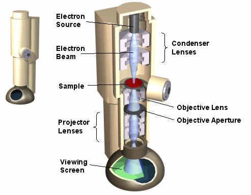
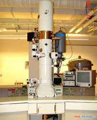
8 TRANSMISSION ELECTRON MICROSCOPY

9 Dislocation loops in a titanium alloy
10 Grain boundaries block dislocation motion.

11 Make material strong by shrinking crystals to nm-scale.
12 18 nm 24 nm 35 nm 80 nm >1 µm >10 µm I. Brooks, G. Palumbo, G. D. Hibbard, Z. Wang, U. Erb, J Mater Sci 46 (2011) 7713.

13 Intercrystalline Scaling A simple model based on space filling tetrakaidecahedra can be used to estimate the intercrystalline volume fraction as a function of grain size [Palumbo et al., Scripta Metall. Mater. 24 (1990) 1347].
14 1000 YIELD STRENGTH (MPa) 800 Yield strength increases significantly for grain sizes below 100 nm. Exhibits 䇾inverse䇿 HallPetch behaviour at grain sizes below 20 nm [Wang et al., Mat. Sci. Eng. A237 (1997) 150] GRAIN SIZE (nm)
15 Examples of synthesis methods: Biomolecular membrane Chemical reduction Chemical vapor condensation Cryogenic melting Crystallization of amorphous solids: Melt-spinning Splat-quenching Mechanical alloying Vapor deposition Electrodeposition Electrodeposition Gas condensation Thermal evaporation Electron beam Sputtering Laser ablation Plasma Mechanical alloying Mechanical attrition Powder Consolidation methods: Pressureless sintering Hot-isostatic pressing Explosive compaction Plasma activated sintering Dynamic magnetic compaction High pressure/low temperature sintering Reactive sputtering Severe plastic deformation: Equal channel-angular extrusion Torsion straining Accumulative roll-bonding Sol-Gel Spark erosion Spray conversion processing Broad range of synthesis techniques have been developed to produce nanoscale microstructures [see Shaw, JOM (USA) 52 (2000) 41].
16 Synthesis Method Classification Several possibilities: e.g. by chronological order, by product form/shape, by reaction mechanism. Two-step methods: nanostructured powder formation step followed by consolidation step. Inert gas condensation Mechanical attrition One-step methods: direct nanocrystalline formation step. Equal-channel-angular pressing Electrodeposition
17 Electrodeposition e- Power Supply Cathode: Mz+ + Ze- M e- Anode: M MZ+ + Ze- Electrosynthesis variables: Bath chemistry, ph Electrolyte flow Temperature Current density Waveform Non-line of sight deposition technique complex shapes. Considerable synthesis flexibility. Relatively inexpensive.
18 Nanocrystalline materials by electrodeposition x C Mex+ Mex+ Mex+ Mex+ Mex+ Nucleation Nucleation Mex+ Growth Growth CMex+ [Mex+] xe- xe- xe- Surface Diffusion xe- Surface diffusion
19
20 1000 YIELD STRENGTH (MPa) 800 Yield strength increases significantly for grain sizes below 100 nm. Exhibits 䇾inverse䇿 HallPetch behaviour at grain sizes below 20 nm [Wang et al., Mat. Sci. Eng. A237 (1997) 150] GRAIN SIZE (nm)
21 Early issue: limited tensile elongation 60 TENSILE ELONGATION (%) Early measurements showed very low tensile elongations to failure. [Wang et al., Mat. Sci. Eng. A237 (1997) 150] GRAIN SIZE (nm)


22 Nanocrystalline electrodeposition scale-up: ~575 HV200 Examples of electrodeposit surface roughness after 1 mm deposition. Dendrite formation must be prevented for thick electrodeposits: Conventional pulsing parameters, showing dendrite formation. Cross-section through a thick (> 5mm) nanocrystalline electrodeposit. Modified parameters, having smooth surface.


23 Poor process control Good process control
24

25

26
27 2. Cellular Architecture Background
")
28 [M.F. Ashby, Phil. Mag. 85 (2005) 3257]

29 Pin-jointed frame analogy in 2D M = b 2 j +3= 0 M <0 M =0 M >0 [M.F. Ashby, Phil. Mag. 85 (2005) 3257]


")
30 H. X. Zhu, J. F. Knott, N. J. Mills, J. Mech. Phys. Solids. 45 (1997) 319.

31 Stability criterion in 3D: M = b 3j +6 = 0 M = 36 3(24) + 6 = edges and 24 vertices: underconstrained pin-jointed frame. [Images from
 + 6 = 0 M = 12 3(6) + 6 = 0")

32 Tetrahedron Octahedron 6 edges; 4 vertices 12 edges; 6 vertices M = 6 3(4) + 6 = 0 M = 12 3(6) + 6 = 0 Low-density open-celled micro-truss architectures have been fabricated based on tetrahedral and octahedral geometries.

33 Low Density Open-cell Periodic Architectures Kagome Pyramidal Tetrahedral [H.N.G. Wadley, Phil. Trans. R. Soc. A 364 (2006) 31-68]
34 Architectural Effects M.F. Ashby, Phil. Trans. R. Soc. A (2006) 364, 15 30
35 3. Failure Mechanisms I: The Effect of Starting Cellular Architecture Metal/Metal Nanocrystalline Foams B.A. Bouwhuis, J.L. McCrea, G. Palumbo, G.D. Hibbard, Acta Materialia 57 (2009) Metal/Polymer Nanocrystalline Microtrusses L.M. Gordon, B.A. Bouwhuis, M. Suralvo, J.L. McCrea, G. Palumbo, and G.D. Hibbard, Acta Materialia, 57 (2009) 932.
36 EXAMPLE 1: Starting pre-form: 7.2% relative density AA6101 open cell foam. Significant n-ni thickness gradient through the electrodeposited foam. Electromagnetic shielding from outer ligaments limits coating deposition uniformity. [B.A. Bouwhuis, J.L. McCrea, G. Palumbo, G.D. Hibbard, Acta Materialia 57 (2009) 4046]
37 Large increase in compressive modulus and peak strength with increasing coating thickness. Decrease in load carrying capacity after peak.
 and wrinkling on compression side")
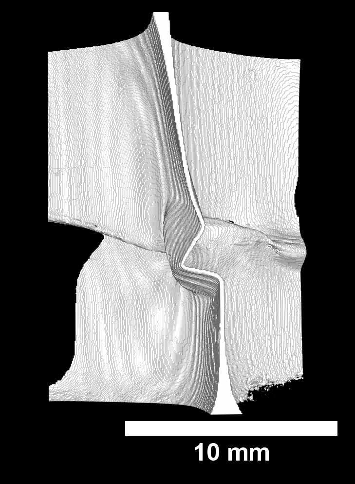
38 Sample pre-loaded to initial peak stress (ε 0.03). Failure occurred by strut rotation. Nanocrystalline sleeve fracture on tensile side (*) and wrinkling on compression side (**).

39 σ Foam n Ni =β Cσ YS,n Ni H 3 L Model based on plastic hinging collapse of a hollowtube n-ni foam able to account for strength increase with increasing sleeve thickness. Foam n Ni

. L.M. Gordon, B.A. Bouwhuis, M. Suralvo, J.L. McCrea, G.")
40 EXAMPLE 2: Rapid proto-typed pyramidal core electrodeposited with 20 nm grain size n-ni. Sleeve thickness controlled by deposition time (ranged from 15 to 60 µm). L.M. Gordon, B.A. Bouwhuis, M. Suralvo, J.L. McCrea, G. Palumbo, and G.D. Hibbard, Acta Materialia, 57 (2009)

41 Peak strength controlled by inelastic buckling of the core struts: axial rather than bendingdominated failure.

42 Post peak tensile fracture of face-sheet struts.
43 2 2 σcr,ni = k π Et,Ni INi l f Ni (a + 2t Ni )( b + 2t Ni ) 2 Model based on inelastic buckling strength able to account for increase in peak stress with increasing nanocrystalline sleeve thickness.


44 Specific strength increase provided by nanocrystalline tube network controlled by whether collapse is bending- or buckling-dominated. [Images from
45 4. Failure Mechanisms II: Sleeve Fracture Metal/Metal Nanocrystalline Microtrusses: n-ni/al microtrusses E. Bele, B.A. Bouwhuis, G.D. Hibbard, Acta Materialia 57 (2009) n-ni/steel microtrusses B.A. Bouwhuis, T. Ronis, J.L. McCrea, G. Palumbo, and G.D. Hibbard, Composites Science and Technology, 69 (2009)
46 n-ni/steel hybrids n-ni/al hybrids Large strength increases with n-ni coating thickness for both steel and Al cores.
47 n-ni/steel hybrids
48 n-ni/al hybrids


49 n-ni/steel hybrids No sign of sleeve fracture through post-buckling regime.


50 n-ni/al hybrids 17 µm 48 µm Early sleeve fracture with transition to hinge-dominated collapse mechanism with increasing thickness.
51 Hinge-dominated failure occurs through a combination of local buckling (plastic wrinkling) and sleeve fracture.
52 FE simulation of n-ni/al hybrids

53 FE simulation of n-ni/al hybrids
54 Hinge failure mechanism short-circuits inelastic buckling mechanism, lowering the achievable peak strength by ~10 to 20%.
 0.15 0.")
55 14 Peak Stress 12 σ (MPa) Onset of tensile strain at mid-strut Bifurcation stress ε (mm/mm) FE simulations can be used to investigate failure mechanisms and predict upper limiting strength.
 6 4 Steel Core Al Core Line of slope 1 2 0 0 2 4 6 8 10 12 Bifurcation Stress (MPa) While the Shanley model predicts the bifurcation stress and not the peak stress, both")
56 14 Peak Stress σ (MPa) 12 Peak Stress (MPa) Bifurcation stress ε (mm/mm) 6 4 Steel Core Al Core Line of slope Bifurcation Stress (MPa) While the Shanley model predicts the bifurcation stress and not the peak stress, both parameters experience virtually the same increase after nanocrystalline reinforcement

57 Analytical models can be used to predict the upper limiting buckling strength that can be provided by the nanocrystalline tube network over all possible strut and sleeve geometries.
58 5. Other approaches?


59

60 Advantages Higher Performance Integral webbing and face sheets Buttresses in web formation Low cost One-step manufacturing Green Low energy production Single material without adhesive


61 Fabrication Given the right combination of adhesion and viscosity, it is possible to melt stretch a sandwich panel with fully integrated core and face sheets in a single step. (a) (b) (c) 61

62

63

64 8% Relative Density 15% Relative Density 30% Relative Density

65
66 Effect of Sample Height Effect of Areal Density

67
68
69 6. Summary Designing new types of lightweight structural composites means combining internal architectures with material structures. Key issue is in understanding the failure mechanisms across a multiplicity of length scales.
70