Capillary-driven topography and microstructure evolution in metals: matching experiment with theory
|
|
|
- Dora Oliver
- 5 years ago
- Views:
Transcription
1 Capillary-driven topography and microstructure evolution in metals: matching experiment with theory E. Rabkin, L. Klinger, D. Amram, O. Malyi Dept. of Materials Science and Engineering, TECHNION, Haifa, Israel Outline: -Thermodynamics of curved surfaces; -Grain boundary grooving; -The interplay of grooving and boundary migration; jerky motion; -Thermodynamics of strongly anisotropic surfaces; -Grain boundary grooving with anisotropy; -Solid state dewetting of thin films, single crystal particles; -Bicrystal-single crystal transformation during dewetting; -Microstructural factors in dewetting.
2 Thermodynamics of curved surfaces
3 Surface movement by surface diffusion Surface diffusion flux: j s ν Ds µ s = kt s Normal displacement of the surface: 2 n js ν DsΩ µ s = Ω = 2 t s kt s Example: small slope approximation (Mullins equation): t kt x 2 4 y ν DsΩ y = 4 When all surface atoms are mobile, νω=δ (thickness of surface layer)
4 γ S θ γ S Grain boundary grooving γ γ b = 2 S L cosθ ( ) 1/ Bt L γ b GB t annealing time B Mullins constant: B = δd S Ωγ kt D s surface diffusion coefficient S Mechanism of groove growth: curvature-driven surface diffusion (Mullins, 1957)
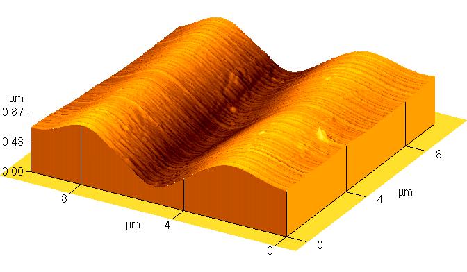
![Energy of Σ19a<011> GB in Cu bicrystal 950 nm 0 nm 50 µm 800 600 25 µm z [nm] 400 200 0 µm 25 µm 0 µm 50 µm 0 Σ19a GB](/docs-images/93/111953085/images/5-0.jpg "groove -20-10 0 10 20 x [µm] Good quality of AFM-measured surface morphology allows direct fitting by Mullins")
5 Energy of Σ19a<011> GB in Cu bicrystal 950 nm 0 nm 50 µm µm z [nm] µm 25 µm 0 µm 50 µm 0 Σ19a GB groove x [µm] Good quality of AFM-measured surface morphology allows direct fitting by Mullins function


6 TECHNION - Department of Materials Engineering GB migration vs. grooving 50 µm

7 Jerky motion of grain boundaries Ghost lines are the witnesses of grain boundary jerky motion formed by mechanism of surface diffusion LM

8 GB groove at the original position Blunted root! The GB has deviated from its original position
9 Decay of sinusoidal surface corrugation A/ A 0 A λ Mullins theory: 4 2π = exp B t λ or ( A A ) ln / Bt λ 0 4 Z, nm GB migration X, µm
10 Quantification of GB jerky motion Hump amplitude, nm lna n = *n Hump number Time interval between two successive GB jumps: t=3.5 s 28 ghost lines=100 s of total migration time Reconstructed sequence of events: 58.5 min at orig. position 1.5 min of jerky motion to final pos.


11 Most metals are anisotropic: both surface energy and surface self-diffusion depend on surface orientation Au on sapphire, Kaplan & Sadan, 2006 My messages: Pt nanoparticles, Ahmadi et al., Isotropic models and handbook surface diffusivities are worthless in predicting surface morphologies of anisotropic metals; -Many features of strongly anisotropic surfaces can be understood in the framework of simple models allowing only well-defined facets.
12 Thermodynamics of strongly anisotropic surfaces W.C. Carter, et al. Acta metall mater 1995; 43:4309. Weighted mean curvature (WMC): L δn δ G µ ( x, y) δnda 1 µ = µ ( x, y) da A δg µ =Ω δv Ω = WMC=4γ L δn / L 2 δn = 4γ/L The chemical potential averaged along the facet is equal to WMC
 0.0-0.2-0.")
13 Example 1: GB grooving at strongly anisotropic surfaces GB grooving in NiAl at 1400 C 0.2 y (µm) Facet x (µm) Apparent negative, concave curvature at the groove root!
 Groove wall that does not exhibit any")
14 One more wrong image δθ 0.1 y (µm) Facet x (µm) Groove wall that does not exhibit any curvature!
 At the final GB position a hillock is formed")
15 And another one FGB OGB y (µm) x (µm) At the final GB position a hillock is formed instead of a groove!
16 Theory of GB grooving with anisotropy y Facet y = By'''' For non-sing. surface 0 ξ x α δθ GB WMC for singular facet 2 n ν D s Ω µ = s 2 t kt s The facet moves parallel to itself: µ = s a0 a1s a2s
17 The results (d=d facet /D S ) y/(bt) 1/ (a) d=0 d=0.01 d=0.1 d>> y/(bt) 1/ (b) d=0 d=0.01 d=0.1 d>> x/(bt) 1/4 x/(bt) 1/4 For d 0 the morphology is Mullins-like, but with the different value of θ The formation of hillock is driven by the decrease of total interfacial energy
18 Solid state dewetting of thin films, final stage Film Substrate T Minimization of surface/interface energy For T<T m,the process is surface diffusion controlled - solid state dewetting Consequences and application examples Electronic devices: failure due to overheating Nanostructuring (catalysts, sensors) : self-organization process

19 Au Sapphire Dewetting of isotropic single crystalline film, initial stage Depression Depression H. Wong et al., Acta mater., 2000 Shedding mass mechanism Particle Particle
 Pole figure (110) Pole figure (111) Very thin Fe underlayer allows producing a quasi-single crystal Au")
20 Au, Fe thin films, and Au/Fe bi-layers on sapphire Au Fe Au-Fe bilayer Pole figure (111) Pole figure (110) Pole figure (111) Very thin Fe underlayer allows producing a quasi-single crystal Au film

21 TECHNION - Department of Materials Engineering Thermal stability: poly- vs single crystalline Au films 9 nm Au on 3 nm Fe 9 nm Au Annealed at 650 C for 7 h For producing particles: 48 h at 900 C 1 h at 650 C The role of grain boundaries?

22 Final stages of Au film dewetting (particles) We followed the size and shape changes of individual particles
23 0 h Single crystalline particles are extraordinarily stable 950 C, in air 1 h 150 0h 1h 11h 65h Height, nm h 65 h Length, nm 0h 1h 11h 65h (e) Height, nm Width, nm (f)
24 Bi-crystalline particles readily change their size and shape 0 h 1 h Rotation 0 h 1 h
25 Bi-crystal single crystal transformation
. Movement of large faceted bump is slow Chatain & Wynblatt, Interf. Sci.")
26 Why faceted single crystal particles are so stable? Coupled diffusion/surface islands nucleation may be difficult (Mullins & Rohrer, J. Amer. Ceram. Soc., 2000). Movement of large faceted bump is slow Chatain & Wynblatt, Interf. Sci., 2004: equilibration of Cu particles on sapphire is slow
27 The model of bi-crystal single crystal transformation Fast diffusion along the nonsingular surfaces causes rotation
28 Numerical simulations of surface diffusion: model crystal Surface energy Surface diffusion (a) (b) γ-plot and D-plot Equilibrium shape
29 Numerical simulations of surface diffusion: results 3 2 initial Y 1 GB 0 final X Estimated surface self-diffusion coefficient along the non-singular surfaces at 950 C: D s m 2 /s
 (0001) Au [211] [1120] Au Al O 2 3 Al O 2 3 PF of")

30 Why the grain boundary migrated? (111) (0001) Au [211] [1120] Au Al O 2 3 Al O 2 3 PF of as-deposited Au film PF of Au film dewetted at 850 C for 24 h in-plane texturing Details in: Amram & Rabkin, Acta mater 61 (2013) pp


31 Dewetting of polycrystalline Au films 14 nm-thick Au film, 350 C in air 55 min 70 min Grain boundaries accelerate dewetting by transforming singular surfaces into non-singular ones
32 Single crystal particles: evaporation 0 h 1 h The particles of low height shrink laterally. No changes in height 11 h 27 h Particle 1: h 1 =26.5 nm Particle 2: h 2 =102.2 nm Particle 3: h 3 =69.4 nm 65 h
33 Shrinking vs. stable particles About 20 % of single crystalline particles shrink laterally
34 Statistics of shrinking particles (b) All particles Evaporation 40 (c) All particles Evaporation Frequency Frequency Particle size, nm Particle height, nm The height of the particle determines its fate!
35 Evaporation: why the particle height is so stable? G f G f G G e f G G e f α sinαcosα = π α G e Surface diffusion on top surfaces is prohibited Diffusion on side facets is allowed, but significantly slowed down by nucleation barrier
36 Evaporation: the model γ i γ s + γ F 2γ F µ F = µ 0 +Ω + h a Boundary conditions: J(y=0)=0; µ(y=h)=µ 0. For h<<a, v ( ) 2 3D s νω γ i γ s + γ F 1 kt h 3
37 Kinetics of shrinkage n v h Velocity, nm/h Height, nm n = 2.9 ± 0.3 D s 3.2± m 2 /s Compare with D s m 2 /s for non-singular surfaces The self-diffusion along singular surfaces is six (!) orders of magnitude lower than along the non-singular ones


38 Dewetting of anisotropic single crystalline Au-Fe bi-layers 7h 15h C * micrographs are in-scale. Kinetic model: Amram, Klinger & Rabkin, Acta mater 60 (2012) 3047 D s 1.0± m 2 /s Comparable with literature values for nonsingular surfaces Where is the source of defects?
 (111) Height, nm")

39 Film topography in the vicinity of a hole Non-singular Height, nm (111) (111) Height, nm Distance, nm Distance, µm Who supplies the defects to the hole edge?


40 High-resolution TEM of the film edge HAADF STEM micrograph TEM micrograph + FFT of the edge front Where did it go? Twin boundaries generate defects!


41 Depinning of twin boundaries h 0 h 0 The edge movement stops once the twin depins from the edge, forming a layer of 9R phase


 Ni (edge) (2)")
42 Twinning is a general phenomenon in dewetting Ni thin film, 80 nm in thickness, 5 h at 1000 C 60 (twin) Sapphire (1) Ni (edge) (2) Ni (film) (3)

43 Antropic principle in Materials Science? In philosophy: Brandon Carter, 1973:
44 Thank you!