Novel Slurry Injection System for Reduced Slurry Usage and Enhanced CMP Performance. Ara Philipossian [Araca Incorporated, Tucson AZ USA]
|
|
|
- Harold Moore
- 5 years ago
- Views:
Transcription

1 Novel Slurry Injection System for Reduced Slurry Usage and Enhanced CMP Performance Ara Philipossian [Araca Incorporated, Tucson AZ USA]
2 Problem Statement Slurries are expensive and reducing their flow rate is among the top objectives of any CMP module leader and fab manager. Slurries vary in chemical and physical properties and they rely on different mechanisms for removal. Therefore, a simple reduction in slurry flow without understanding the nature of the slurry, and without fundamentally changing the method of slurry dispense, can cause adverse effects such as: Lower RR Higher WIWRRNU Higher wafer-level polishing defects Slower displacement of rinse water from the pad surface Each IC fab employs different processes and different sets of consumables (i.e. slurry, pad and conditioning discs). Therefore no universal technological solution exists for slurry flow rate reduction.
3 Effect of Rinsing Between Polishes (ILD) 2700 Removal Rate (A/min) No Rinse Between Polishes Rinse Between Polishes Slurry Flow Rate (ml/min)
4 The Slurry Injection System (SIS) Araca Incorporated has developed, and is selling, novel slurry injection systems for: Applied Materials Mirra and Reflexion LK Ebara EPO-222 Ebara F-REX200 series Ebara F-REX300 series SpeedFam IPEC 472 Compared with standard slurry application methods (i.e. dispensing the slurry near the center of the pad or through a plurality of holes sprayed over the pad radius), SIS provides: Higher material removal rate at the same slurry flow rate Same material removal rate at a lower slurry flow rate Equivalent or lower wafer-level polishing defects In this presentation, we highlight our latest results on the performance of the SIS technology with on various polishing platforms.


5 SIS for the Reflexion LK Polisher Quick disconnect and three hand screws for pad change
6 RR and Wafer-Level Defects Blanket 300 mm TEOS CMP Blanket 300 mm Copper CMP Defects (Copper CMP) Wafer Mini-Marathon SIS Point Application Total Defects Scratches Area Defects

7 SIS for the F-REX200 Polisher
8 RR and Wafer-Level Defects Blanket 200 mm TEOS CMP Blanket 200 mm TEOS CMP 2000 SIS Point Application Removal Rate (A/min) % Slurry Flow Rate Reduction Normalized Defect Count 0.1 Point Application SIS 25 Wafer Mini-Marathon LPD Area Defects Slurry Flow Rate (ml/min)

9 SIS for the SpeedFam-IPEC 472 Polisher


10 RR and Wafer-Level Defects Blanket TEOS 25 Wafers Mini-Marathon

11 SIS Principle of Operation Injector bottom is made of PEEK or PPS. It contacts the pad. The air interface is eliminated; this means no dry slurry build-up. Injector Pad Fresh slurry is applied between the injector bottom and the pad through a thin fluid layer. SIS can be configured to inject at multiple points to accommodate pad grooving differences. SIS is flexible and it conforms to the pad as the pad wears over time. Wafer SIS squeegees the pad and significantly reduces the chances of the following to reenter the pad-wafer interface: Pad rinse water Used slurry Reaction products Foam Pad debris and particles
12 Bow Wave Characterization Bow wave is formed at the retaining ring due to tortuosity in the pad-wafer interface. Higher bow wave at the retaining ring suggests greater slurry wastage as only a FIXED amount of slurry can enter the pad-wafer interface due to the slit design of the retaining ring. With Point Application bow wave at the retaining ring is comprised of mixed old and new slurry along with water, pad debris, foam and particles! With SIS the bow wave is mostly made of FRESH slurry! SIS Point Application SIS


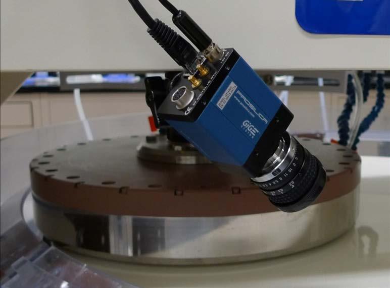
13 Araca s UVIZ-100 UV Fluorescence System d


14 Bow Wave Thickness Results Point Application 150 cc per min Top 25 RPM Bottom 51 RPM SIS 150 cc per min Top 25 RPM Bottom 51 RPM


15 UVIZ-100 Image Browsing Software


16 Bow Wave Thickness Measurement Carrier Head Carrier Head Carrier Head Raw Image 1 Frame Bow Wave Bow Wave Bow Wave Pad Grey Scale Image Cropped Image


17 UVIZ-100 Image Analysis Software Example: 150 Frames of the Video Point Application SIS-100
 Maximum (mm) Minimum (mm) Point Application 0.38 0.74 0.28 SIS 0.23 0.24 0.")
18 Film Thickness Calibration and Results Injection Method Mean Bow Wave Thickness (mm) Maximum (mm) Minimum (mm) Point Application SIS


19 Flow Patterns 10s After Start of Slurry Point Application 150 cc per min 25 RPM SIS 150 cc per min 25 RPM
20 Summary SIS significantly reduces slurry flow rate without adversely impacting RR. Defects are much lower than those observed at the POR flow rate using Point Application. Alternatively, SIS may be used to increase RR and decrease defects at the POR slurry flow rate. SIS is totally passive and can be added to existing polisher hardware in the most non-intrusive manner and be removed in less than 2 minutes during pad changes. Compared to POR, typical slurry savings of 25 to 50 percent are observed on all polisher models tested. Slurry film thickness at the bow wave is successfully measured by the UVIZ-100 UV fluorescence system. Results indicate that SIS generates a significantly thinner slurry film at the bow wave than Point Application. As such the SIS the bow wave is mostly made of FRESH slurry which increases RR. By eliminating the slurry-air interface and by moving the bow wave containing debris, foam and pad fragments away from the retaining ring and to the upstream of the SIS, particles are also reduced.