ESR-3574* Issued December 1, 2013 This report is subject to renewal August 1, 2014.
|
|
|
- Cody Ward
- 5 years ago
- Views:
Transcription
1 ICC-ES Evaluation Report (800) (56) ESR-574* Issued December, 0 This report is subject to renewal August, 04. A Subsidiary of the International Code Council DIVISION: CONCRETE Section: Concrete Anchors DIVISION: METALS Section: Post-Installed concrete anchors REPORT HOLDER: HILTI, INC SOUTH ND EAST AVENUE TULSA, OKLAHOMA 7446 (800) HiltiTechEng@us.hilti.com EVALUATION SUBJECT: HILTI HIT-HY 00 ADHESIVE ANCHORING SYSTEM IN UNCRACKED CONCRETE.0 EVALUATION SCOPE Compliance with the following codes: 009 and 006 International Building Code (IBC) 009 and 006 International Residential Code (IRC) Property evaluated: Structural.0 USES The Hilti HIT-HY 00 Adhesive Anchoring System is used to resist static, wind, or earthquake (Seismic Design Categories A and B only) tension and shear loads in uncracked normal-weight concrete having a specified compressive, f c, of,500 psi to 8,500 psi (7. MPa to 58.6 MPa). The anchor system is an alternative to cast-in-place anchors described in Sections 9 and 9 of the 009 and 006 IBC. The anchor systems may also be used where an engineered design is submitted in accordance with Section R0.. of the IRC..0 DESCRIPTION. General: The Hilti HIT-HY 00 Adhesive Anchoring System is comprised of the following components: Hilti HIT-HY 00 adhesive packaged in foil packs. Adhesive mixing and dispensing equipment. Hole cleaning equipment. The Hilti HIT-HY 00 Adhesive Anchoring System may be used with continuously threaded rod, Hilti HIS-N and HIS-RN internally-threaded inserts or deformed reinforcing bar. The primary components of the Hilti Adhesive Anchoring System are shown in Figure of this report. The manufacturer s printed installation instructions (MPII), as included with each adhesive unit package, are shown in Figure 5 of this report.. Materials:.. Hilti HIT-HY 00 Adhesive: Hilti HIT-HY 00 Adhesive is an injectable hybrid adhesive combining urethane methacrylate resin, hardener, cement and water. The resin and cement are kept separate from the hardener and water by means of a dual-cylinder foil pack attached to a manifold. The two components combine and react when dispensed through a static mixing nozzle attached to the manifold. Hilti HIT-HY 00 is available in.-ounce (0 ml) and 6.9-ounce (500 ml) foil packs. The manifold attached to each foil pack is stamped with the adhesive expiration date. The shelf life, as indicated by the expiration date, applies to unopened foil packs that are stored in accordance with the manufacturer s printed installation instructions (MPII), as illustrated in Figure 5 of this report... Hole Cleaning Equipment: Hole cleaning equipment comprised of steel wire brushes and air nozzles is illustrated in Figure 5 of this report... Dispensers: Hilti HIT-HY 00 must be dispensed with manual dispensers or electric dispensers provided by Hilti...4 Anchor Elements:..4. Threaded Steel Rods: The threaded steel rods must be clean, continuously threaded rods (all-thread) in diameters as described in Tables 6 and 9 of this report. Steel design information for common grades of threaded rod and associated nuts are provided in Tables and 4, and instructions for use are shown in Figure 5. Carbon steel threaded rods must be furnished with a inchthick (0.005 mm) zinc electroplate coating in accordance with ASTM B6 SC ; or must be hot-dipped galvanized in accordance with ASTM A5, Class C or D. Threaded rods must be straight and free of indentations or other defects along their length. The ends may be stamped with identifying marks and the embedded end may be blunt cut or cut on the bias (chisel point)...4. Steel Reinforcing Bars: Steel reinforcing bars are deformed reinforcing bars as described in Table 5 of this report. Table 6, Table 9 and Table, along with the instructions for use shown in Figure 5 of this report, *Revised January 04 ICC-ES Evaluation Reports are not to be construed as representing aesthetics or any other attributes not specifically addressed, nor are they to be construed as an endorsement of the subject of the report or a recommendation for its use. There is no warranty by ICC Evaluation Service, LLC, express or implied, as to any finding or other matter in this report, or as to any product covered by the report. Copyright 04 Page of 000
2 ESR-574 Most Widely Accepted and Trusted Page of summarize reinforcing bar size ranges. The embedded portions of reinforcing bars must be straight, and free of mill scale, rust, mud, oil, and other coatings that may impair the bond with the adhesive. Reinforcing bars must not be bent after installation except as set forth in Section 7.. of ACI 8, with the additional condition that the bars must be bent cold, and heating of reinforcing bars to facilitate field bending is not permitted...4. HIS-N and HIS-RN Inserts: Hilti HIS-N and HIS-RN inserts have a profile on the external surface and are internally threaded. Tensile properties for HIS-N and HIS-RN inserts are provided in Table of this report. The inserts are available in diameters as shown in Table 5, and the instructions for use are shown in Figure 5 of this report. HIS-N inserts are produced from carbon steel and furnished with a inch-thick (0.005 mm) zinc electroplated coating complying with ASTM B6 SC. The stainless steel HIS-RN inserts are fabricated from X5CrNiMo7 K700 steel complying with DIN 7440 (EN 0088). Specifications for common bolt types that may be used in conjunction with HIS-N and HIS-RN inserts are provided in Table 4. Bolt grade and material type (carbon, stainless) must be matched to the insert. Strength reduction factors,, corresponding to brittle steel elements must be used for HIS-N and HIS-RN inserts Ductility: In accordance with ACI 8 D., in order for a steel element to be considered ductile, the tested elongation must be at least 4 percent and reduction of area must be at least 0 percent. Steel elements with a tested elongation of less than 4 percent or a reduction of area less than 0 percent, or both, are considered brittle. Values for various steel materials are provided in Tables through 5 of this report. Where values are nonconforming or unstated, the steel must be considered brittle.. Concrete: Normal-weight concrete must comply with Sections 90 and 905 of the IBC. The specified compressive of the concrete must be from,500 psi to 8,500 psi (7. MPa to 58.6 MPa). 4.0 DESIGN AND INSTALLATION 4. Strength Design: 4.. General: The design of anchors under the 009 and 006 IBC, as well as the 009 and 006 IRC, must be determined in accordance with ACI 8- (ACI 8) and this report. A design example according to the 009 IBC based on ACI 8- is given in Figure 4 of this report. Design parameters are based on the ACI 8- for use with the 009 and 006 IBC unless noted otherwise in Sections 4.. through 4.. of this report. The design of anchors must comply with ACI 8 D.4.. Design parameters are provided in Table 6 through Table 7. Strength reduction factors,, as given in ACI 8- D.4. must be used for load combinations calculated in accordance with Section 605. of the 009 or 006 IBC or Section 9. of ACI 8. Strength reduction factors,, as given in ACI 8- D.4.4 must be used for load combinations calculated in accordance with ACI 8 Appendix C. 4.. Static Steel Strength in Tension: The nominal static steel of a single anchor in tension,, in accordance with ACI 8 D.5.. and the associated reduction factors,, in accordance with ACI D.4. are provided in the tables outlined in Table for the corresponding anchor steel. 4.. Static Concrete Breakout Strength in Tension: The nominal static concrete breakout of a single anchor or group of anchors in tension, N cb or N cbg, must be calculated in accordance with ACI 8 D.5. with the following addition: The basic concrete breakout of a single anchor in tension, N b, must be calculated in accordance with ACI 8 D.5.. using the values of k c,uncr as provided in Tables 7, 0, and 6 in this report. Where analysis indicates no cracking in accordance with ACI 8 D.5..6, N b must be calculated using k c,uncr and Ψ c,n =.0. See Table. For anchors in lightweight concrete, see ACI 8- D..6. The value of f c used for calculation must be limited to 8,000 psi (55 MPa) in accordance with ACI 8 D..7. Additional information for the determination of nominal bond in tension is given in Section 4..4 of this report Static Bond Strength in Tension: The nominal static bond of a single adhesive anchor or group of adhesive anchors in tension, N a or N ag, must be calculated in accordance with ACI 8- D.5.5. Bond values are a function of the concrete compressive, the concrete temperature range, and the installation conditions (dry or water-saturated concrete). The resulting characteristic bond shall be multiplied by the associated reduction factor nn as follows: CONCRETE TYPE Uncracked PERMISSIBLE INSTALLATION CONDITIONS BOND STRENGTH ASSOCIATED STRENGTH REDUCTION FACTOR Dry uncr d Water-saturated uncr ws Figure of this report presents a bond design selection flowchart. Strength reduction factors for determination of the bond are given in the tables outlined in Table of this report. Adjustments to the bond may also be taken for increased concrete compressive as noted in the footnotes to the corresponding tables Static Steel Strength in Shear: The nominal static steel of a single anchor in shear as governed by the steel,, in accordance with ACI 8 D.6.. and reduction factor,, in accordance with ACI 8 D.4. are given in the tables outlined in Table of this report for the corresponding anchor steel Static Concrete Breakout Strength in Shear: The nominal static concrete breakout of a single anchor or group of anchors in shear, V cb or V cbg, must be calculated in accordance with ACI 8 D.6. based on information given in the tables outlined in Table of this report for the corresponding anchor steel. The basic concrete breakout of a single anchor in shear, V b, must be calculated in accordance with ACI 8 D.6.. using the values of d given in the tables outlined in Table for the corresponding anchor steel in lieu of d a (009 IBC) and d o (006 IBC). In addition, h ef must be substituted for l e. In no case must l e exceed 8d. The value of f c must be limited to a maximum of 8,000 psi (55 MPa) in accordance with ACI 8 D Static Concrete Pryout Strength in Shear: The nominal static pryout of a single anchor or group of anchors in shear, V cp or V cpg, shall be calculated in accordance with ACI 8 D.6..
3 ESR-574 Most Widely Accepted and Trusted Page of 4..8 Interaction of Tensile and Shear Forces: For designs that include combined tension and shear, the interaction of tension and shear loads must be calculated in accordance with ACI 8 D Minimum Member Thickness, h min, Anchor Spacing, s min, and Edge Distance, c min : In lieu of ACI 8 D.8. and D.8., values of s min and c min described in this report must be observed for anchor design and installation. In lieu of ACI 8 D.8.5, the minimum member thicknesses, h min, described in this report must be observed for anchor design and installation. For adhesive anchors that will remain untorqued, ACI 8 D.8.4 applies. For the edge distance c ai and anchor spacing, s ai, and maximum torque, T max shall comply with the following requirements: Edge Distance c ai Reduced Installation Torque T max,red for Edge Distances c ai < (5 x d a ) Minimum Anchor Spacing, s ai => Maximum Torque, T max,red.75 in. (45 mm) 5 x d a s ai < 6 in. 0. x T max c ai < 5 x d a s ai 6 in. (406 mm) 0.5 x T max 4..0 Critical Edge Distance c ac : In lieu of ACI 8 D.8.6, c ac must be determined as follows: c ac =h ef τ uncr h h ef where need not be taken as larger than.4; and (D-4) τ uncr = characteristic bond stated in the table of this report where by τ uncr need not be taken as larger than: 4.. Requirements for Seismic Design: The anchors may be used to resist seismic loads for structures classified as Seismic Design Categories A and B under the IBC or IRC. 4. Installation: Installation parameters are illustrated in Figure of this report. Installation must be in accordance with ACI 8- D.9. and D.9.. Anchor locations must comply with this report and the plans and specifications approved by the code official. Installation of the Hilti HIT-HY 00 Adhesive Anchor System must conform to the manufacturer s printed installation instructions (MPII) included in each unit package as provided in Figure 5 of this report. 4. Special Inspection: Periodic special inspection must be performed where required in accordance with Sections and of the 009 IBC or Section 704. of the 006 IBC and this report. The special inspector must be on the jobsite initially during anchor installation to verify anchor type, anchor dimensions, adhesive identification and expiration date, concrete type, concrete compressive, hole dimensions, hole cleaning procedures, anchor spacing, edge distances, concrete thickness, anchor embedment, tightening torque and adherence to the manufacturer s printed installation instructions. The special inspector must verify the initial installations of each type and size of adhesive anchor by construction personnel on-site. Subsequent installations of the same anchor type and size by the same construction personnel shall be permitted to be performed in the absence of the special inspector. Any change in the anchor product being installed or the personnel performing the installation requires an initial inspection. For ongoing installations over an extended period, the special inspector shall make regular inspections to confirm correct handling and installation of the product. Continuous special inspection of adhesive anchors installed in horizontal or upwardly inclined orientations to resist sustained tension loads shall be performed in accordance with ACI 8 D Under the IBC, additional requirements as set forth in Sections 705, 706, or 707 must be observed, where applicable. 5.0 CONDITIONS OF USE The Hilti HIT-HY 00 Adhesive Anchoring System described in this report is a suitable alternative to what is specified in, those codes listed in Section.0 of this report, subject to the following conditions: 5. The Hilti HIT-HY 00 Adhesive Anchoring System must be installed in accordance with the manufacturer s printed installation instructions as included in the adhesive packaging and illustrated in Figure 5 of this report. 5. Anchors are limited to installation in concrete that is uncracked and may be expected to remain uncracked for the service life of the anchor. The anchors must be installed in uncracked normal-weight concrete having a specified compressive f c =,500 psi to 8,500 psi (7. MPa to 58.6 MPa). 5. The values of f c used for calculation purposes must not exceed 8,000 psi (55 MPa). 5.4 Anchors must be installed in concrete base materials in holes predrilled in accordance with the instructions provided in Figure 5 of this report. 5.5 Loads applied to the anchors must be adjusted in accordance with Section 605. of the IBC for design. 5.6 Hilti HIT-HY 00 adhesive anchors are recognized for use to resist short- and long-term loads, including wind and earthquake (Seismic Design Categories A and B only), subject to the conditions of this report. 5.7 Strength design values must be established in accordance with Section 4. of this report. 5.8 Minimum anchor spacing and edge distance as well as minimum member thickness must comply with the values given in this report. 5.9 Prior to anchor installation, calculations and details demonstrating compliance with this report shall be submitted to the code official. The calculations and details must be prepared by a registered design professional where required by the statutes of the jurisdiction in which the project is to be constructed. 5.0 Anchors are not permitted to support fire-resistive construction. Where not otherwise prohibited by the code, the Hilti HIT-HY 00 Adhesive Anchoring System is permitted for installation in fire-resistive construction provided that at least one of the following conditions is fulfilled: Anchors are used to resist wind or seismic forces only.
4 ESR-574 Most Widely Accepted and Trusted Page 4 of Anchors that support gravity load bearing structural elements are within a fire-resistive envelope or a fire-resistive membrane, are protected by approved fire-resistive materials, or have been evaluated for resistance to fire exposure in accordance with recognized standards. Anchors are used to support nonstructural elements. 5. Since an ICC-ES acceptance criteria for evaluating data to determine the performance of adhesive anchors subjected to fatigue or shock loading is unavailable at this time, the use of these anchors under such conditions is beyond the scope of this report. 5. Use of zinc-plated carbon steel threaded rods, zinc-plated HIS-N inserts, or steel reinforcing bars is limited to dry, interior locations. 5. Use of hot-dipped galvanized carbon steel or stainless steel rods, or stainless steel HIS-RN inserts, is permitted for exterior exposure or damp environments. 5.4 Steel anchoring materials in contact with preservativetreated and fire-retardant treated wood must be of zinc-coated carbon steel or stainless steel. The minimum coating weights for zinc-coated steel must comply with ASTM A Periodic special inspection must be provided in accordance with Section 4. of this report. Continuous special inspection for anchors installated in horizontal or upwardly inclined orientations to resist sustained tension loads must be provided in accordance with Section 4. of this report. 5.6 Installation of anchors in horizontal or upwardly inclined orientations to resist sustained tension loads shall be performed by personnel certified by an applicable certification program in accordance with ACI 8 D.9.. or D Hilti HIT-HY 00 adhesive is manufactured by Hilti GmbH, Kaufering, Germany, under a quality control program with inspections by ICC-ES. 5.8 Hilti HIS-N and HIS-RN inserts are manufactured by Hilti (China) Ltd., Guangdong, China, under a quality control program with inspections by ICC-ES. 6.0 EVIDENCE SUBMITTED Data in accordance with the ICC-ES Acceptance Criteria for Post-installed Adhesive Anchors in Concrete Elements (AC08), dated February 0, including but not limited to tests under freeze thaw conditions (Table 4., test series 6). 7.0 IDENTIFICATION 7. The adhesives are identified by packaging labeled with the manufacturer s name (Hilti, Inc.) and address, anchor name, anchor size, and evaluation report number (ESR-574). 7. HIS-N and HIS-RN inserts are identified by packaging labeled with the manufacturer s name (Hilti, Inc.) and address, anchor name, and evaluation report number (ESR-574). 7. Threaded rods, nuts, washers, bolts, cap screws, and deformed reinforcing bars are standard elements and must conform to applicable national or international specifications as set forth in Tables through 5. TABLE DESIGN TABLE INDEX Fractional Metric Design Table Table Page Table Page Standard Threaded Rod Steel Strength -, Concrete Breakout - N cb, N cbg, V cb, V cbg, V cp, V cpg Bond Strength - N a, N ag 8 5 Hilti HIS-N and HIS-RN Internally Threaded Insert Steel Strength -, Concrete Breakout - N cb, N cbg, V cb, V cbg, V cp, V cpg Bond Strength - N a, N ag Fractional EU Metric Canadian Design Table Table Page Table Page Table Page Steel Reinforcing Bars Steel Strength -, Concrete Breakout - N cb, N cbg, V cb, V cbg, V cp, V cpg Bond Strength - N a, N ag DEFORMED REINFORCMENT THREADED ROD


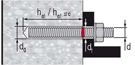
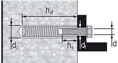
5 ESR-574 Most Widely Accepted and Trusted Page 5 of DEFORMED REINFORCMENT THREADED ROD h h HILTI HIS-N AND HIS-RN THREADED INSERTS h FIGURE INSTALLATION PARAMETERS
 ASTM F568M Class 5.8 M5 ( / 4 in.) to M4 ( in.) (equivalent to ISO 898-) ISO 898-4 Class 5.8 ISO 898-4 Class 8.8 ASTM F59 5 CW (6) / 4 -in. to 5 / 8 -in. ASTM F59 5 CW (6) / 4 -in. to / -in.")
6 ESR-574 Most Widely Accepted and Trusted Page 6 of FIGURE FLOWCHART FOR ESTABLISHMENT OF DESIGN BOND STRENGTH THREADED ROD SPECIFICATION CARBON STEEL STAINLESS STEEL ASTM A9 Grade B7 / in. ( 64 mm) ASTM F568M Class 5.8 M5 ( / 4 in.) to M4 ( in.) (equivalent to ISO 898-) ISO Class 5.8 ISO Class 8.8 ASTM F59 5 CW (6) / 4 -in. to 5 / 8 -in. ASTM F59 5 CW (6) / 4 -in. to / -in. ISO A4-70 M8 M4 ISO A4-50 M7 M0 TABLE SPECIFICATIONS AND PHYSICAL PROPERTIES OF COMMON CARBON AND STAINLESS STEEL THREADED ROD MATERIALS Minimum specified ultimate, f uta Minimum specified yield 0. percent offset, f ya psi 5,000 05,000 (MPa) (86) (74) f uta /f ya Elongation, min. percent 7 Reduction of Area, min. percent Specification for nuts ASTM A56 Grade DH psi 7,500 58, ASTM A56 Grade DH 9 (MPa) (500) (400) DIN 94 (8-AK) MPa (psi) (7,500) (58,000).5 - DIN 94 Grade 6 MPa (psi) (6,000) (9,800).5 5 DIN 94 Grade 8 psi 00,000 65,000 (MPa) (689) (448) ASTM F594 psi 85,000 45,000 (MPa) (586) (0) ASTM F594 MPa (psi) (0,500) (65,50) ISO 40 MPa (psi) (7,500) (0,450) ISO 40 Hilti HIT-HY 00 adhesive may be used in conjunction with all grades of continuously threaded carbon or stainless steel rod (all-thread) that comply with the code reference standards and that have thread characteristics comparable with ANSI B. UNC Coarse Thread Series or ANSI B.M M Profile Metric Thread Series. Values for threaded rod types and associated nuts supplied by Hilti are provided here. Standard Specification for Alloy-Steel and Stainless Steel Bolting Materials for High-Temperature Service Standard Specification for Carbon and Alloy Steel Externally Threaded Metric Fasteners 4 Mechanical properties of fasteners made of carbon steel and alloy steel Part : Bolts, screws and studs 5 Standard Steel Specification for Stainless Steel Bolts, Hex Cap Screws, and Studs 6 Mechanical properties of corrosion-resistant stainless steel fasteners Part : Bolts, screws and studs 7 Based on -in. (50 mm) gauge length except for A9, which are based on a gauge length of 4d and ISO 898, which is based on 5d. 8 Nuts of other grades and styles having specified proof load stresses greater than the specified grade and style are also suitable. Nuts must have specified proof load stresses equal to or greater than the minimum tensile of the specified threaded rod. 9 Nuts for fractional rods
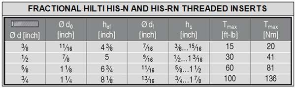
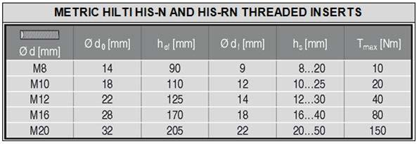
7 ESR-574 Most Widely Accepted and Trusted Page 7 of TABLE SPECIFICATIONS AND PHYSICAL PROPERTIES OF FRACTIONAL AND METRIC HIS-N AND HIS-RN INSERTS HILTI HIS-N AND HIS-RN INSERTS Minimum specified ultimate, f uta Minimum specified yield, f ya Carbon Steel DIN EN 077- SMnPb0+c or DIN 56 9SMnPb8K / 8 -in. and M8 to M0 Carbon Steel DIN EN 077- SMnPb0+c or DIN 56 9SMnPb8K / to / 4 -in. and M to M0 Stainless Steel EN X5CrNiMo 7-- psi 7,050 59,450 (MPa) (490) (40) psi 66,700 54,75 (MPa) (460) (75) psi 0,500 50,750 (MPa) (700) (50) BOLT, CAP SCREW OR STUD SPECIFICATION SAE J49 Grade 5 ASTM A5 4 / to -in. ASTM A9 5 Grade B8M (AISI 6) for use with HIS-RN ASTM A9 5 Grade B8T (AISI ) for use with HIS-RN TABLE 4 SPECIFICATIONS AND PHYSICAL PROPERTIES OF COMMON BOLTS, CAP SCREWS AND STUDS FOR USE WITH HIS-N AND HIS-RN INSERTS, Minimum specified ultimate f uta Minimum specified yield 0. percent offset f ya psi 0,000 9,000 (MPa) (88) (64) psi 0,000 9,000 (MPa) (88) (64) psi 0,000 95,000 (MPa) (759) (655) psi 5,000 00,000 (MPa) (86) (690) f uta /f ya Elongation, min. Reduction of Area, min. Specification for nuts SAE J A56 C, C, D, DH, DH Heavy Hex ASTM F ASTM F594 7 Minimum Grade 5 bolts, cap screws or studs must be used with carbon steel HIS-N inserts. Only stainless steel bolts, cap screws or studs must be used with HIS-RN inserts. Mechanical and Material Requirements for Externally Threaded Fasteners 4 Standard Specification for Structural Bolts, Steel, Heat Treated, 0/05 ksi Minimum Tensile Strength 5 Standard Specification for Alloy-Steel and Stainless Steel Bolting Materials for High-Temperature Service 6 Nuts must have specified minimum proof load stress equal to or greater than the specified minimum full-size tensile of the specified stud. 7 Nuts for stainless steel studs must be of the same alloy group as the specified bolt, cap screw, or stud. TABLE 5 SPECIFICATIONS AND PHYSICAL PROPERTIES OF COMMON STEEL REINFORCING BARS REINFORCING BAR SPECIFICATION Minimum specified ultimate, f uta Minimum specified yield, f ya psi 90,000 60,000 ASTM A65 Gr. 60 (MPa) (60) (44) psi 60,000 40,000 ASTM A65 Gr. 40 (MPa) (44) (76) psi 80,000 60,000 ASTM A706 Gr. 60 (MPa) (550) (44) MPa DIN 488 BSt 500 (psi) (79,750) (7,500) MPa CAN/CSA-G0.8 4 Gr. 400 (psi) (78,00) (58,000) Standard Specification for Deformed and Plain Carbon Steel Bars for Concrete Reinforcement Standard Specification for Low Alloy Steel Deformed and Plain Bars for Concrete Reinforcement Reinforcing steel; reinforcing steel bars; dimensions and masses 4 Billet-Steel Bars for Concrete Reinforcement
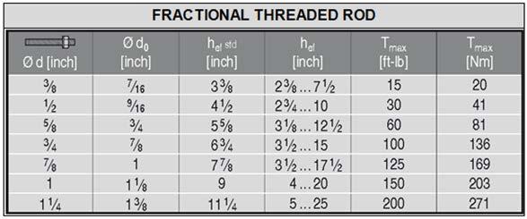
8 ESR-574 Most Widely Accepted and Trusted Page 8 of Fractional Threaded Rod and Reinforcing Bars Steel Strength ISO 898- Class 5.8 TABLE 6 STEEL DESIGN INFORMATION FOR FRACTIONAL THREADED ROD AND REINFORCING BARS Nominal rod diameter (in.) / 8 / / 8 / 4 / 8 / 4 Rod O.D. d in (mm) (9.5) (.7) (5.9) (9.) (.) (5.4) (.8) Rod effective cross-sectional area A se in (mm ) (50) (9) (46) (6) (98) (9) (65) lb 5,60 0,90 6,85 4,50,470 4,90 70,60 Nominal as governed by steel (kn) (5.0) (45.8) (7.9) (07.9) (48.9) (95.) (.5) ASTM A9 B7 ASTM F59, CW Stainless lb,80 6,75 9,80 4,550 0,085 6,45 4,55 (kn) (.5) (7.5) (4.7) (64.7) (89.) (7.) (87.5) Strength reduction factor for tension Strength reduction factor for shear lb 9,685 7,75 8,50 4,80 57,70 75,70,5 Nominal as governed by steel (kn) (4.) (78.9) (5.7) (86.0) (56.7) (6.8) (58.8) lb 4,845 0,640 6,950 5,085 4,65 45,45 7,680 (kn) (.5) (47.) (75.4) (.6) (54.0) (0.) (.) Strength reduction factor for tension Strength reduction factor for shear lb 7,750 4,90,600 8,40 9,45 5,485 8,70 Nominal as governed by steel (kn) (4.5) (6.) (00.5) (6.5) (74.6) (9.0) (66.4) lb,875 8,55,560 7,060,545 0,890 49,45 (kn) (7.) (7.9) (60.) (75.9) (04.7) (7.4) (9.8) Strength reduction factor for tension Strength reduction factor for shear Nominal Reinforcing bar size (Rebar) # #4 #5 #6 #7 #8 #9 #0 Nominal bar diameter d in. / 8 / / 8 / 4 / 8 / 8 / 4 (mm) (9.5) (.7) (5.9) (9.) (.) (5.4) (8.6) (.8) Bar effective cross-sectional area A se in (mm ) (7) (9) (00) (84) (87) (50) (645) (89) lb 6,600,000 8,600 6,400 6,000 47,400 60,000 76,00 Nominal as governed by steel (kn) (9.4) (5.4) (8.7) (7.4) (60.) (0.9) (66.9) (9.0) lb,960 7,00,60 5,840,600 8,440 6,000 45,70 (kn) (7.6) (.0) (49.6) (70.5) (96.) (6.5) (60.) (0.4) Strength reduction factor for tension Strength reduction factor for shear lb 9,900 8,000 7,900 9,600 54,000 7,00 90,000 4,00 Nominal as governed by steel (kn) (44.0) (80.) (4.) (76.) (40.) (6.) (400.4) (508.5) ASTM A65 Grade 40 ASTM A65 Grade 60 ASTM A706 Grade 60 lb 5,940 0,800 6,740,760,400 4,660 54,000 68,580 (kn) (6.4) (48.0) (74.5) (05.7) (44.) (89.8) (40.) (05.) Strength reduction factor for tension Strength reduction factor for shear lb 8,800 6,000 4,800 5,00 48,000 6,00 80,000 0,600 Nominal as governed by steel (kn) (9.) (7.) (0.) (56.6) (.5) (8.) (55.9) (45.0) lb 5,80 9,600 4,880,0 8,800 7,90 48,000 60,960 (kn) (.5) (4.7) (66.) (94.0) (8.) (68.7) (.5) (7.) Strength reduction factor for tension 0.75 Strength reduction factor for shear 0.65 For SI: inch = 5.4 mm, lbf = N. For pound-inch units: mm = inches, N = 0.48 lbf Values provided for common rod material types are based on specified s and calculated in accordance with ACI 8- Eq. (D-) and Eq. (D-9). Nuts and washers must be appropriate for the rod. For use with the load combinations of IBC Section 605. or ACI 8 Section 9., as set forth in ACI 8 D.4.. If the load combinations of ACI 8 Appendix C are used, the appropriate value of must be determined in accordance with ACI 8 D.4.4. Values correspond to a brittle steel element. For use with the load combinations of IBC Section 605. or ACI 8 Section 9., as set forth in ACI 8 D.4.. If the load combinations of ACI 8 Appendix C are used, the appropriate value of must be determined in accordance with ACI 8 D.4.4. Values correspond to a ductile steel element.
9 ESR-574 Most Widely Accepted and Trusted Page 9 of Fractional Threaded Rod and Reinforcing Bars Concrete Breakout Strength Carbide Bit TABLE 7 CONCRETE BREAKOUT DESIGN INFORMATION FOR FRACTIONAL THREADED ROD AND REINFORCING BARS IN HOLES DRILLED WITH A HAMMER DRILL AND CARBIDE BIT Effectiveness factor for uncracked concrete Nominal rod diameter (in.) / Reinforcing bar size / 8 or # / or #4 5 / / 8 or #5 4 or 7 / #6 8 or #7 in-lb 4 k c,uncr (SI) (0) in. / 8 / 4 / 8 / / 4 4 / 5 Minimum Embedment h ef,min (mm) (60) (70) (79) (89) (89) (0) (4) (7) in. 7 / 0 / 5 7 / 0 / 5 Maximum Embedment h ef,max (mm) (9) (54) (8) (8) (445) (508) (57) (65) or #8 #9 / 4 or #0 Min. anchor spacing 4 s min in. 7 / 8 / / 8 / 4 4 / / 8 6 / 4 (mm) (48) (64) (79) (95) () (7) (4) (59) Min. edge distance 4 c min - 5d; or see Section 4..9 of this report for design with reduced minimum edge distances Minimum concrete thickness h min in. h ef + / 4 (mm) (h ef + 0) () h ef + d 0 Critical edge distance splitting c ac - See Section 4..0 of this report. (for uncracked concrete) Strength reduction factor for tension, concrete failure modes, Condition B Strength reduction factor for shear, concrete failure modes, Condition B For SI: inch 5.4 mm, lbf = N, psi = MPa. For pound-inch units: mm = inches, N = 0.48 lbf, MPa = 45.0 psi. For additional setting information, see installation instructions in Figure 5. Values provided for post-installed anchors with category as determined from ACI 55.4 given for Condition B. Condition B applies without supplementary reinforcement or where pullout (bond) or pryout govern, as set forth in ACI 8 D.4., while condition A requires supplemental reinforcement. Values are for use with the load combinations of IBC Section 605. or ACI 8 Section 9. as set forth in ACI 8 D.4.. If the load combinations of ACI 8 Appendix Care used, the appropriate value of must be determined in accordance with ACI 8 D.4.4. d 0 = hole diameter. 4 For installations with / 4 -inch edge distance, refer to Section 4..9 for spacing and maximum torque requirements.
10 ESR-574 Most Widely Accepted and Trusted Page 0 of Fractional Threaded Rod and Reinforcing Bars Bond Strength Carbide Bit TABLE 8 BOND STRENGTH DESIGN INFORMATION FOR FRACTIONAL THREADED ROD AND REINFORCING BARS IN HOLES DRILLED WITH A HAMMER DRILL AND CARBIDE BIT / 8 / Nominal rod diameter (in.) 5 / 8 / 4 7 / 8 / 4 Temperature Range A B C Minimum anchor embedment depth Maximum anchor embedment depth psi,50,60,690,700,50,90,50 (MPa) (0.5) (.) (.7) (.7) (0.4) (9.6) (7.9) psi,40,480,455,80,0,0 880 (MPa) (9.7) (0.) (0.0) (9.5) (8.4) (7.7) (6.) psi (MPa) (5.6) (5.4) (5.4) (5.6) (4.8) (4.6) (.5) in. / 8 / 4 / 8 / / 4 5 h ef,min (mm) (60) (70) (80) (89) (89) (0) (7) in. 7 / 0 / 5 7 / 0 5 h ef,max (mm) (9) (54) (8) (8) (445) (508) (65) Permissible Installation Conditions Dry concrete Anchor - Category d Anchor Water-saturated - concrete Category ws Nominal Reinforcing bar size (Rebar) # #4 #5 #6 #7 #8 #9 #0 psi,0 A k,uncr (MPa) (8.4) psi,00 B k,uncr (MPa) (7.0) psi 590 C k,uncr (MPa) (4.) Minimum anchor embedment in. / 8 / 4 / 8 / / 4 4 / 5 h depth ef,min (mm) (60) (70) (79) (89) (89) (0) (4) (7) Maximum anchor embedment in. 7 / 0 / 5 7 / 0 / 5 h depth ef,max (mm) (9) (54) (8) (8) (445) (508) (57) (65) Temperature Range Permissible Installation Conditions Dry concrete & Water-saturated concrete Anchor Category - d & ws For SI: inch 5.4 mm, lbf = N, psi = MPa. For pound-inch units: mm = inches, N = 0.48 lbf, MPa = 45.0 psi. Bond values correspond to concrete compressive range,500 psi f c 4,500 psi. For 4,500 psi < f c 6,500 psi, tabulated characteristic bond s may be increased by 6 percent. For 6,500 psi < f c 8,000 psi, tabulated characteristic bond s may be increased by 0 percent. Temperature range A: Maximum short term temperature = 04 F (40 C), maximum long term temperature = 75 F (4 C). Temperature range B: Maximum short term temperature = 76 F (80 C), maximum long term temperature = F (50 C). Temperature range C: Maximum short term temperature = 48 F (0 C), maximum long term temperature = 6 F (7 C). Short term elevated concrete temperatures are those that occur over brief intervals, e.g., as a result of diurnal cycling. Long term concrete temperatures are roughly constant over significant periods of time.
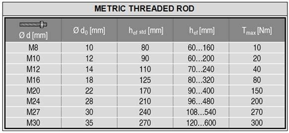
11 ESR-574 Most Widely Accepted and Trusted Page of Metric Threaded Rod and EU Metric Reinforcing Bars Steel Strength ISO 898- Class 5.8 ISO 898- Class 8.8 ISO 506- Class A4 Stainless DIN 488 BSt 550/500 TABLE 9 STEEL DESIGN INFORMATION FOR METRIC THREADED ROD AND EU METRIC REINFORCING BARS Nominal rod diameter (mm) Rod Outside Diameter d mm (in.) (0.) (0.9) (0.47) (0.6) (0.79) (0.94) (.06) (.8) Rod effective cross-sectional area A se mm (in. ) (0.057) (0.090) (0.) (0.4) (0.80) (0.547) (0.7) (0.870) kn Nominal as governed by (lb) (4,5) (6,59) (9,476) (7,647) (7,59) (9,679) (5,594) (6,059) steel kn (lb) (,060) (,60) (5,685) (0,588) (6,5) (,807) (0,956) (7,85) Strength reduction factor for tension Strength reduction factor for shear kn Nominal as governed by (lb) (6,580) (0,4) (5,6) (8,6) (44,06) (6,486) (8,550) (00,894) steel kn (lb) (,90) (5,6) (9,097) (6,94) (6,48) (8,09) (49,50) (60,57) Strength reduction factor for tension Strength reduction factor for shear kn Nominal as governed by (lb) (5,760) (9,7) (,66) (4,706) (8,555) (55,550) (4,5) (50,5) steel kn (lb) (,880) (4,564) (7,960) (4,84) (,) (,0) (4,680) (0,00) Strength reduction factor for tension Strength reduction factor for shear Reinforcing bar size Nominal bar diameter d mm (in.) (0.5) (0.94) (0.47) (0.55) (0.60) (0.787) (0.984) (.0) (.60) Bar effective cross-sectional area A se mm (in. ) (0.078) (0.) (0.75) (0.9) (0.) (0.487) (0.76) (0.954) (.47) kn Nominal as governed by (lb) (6,5) (9,7) (,984) (9,04) (4,860) (8,844) (60,694) (76,5) (99,44) steel kn (lb) (,70) (5,87) (8,90) (,40) (4,96) (,07) (6,46) (45,68) (59,665) Strength reduction factor for tension Strength reduction factor for shear For SI: inch 5.4 mm, lbf = N, psi = MPa. For pound-inch units: mm = inches, N = 0.48 lbf, MPa = 45.0 psi Values provided for common rod material types are based on specified s and calculated in accordance with ACI 8- Eq. (D-) and Eq. (D-9). Nuts and washers must be appropriate for the rod. For use with the load combinations of IBC Section 605. or ACI 8 Section 9., as set forth in ACI 8 D.4.. If the load combinations of ACI 8 Appendix C are used, the appropriate value of must be determined in accordance with ACI 8 D.4.4. Values correspond to a brittle steel element. A4-70 Stainless (M8- M4); A4-50 Stainless (M7- M0)
12 ESR-574 Most Widely Accepted and Trusted Page of Metric Threaded Rod and EU Metric Reinforcing Bars Concrete Breakout Strength Carbide Bit TABLE 0 CONCRETE BREAKOUT DESIGN INFORMATION FOR METRIC THREADED ROD AND EU METRIC REINFORCING BARS IN HOLES DRILLED WITH A HAMMER DRILL AND CARBIDE BIT Minimum Embedment Maximum Embedment Min. anchor spacing 4 h ef,min h ef,max s min Nominal rod diameter (mm) mm (in.) (.4) (.4) (.8) (.) (.5) (.8) (4.) (4.7) mm (in.) (6.) (7.9) (9.4) (.6) (5.7) (8.9) (.) (.6) mm (in.) (.6) (.0) (.4) (.) (.9) (4.7) (5.) (5.9) Min. edge distance 4 c min - 5d; or see Section 4..9 of this report for design with reduced minimum edge distances Minimum concrete thickness h min mm h ef + 0 () h ef + d o (in.) (h ef + / 4 ) Reinforcing bar size Minimum Embedment Maximum Embedment Min. anchor spacing 4 h ef,min h ef,max s min mm (in.) (.4) (.4) (.8) (.0) (.) (.5) (.9) (4.4) (5.0) mm (in.) (6.) (7.9) (9.4) (.0) (.6) (5.7) (9.7) (.0) (5.) mm (in.) (.6) (.0) (.4) (.) (.9) (4.7) (5.) (5.5) (6.) Min. edge distance 4 c min - 5d; or see Section 4..9 of this report for design with reduced minimum edge distances Minimum concrete thickness Critical edge distance splitting (for uncracked concrete) Effectiveness factor for uncracked concrete h min mm h ef + 0 (in.) (h ef + / 4 ) h ef + d o () c ac - See Section 4..0 of this report. SI 0 k c,uncr (in-lb) (4) Strength reduction factor for tension, concrete failure modes, Condition B Strength reduction factor for shear, concrete failure modes, Condition B For SI: inch 5.4 mm, lbf = N, psi = MPa For pound-inch units: mm = inches, N = 0.48 lbf, MPa = 45.0 psi. For additional setting information, see installation instructions in Figure 5. Values provided for post-installed anchors with category as determined from ACI 55.4 given for Condition B. Condition B applies without supplementary reinforcement or where pullout (bond) or pryout govern, as set forth in ACI 8 D.4., while condition A requires supplemental reinforcement. Values are for use with the load combinations of IBC Section 605. or ACI 8 Section 9. as set forth in ACI 8 D.4.. If the load combinations of ACI 8 Appendix C are used, the appropriate value of must be determined in accordance with ACI 8 D.4.4. d 0 = drill bit diameter. 4 For installations with / 4 -inch edge distance, refer to Section 4..9 for spacing and maximum torque requirements.
13 ESR-574 Most Widely Accepted and Trusted Page of Metric Threaded Rod and EU Reinforcing Bars Bond Strength Carbide Bit Temperature Range TABLE BOND STRENGTH DESIGN INFORMATION FOR METRIC THREADED ROD AND EU REINFORCING BARS IN HOLES DRILLED WITH A HAMMER DRILL AND CARBIDE BIT Nominal rod diameter (mm) MPa A k,uncr (psi) (,50) (,50) (,60) (,690) (,700) (,50) (,90) (,50) B C Minimum anchor embedment depth Maximum anchor embedment depth MPa (psi) (,40) (,40) (,480) (,455) (,80) (,0) (,0) (880) MPa (psi) (805) (805) (790) (790) (805) (690) (660) (50) mm h ef,min (in.) (.4) (.4) (.8) (.) (.5) (.8) (4.) (4.7) mm h ef,max (in.) (6.) (7.9) (9.4) (.6) (5.7) (8.9) (.) (.6) Permissible Installation Conditions Temperature Range Dry concrete Water-saturated concrete DESIGN INFORMATION A B C Minimum anchor embedment depth Maximum anchor embedment depth Anchor - Category d Anchor Category - ws SYMBOL UNITS Nominal Reinforcing bar size (Rebar) h ef,min h ef,max MPa 8.4 (psi) (,0) MPa 7.0 (psi) (,00) MPa 4. (psi) (590) mm (in.) (.4) (.4) (.8) (.0) (.) (.5) (.9) (4.4) (5.0) mm (in.) (6.) (7.9) (9.4) (.0) (.6) (5.7) (9.7) (.0) (5.) Permissible Installation Conditions Dry concrete & Water-saturated concrete Anchor Category - d & ws For SI: inch 5.4 mm, lbf = N, psi = MPa. For pound-inch units: mm = inches, N = 0.48 lbf, MPa = 45.0 psi. Bond values correspond to concrete compressive range,500 psi f c 4,500 psi. For 4,500 psi < f c 6,500 psi, tabulated characteristic bond s may be increased by 6 percent. For 6,500 psi < f c 8,000 psi, tabulated characteristic bond s may be increased by 0 percent. Temperature range A: Maximum short term temperature = 04 F (40 C), maximum long term temperature = 75 F (4 C). Temperature range B: Maximum short term temperature = 76 F (80 C), maximum long term temperature = F (50 C). Temperature range C: Maximum short term temperature = 48 F (0 C), maximum long term temperature = 6 F (7 C). Short term elevated concrete temperatures are those that occur over brief intervals, e.g., as a result of diurnal cycling. Long term concrete temperatures are roughly constant over significant periods of time.
14 ESR-574 Most Widely Accepted and Trusted Page 4 of Canadian Reinforcing Bars Steel Strength TABLE STEEL DESIGN INFORMATION FOR CANADIAN METRIC REINFORCING BARS Bar size 0 M 5 M 0 M 5 M 0 M Nominal bar diameter d mm (in.) (0.445) (0.60) (0.768) (0.99) (.77) Bar effective cross-sectional area A se mm (in. ) (0.55) (0.) (0.46) (0.77) (.088) CSA G0 Nominal as governed by steel kn (lb) (,75) (4,408) (6,55) (60,548) (85,9) kn (lb) (7,05) (4,645) (,755) (6,0) (5,45) Strength reduction factor for tension Strength reduction factor for shear For SI: inch 5.4 mm, lbf = N, psi = MPa. For pound-inch units: mm = inches, N = 0.48 lbf, MPa = 45.0 psi Values provided for common rod material types based on specified s and calculated in accordance with ACI 8- Eq. (D-) and Eq. (D-9). Other material specifications are admissible. For use with the load combinations of ACI 8 Section 9., as set forth in ACI 8 Section D.4.. Canadian Reinforcing Bars Concrete Breakout Strength Carbide Bit TABLE CONCRETE BREAKOUT DESIGN INFORMATION FOR CANADIAN METRIC REINFORCING BARS IN HOLES DRILLED WITH A HAMMER DRILL AND CARBIDE BIT Bar size 0 M 5 M 0 M 5 M 0 M Effectiveness factor for uncracked SI 0 k concrete c,uncr (in-lb) (4) Minimum Embedment h ef,min mm (in.) (.8) (.) (.5) (4.0) (4.7) Maximum Embedment h ef,max mm (in.) (8.9) (.6) (5.4) (9.8) (.5) Min. bar spacing s min mm (in.) (.) (.) (.8) (5.0) (5.9) Min. edge distance c min mm 5d; or see Section 4..9 of this report for design with reduced minimum (in.) edge distances Minimum concrete thickness h min mm (in.) h ef + 0 (h ef + / 4 ) (4) h ef + d o Critical edge distance splitting (for uncracked concrete) c ac - See Section 4..0 of this report. Strength reduction factor for tension, concrete failure modes, Condition B Strength reduction factor for shear, concrete failure modes, Condition B For SI: inch 5.4 mm, lbf = N, psi = MPa. For pound-inch units: mm = inches, N = 0.48 lbf, MPa = 45.0 psi Additional setting information is described in Figure 5, Manufacturers Printed Installation Instructions (MPII). Values provided for post-installed anchors installed under Condition B without supplementary reinforcement. For installations with / 4 -inch edge distance, refer to Section 4..9 for spacing and maximum torque requirements. 4 d 0 = hole diameter.
15 ESR-574 Most Widely Accepted and Trusted Page 5 of Canadian Reinforcing Bars Bond Strength Carbide Bit Temperature Range TABLE 4 BOND STRENGTH DESIGN INFORMATION FOR CANADIAN METRIC REINFORCING BARS IN HOLES DRILLED WITH A HAMMER DRILL AND CARBIDE BIT Bar Size 0 M 5 M 0 M 5 M 0 M MPa 8.4 A k,uncr (psi) (,0) B C Minimum anchor embedment depth Maximum anchor embedment depth MPa 7.0 (psi) (,00) MPa 4. (psi) (590) mm h ef,min (in.) (.8) (.) (.5) (4.0) (4.7) mm h ef,max (in.) (8.9) (.6) (5.4) (9.8) (.5) Permissible Installation Conditions Dry concrete & Water-saturated concrete Anchor - Category d & ws For SI: inch 5.4 mm, lbf = N, psi = MPa. For pound-inch units: mm = inches, N = 0.48 lbf, MPa = 45.0 psi Bond values correspond to concrete compressive in the range,500 psi f c 4,500 psi. For the range 4,500 psi < f c 6,500 psi, tabulated characteristic bond s may be increased by 6 percent. For the range 6,500 psi < f c 8,000 psi, tabulated characteristic bond s may be increased by 0 percent. Temperature range A: Maximum short term temperature = 04 F (40 C), Maximum long term temperature = 75 F (4 C). Temperature range B: Maximum short term temperature = 76 F (80 C), Maximum long term temperature = F (50 C). Temperature range C: Maximum short term temperature = 48 F (0 C), Maximum long term temperature = 6 F (7 C). Short term elevated concrete temperatures are those that occur over brief intervals, e.g., as a result of diurnal cycling. Long term concrete temperatures are roughly constant over significant periods of time.
16 ESR-574 Most Widely Accepted and Trusted Page 6 of Fractional and Metric HIS-N and HIS-RN Internal Threaded Insert Steel Strength TABLE 5 STEEL DESIGN INFORMATION FOR FRACTIONAL AND METRIC HIS-N AND HIS-RN THREADED INSERTS DESIGN INFORMATION Symbol Units Nominal Bolt/Cap Screw Diameter (in.) Fractional / 8 / 5 / 8 Units Nominal Bolt/Cap Screw Diameter (mm) Metric / HIS Insert O.D. HIS insert length Bolt effective crosssectional area HIS insert effective cross-sectional area ASTM A9 B7 ASTM A9 Grade B8M SS ISO 898- Class 8.8 ISO 506- Class A4-70 Stainless Nominal steel ASTM A9 B7 bolt/cap screw Nominal steel HIS-N insert Nominal steel ASTM A9 Grade B8M SS bolt/cap screw Nominal steel HIS-RN insert Nominal steel ISO 898- Class 8.8 bolt/cap screw Nominal steel HIS-N insert Nominal steel ISO 506- Class A4-70 Stainless bolt/cap screw Nominal steel HIS-RN insert D l A se A insert in mm (mm) (6.5) (0.5) (5.4) (7.6) (in.) (0.49) (0.65) (0.8) (.00) (.09) in mm (mm) (0) (5) (70) (05) (in.) (.54) (4.) (4.9) (6.69) (8.07) in mm (mm ) (50) (9) (46) (6) (in. ) (0.057) (0.090) (0.) (0.4) (0.80) in mm (mm ) (5) (57) (60) (65) (in. ) (0.080) (0.67) (0.6) (0.97) (0.68) lb 9,690 7,740 8,50 4,85 kn (kn) (4.) (78.9) (5.7) (86.0) (lb) lb 5,85 0,645 6,950 5,090 kn (kn) (5.9) (47.) (75.4) (.6) (lb) lb,650 6,95 6,95 7,60 kn (kn) (56.) (7.0) (9.8) (.7) (lb) lb 8,55 5,60 4,860 6,795 kn (kn) (7.9) (69.4) (0.6) (6.7) (lb) lb 5,5 9,65 4,95,075 kn (kn) (.8) (4.7) (66.) (98.) (lb) lb 7,65,40 8,955 9,55 kn (kn) (76.) (04.) (7.) (75.9) (lb) lb kn (kn) (lb) (6,580) (0,40) (5,60) (8,5) (44,065) lb kn (kn) (lb) (,950) (6,60) (9,00) (6,940) (6,440) lb kn (kn) (lb) (5,669) (,894) (7,488) (6,48) (4,57) lb kn (kn) (lb) (5,760) (9,7) (,66) (4,706) (8,555) lb kn (kn) (lb) (,456) (5,476) (7,960) (4,84) (,) lb kn (kn) (lb) (8,099) (6,99) (6,6) (40,00) (7,94) Strength reduction factor for tension Strength reduction factor for shear For SI: inch 5.4 mm, lbf = N, psi = MPa. For pound-inch units: mm = inches, N = 0.48 lbf, MPa = 45.0 psi Values provided for common rod material types based on specified s and calculated in accordance with ACI 8- Eq. (D-) and Eq. (D-9). Nuts and washers must be appropriate for the rod. For use with the load combinations of ACI 8 9., as set forth in ACI 8 D.4.. Values correspond to a brittle steel element for the HIS insert. For the calculation of the design steel in tension and shear for the bolt or screw, the factor for ductile steel failure according to ACI 8 D4. can be used.
17 ESR-574 Most Widely Accepted and Trusted Page 7 of Fractional and Metric HIS-N and HIS-RN Internal Threaded Insert Concrete Breakout Strength Carbide Bit TABLE 6 CONCRETE BREAKOUT DESIGN INFORMATION FOR FRACTIONAL AND METRIC HILTI HIS-N AND HIS-RN INSERTS IN HOLES DRILLED WITH A HAMMER DRILL AND CARBIDE BIT DESIGN INFORMATION Symbol Units Nominal Bolt/Cap Screw Diameter (in.) Fractional / 8 / 5 / 8 Units Nominal Bolt/Cap Screw Diameter (mm) Metric / Effectiveness factor for uncracked concrete in-lb 4 SI 0 k c,uncr (SI) (0) (in-lb) (4) Effective embedment depth Min. anchor spacing Min. edge distance h ef s min c min in. 4 / / 4 8 / 8 mm (mm) (0) (5) (70) (05) (in.) (.5) (4.) (4.9) (6.7) (8.) in. / / mm (mm) (8) (0) (7) (40) (in.) (.5) (.5) (4.0) (5.0) (5.5) in. / / mm (mm) (8) (0) (7) (40) (in.) (.5) (.5) (4.0) (5.0) (5.5) Minimum concrete thickness h min in mm (mm) (50) (70) (0) (70) (in.) (4.7) (5.9) (6.7) (9.) (0.6) Critical edge distance splitting c ac - See Section 4..0 of this report - See Section 4..0 of this report (for uncracked concrete) Strength reduction factor for tension, concrete failure modes, Condition B Strength reduction factor for shear, concrete failure modes, Condition B For SI: inch 5.4 mm, lbf = N, psi = MPa. For pound-inch units: mm = inches, N = 0.48 lbf, MPa = 45.0 psi Additional setting information is described in Figure 5, Manufacturers Printed Installation Instructions (MPII). Values provided for post-installed anchors installed under Condition B without supplementary reinforcement as defined in ACI 8 D.4.. For installations with / 4 -inch edge distance, refer to Section 4..9 for spacing and maximum torque requirements.

18 ESR-574 Most Widely Accepted and Trusted Page 8 of Fractional and Metric HIS-N and HIS-RN Internal Threaded Insert Bond Strength Carbide Bit TABLE 7 BOND STRENGTH DESIGN INFORMATION FOR FRACTIONAL AND METRIC HILTI HIS-N AND HIS-RN INSERTS IN HOLES DRILLED WITH A HAMMER DRILL AND CARBIDE BIT DESIGN INFORMATION Symbol Units Nominal Bolt/Cap Screw Diameter (in.) Fractional / 8 / 5 / 8 Units Nominal Bolt/Cap Screw Diameter (mm) Metric / Effective embedment depth HIS Insert O.D. h ef D in. 4 / / 4 8 / 8 mm (mm) (0) (5) (70) (05) (in.) (.5) (4.) (4.9) (6.7) (8.) in mm (mm) (6.5) (0.5) (5.4) (7.6) (in.) (0.49) (0.65) (0.8) (.00) (.09) Temperature range A B C Characteristic bond Characteristic bond Characteristic bond psi,505,90,80,5 MPa (MPa) (0.4) (9.6) (8.) (7.7) (psi) (,505) (,505) (,90) (,80) (,5) psi,05, MPa (MPa) (8.) (7.5) (6.4) (5.8) (psi) (,05) (,05) (,085) (90) (840) psi MPa (MPa) (4.) (4.) (.7) (.) (psi) (60) (60) (595) (55) (475) Permissible installation conditions Dry concrete Water saturated concrete Anchor Category - - d Anchor Category - - ws For SI: inch 5.4 mm, lbf = N, psi = MPa. For pound-inch units: mm = inches, N = 0.48 lbf, MPa = 45.0 psi Bond values correspond to concrete compressive in the range,500 psi f c 4,500 psi. For the range 4,500 psi < f c 6,500 psi, tabulated characteristic bond s may be increased by 6 percent. For the range 6,500 psi < f c 8,000 psi, tabulated characteristic bond s may be increased by 0 percent. Temperature range A: Maximum short term temperature = 04 F (40 C), Maximum long term temperature = 75 F (4 C). Temperature range B: Maximum short term temperature = 76 F (80 C), Maximum long term temperature = F (50 C). Temperature range C: Maximum short term temperature = 48 F (0 C), Maximum long term temperature = 6 F (7 C). Short term elevated concrete temperatures are those that occur over brief intervals, e.g., as a result of diurnal cycling. Long term concrete temperatures are roughly constant over significant periods of time. FIGURE HILTI HIT-HY 00 ANCHORING SYSTEM AND ANCHOR ELEMENTS
 base material temperature < 04 F. Assume maximum long term base material temperature < 75 F.")
19 ESR-574 Most Widely Accepted and Trusted Page 9 of Specifications / Assumptions: ASTM A9 Grade B7 threaded rod Normal weight concrete, f c = 4,000 psi Seismic Design Category (SDC) B No supplementary reinforcing in accordance with ACI 8- D. will be provided. Assume maximum short term (diurnal) base material temperature < 04 F. Assume maximum long term base material temperature < 75 F. Assume installation in dry concrete and hammerdrilled holes. Assume concrete will remain uncracked for service life of anchorage. Dimensional Parameters: h ef s c a,min h d = 9.0 in. = 4.0 in. =.5 in. =.0 in. = / in. Calculation in accordance with ACI 8- Appendix D and this report for use with the 009 and 006 IBC Step. Check minimum edge distance, anchor spacing and member thickness: c min =.5 in. < c a,min =.5 in. OK s min =.5 in. s = 4.0 in. OK h min = h ef +.5 in. = = 0.5 in. h =.0 OK h ef,min h ef h ef,max =.75 in. 9 in. 0 in. OK Step. Check steel in tension: Single Anchor: = A se f uta = 0.49 in 5,000 psi = 7,78 lb. Anchor Group: = n A se f uta = ,78 lb. = 6,606 lb. Or using Table 6: = ,75 lb. = 6,60 lb. Step. Check concrete breakout in tension: ANc Ncbg ec,n ed,n c,n cp,n Nb A Nc0 ACI 8 Code Ref. - D.5.. Eq. (D-) D.5.. Eq. (D-4) A Nc = ( h ef + s)(.5 h ef + c a,min ) = ( 9 + 4)(.5 +.5) = 496 in - - A Nc0 = 9 h ef = 79 in D.5.. and Eq. (D-5) - ec,n =.0 no eccentricity of tension load with respect to tension-loaded anchors D Report Ref. ca,min.5 ed,n D.5..5 and Eq. (D-0) -.5h.5 9 ef Table 7 Table 8 Table Table 6 c,n =.0 uncracked concrete assumed (k c,uncr = 4) D.5..6 Table 7 - Determine c ac : From Table 8: uncr =,60 psi kc, uncr 4 uncr hef f ' c 9.0 4, 000,899 psi >,60 psi use,60 psi d 0.5 c ac h ef 0.4 uncr h, =. in.,60 hef, Section 4..0 Table 8 For c a,min < c ac max ca, min;.5 hef max.5;.5 9 cp,n 0.6 D.5..7 and Eq. (D-) - c. ac N b k.5.5 c, uncr f ' c hef 4.0 4,000 9 = 40,98 lb. D.5.. and Eq. (D-6) Table N cbg ,98,868 lb N cbg = 0.65,868 = 8,64 lb. D.4.(c) Table 7 FIGURE 4 SAMPLE CALCULATION
20 ESR-574 Most Widely Accepted and Trusted Page 0 of Step 4. Check bond in tension: ANa Nag ANa0 ec,na ed,na cp,na Nba D.5.5. Eq. (D-9) - A Na = (c Na + s)(c Na + c a,min ) c Na = uncr 0d a 0 0.5,00,60,00 A Na = ( )( ) = 7.7 in = 6.05 in. D.5.5. Eq. (D-) A Na0 = (c Na ) = ( 6.05) = 46.4 in D.5.5. and Eq. (D-0) - ec,na =.0 no eccentricity loading is concentric D Table 8 ca,min = 0.8 ed, Na cna 6.05 D max ca, min; cna max.5;6.05 cp, Na 0.7 D c. ac N ba = uncr d h ef =.0, =,76 lb. D.5.5. and Eq. (D-) Table N ag ,76 = 4,740 lb N ag = ,740 =,08 lb. D.4.(c) Table 8 Step 5. Determine controlling : Steel Strength = 6,60 lb. Concrete Breakout Strength N cbg = 8,64 lb. Bond Strength N ag =,08 lb. CONTROLS D.4. - FIGURE 4 SAMPLE CALCULATION (Continued)


21 ESR-574 Most Widely Accepted and Trusted Page of FIGURE 5 MANUFACTURER S PRINTED INSTALLATION INSTRUCTIONS (MPII)


")
22 ESR-574 Most Widely Accepted and Trusted Page of FIGURE 5 MANUFACTURER S PRINTED INSTALLATION INSTRUCTIONS (MPII) (Continued)


")
23 ESR-574 Most Widely Accepted and Trusted Page of FIGURE 5 MANUFACTURER S PRINTED INSTALLATION INSTRUCTIONS (MPII) (Continued)