Residual stresses in the martensitic part produced by Selective Laser Melting technology applied for the mould industry
|
|
|
- Tracy Richard
- 5 years ago
- Views:
Transcription


1 Residual stresses in the martensitic part produced by Selective Laser Melting technology applied for the mould industry 1 M. Averyanova, 1 Ph. Bertrand, 2 V.Ji, 3 B. Verquin, 1 ENISE, 2 ICMMO/LEMHE 3 CETIM, Contact: averyanova@enise.fr
2 Outline 1.Introduction 2.Results and discussion 3.Conclusions
3 Objective To analyze the effect of chemical composition of 17-4 PH martensitic stainless steel powder on residual macro-stresses formed during SLM process by X-ray diffraction sin 2 Ψ method
4 Selective laser melting. Process steps Powder material Laser parameters Equipement parameters Etc. Physical processes: Radiation Transfer (reflexion, absorption) Heat Transfer Fusion Solidification Evaporation Hydrodynamique (surface tension) Thermochemical (oxydation, atmosphere) Segregation (redistribution of components during solidification) Mechanical properties Microstructure Geometry Etc.


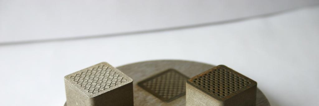
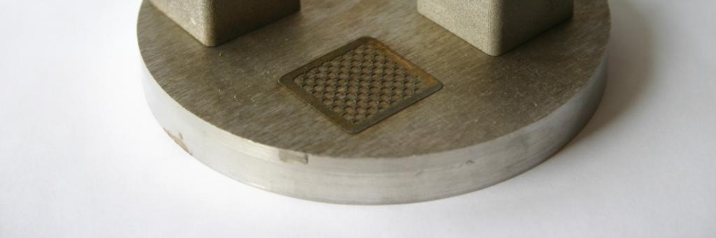
5 Application of Selective Laser Melting process Inox 904L Laser welding General view of the fabricated hip joint
6 2. Results and discussion: Powder material characterization. Process parameters. Final microstructure of 17-4 PH manufactured parts.
")

7 Particles dimension, size distribution and morphology of 17-4 PH powder Particles dimensions and Size distribution (Laser diffraction- EMSE) Morphology (SEM -CETIM) P O W D E R 1 Distribution By volume: D10=3,4 µm D50=7,6 µm D90=14,0 µm P O W D E R 2 Distribution By volume: D10=3,3 µm D50=8,9 µm D90=18,6 µm
8 Chemical composition of used 17-4PH powders: Method: Spectrometry of plasma emission Element Powder1 Powder2 Specification C,% 0,038 0,026 0,07 Mn,% 0,43 0,60 1,00 Si,% 0,58 0,42 1,00 S,% 0,01 0,007 0,03 P,% 0,02 0,016 0,035 Ni,% 3,6 4,5 3,00-5,00 Cr,% 17,0 17,7 15,00-17,50 Mo,% 0,11 0,18 0,20 Cu,% 4,20 4,36 3,00-5,00 Nb,% 0,28 0,19 0,15-0,45 Ta,% <0,005 <0,005 N,% 0,099 0,17 O,% 0,14 0,097 Fe,% Up to 100% Up to 100% Up to 100%
9 Selective Laser Melting. Process parameters Phenix PM100 machine equipped with IPG Photonics fiber laser of 50W. Laser Scanning Layer Scan Manufacturing Power, W speed, mm/s thickness, µm spacing, µm strategy _60 2 zones technique Powder layer deposition Scanning direction Built direction of analyzed sample
 Building axis x (b) Fig: Optical image (a)")

10 Microstructure evolution of SLM part manufactured from 17-4 PH powder Building axis (a) Building axis x (b) Fig: Optical image (a) in building direction and (b) in perpendicular building direction of SLM 17-4 PH sample manufactured from Powder using optimum process parameters
11 2. Results and discussion: Residual stress measurements.
12 X-ray diffraction sin 2 Ψ method Fig: Principle of X-ray diffraction stress measurement: (a)ψ = 0. (b) ψ = ψ (sample rotated through some known angle ψ) D, x-ray detector, S - x-ray source, N - normal to the surface. Reference: Prevéy, Paul S. X-ray Diffraction Residual Stress Techniques, Metals Handbook. 10. Metals Park: American Society for Metals, 1986,
13 Experimental Set-up. Residual Sress measurement parameters. Portative PROTO stress analyser system and XRD Win software from PROTO Residual stresses in analyzed phases: martensitic cubic center (CC) phase with Chromium Ka radiation retained austenitic face cubic center (FCC) phase with Manganese Ka radiation According to European standard analyzed plans : {211} plan for CC phase {311} plan for FCC phase 13Ψ angles varying from +40 to -40 European Standard n EN 15305: Test Method for Residual Stress analysis by X-ray Diffraction, april 2009
14 Determination of residual stresses in α phase for samples from Powder1 and Powder2 in parallel and perpendicular direction to scanning direction Sample (10x10x10mm) from Powder1: Residual stresses: (+15±30) MPa Electropolishing Surface roughness of SLM parts: Ra~15 µm X-ray penetration: depth~5 µm
15 Residual stresses distribution determined in α phase from the bottom (0 mm) to the top (10 mm) of the 17-4 PH part manufactured from Powder 1
16 Determination of residual stresses in α phase for samples from Powder1 and Powder2 in parallel and perpendicular direction to scanning direction after electropolishing Powder Residual stresses in perpendicular direction to scanning direction Residual stresses in parallel direction to scanning direction Powder1 (+5±25) MPa (-75±30) MPa Powder2 (+430±30) MPa (+240±40) MPa
17 Determination of residual stresses in γ phase for samples from Powder1 and Powder2 in parallel and perpendicular direction to scanning direction after electropolishing Powder Residual stresses in perpendicular direction to scanning direction Residual stresses in parallel direction to scanning direction Powder1 (+55±5) MPa (+70±5) MPa Powder2 (+350±10) MPa (+265±5) MPa
18 2. Results and discussion: Numarical simulation of thermal behavior during SLM process
19 Numerical Simulation of thermal behavior during SLM process of 17-4 PH powders (research work in collaboration with HDR Andery Gusarov)


20 Temperature evolution during SLM process of 17-4 PH powders 150 µm
21 3. Conclusions
22 Conclusions The results show highly variable residual stresses in SLM parts: the phase transformation stress are added to the thermal stress at each time step during the heating and cooling cycles to obtain the resultant residual stresses. In the present work, the operating process parameters and thermal conditions were kept constant for all manufactured 17-4 PH parts. It is considered that Residual Stress evolution is mainly depends on phase transformations. The residual stresses level in the perpendicular direction to the scan direction are more important than in parallel direction that is explained by anisotropy of SLM process. The post heat treatment is required to reduce residual stresses.