Phase Transformation in Materials
|
|
|
- Betty Cunningham
- 5 years ago
- Views:
Transcription
1 2015 Fall Phase Transformation in Materials Eun Soo Park Office: Telephone: Office hours: by an appointment 1
2 Contents in Phase Transformation Background to understand phase transformation (Ch1) Thermodynamics and Phase Diagrams (Ch2) Diffusion: Kinetics (Ch3) Crystal Interface and Microstructure (Ch4) Solidification: Liquid Solid Representative Phase transformation (Ch5) Diffusional Transformations in Solid: Solid Solid (Ch6) Diffusionless Transformations: Solid Solid 2


3 Massive vs. Martensitic Transformations There are two basic types of diffusionless transformations. One is the massive transformation. In this type, a diffusionless transformation takes place 1 without a definite orientation relationship. The interphase boundary (between parent and product phases) migrates so as to allow the new phase to grow. It is, however, a 2 civilian transformation because the atoms move individually. The other is the martensitic transformation. In this type, the change in phase involves a 1 definite orientation relationship because the atoms have to 2 move in a coordinated manner. There is always a 3 change in shape which means that there is a strain associated with the transformation. The strain is a general one, meaning that all six (independent) coefficients can be different. 3
.")

4 Microstructure of Martensite The microstructural characteristics of martensite are: - the product (martensite) phase has a well defined crystallographic relationship with the parent (matrix). 1) martensite(designated α ) forms as platelets within grains. Lens shape Plate density: independent of grain size Unconstrained transformation Constrained transformation Fig. 6.1 Growth of martensite with increasing cooling below Ms. Martensite formation rarely goes to completion 4
 is known for the transformation, the driving force can be estimated as proportional to the latent heat and the undercooling below T 0.")
5 Driving Force Estimation The driving force for a martensitic transformation can be estimated in exactly the same way as for other transformations such as solidification. Provided that an enthalpy (latent heat of transformation) is known for the transformation, the driving force can be estimated as proportional to the latent heat and the undercooling below T 0. G γ α = H γ α γ α ( T0 M S ) T/T 0 = H T 0 * Large differences in ΔG γ α btw disordered and ordered alloys (a relatively small ΔT) Table 6.1. Comparisons of Calorimetric Measurements of Enthalpy and Undercooling in some M alloys 5
6 Various ways of showing the martensite transformation G-T diagram equilibrium G-X diagram for C 0 at M s diffusionless Note that the M s line is horizontal in the TTT diagram; also, the M f line. Some retained austenite can be left even below M f. In particular, as much as 10%-15% retained austenite is a common feature of especially the higher C content alloys such as those used for ball bearing steels. Fe-C phase diagram Variation of T 0 /M s /M f TTT diagram for alloy C 0 in (c) 6
7 Interstitial sites for C in Fe fcc: carbon occupies the octahedral sites bcc: carbon occupies the octahedral sites [Leslie] 7
8 Why tetragonal Fe-C martensite? At this point, it is worth stopping to ask why a tetragonal martensite forms in iron. The answer has to do with the preferred site for carbon as an interstitial impurity in bcc Fe. Remember: Fe-C martensites are unusual for being so strong (& brittle). Most martensites are not significantly stronger than their parent phases. Interstitial sites: fcc: octahedral sites radius= nm tetrahedral sites radius= nm bcc: octahedral sites radius= nm tetrahedral sites radius= nm Carbon atom radius = 0.08 nm. Surprisingly, it occupies the octahedral site in the bcc Fe structure, despite the smaller size of this site (compared to the tetrahedral sites) presumably because of the low modulus in the <100> directions. 8
9 Carbon in BCC ferrite One consequence of the occupation of the octahedral site in ferrite is that the carbon atom has only two nearest neighbors. [P&E] Each carbon atom therefore distorts the iron lattice in its vicinity. The distortion is a tetragonal distortion. If all the carbon atoms occupy the same type of site then the entire lattice becomes tetragonal, as in the martensitic structure. Switching of the carbon atom between adjacent sites leads to strong internal friction peaks at characteristic temperatures and frequencies. Fig. 6.5 Illustrating (a) possible sites for interstitial atoms in bcc lattice, and (b) the large distortion necessary to accommodate a carbon atom ( A diameter) compared with the space available (0.346 A ). (c) Variation of a and c as a function of carbon content.
10 6.2. Martensite crystallography (Orientation btw M & γ) γ α : (1) Habit plane of M: not distorted by transformation (2) A homogeneous shear (s) parallel to the habit plane (3) ~4% expansion_dilatation normal to the habit plain (lens) Applying the twinning analogy to the Bain model, Bain Model for martensite Twins in Martensite may be self-accommodating and reduce energy by having alternate regions of the austenite undergo the Bain strain along different axes.
11 Possible atomic model for martensitic transformation: the Bain Model: fcc bct transformation For the case of FCC Fe transforming to BCT ferrite (Fe-C martensite), there is a basic model known as the Bain model. The essential point of the Bain model is that it accounts for the structural transformation with a minimum of atomic motion. Start with two FCC unit cells: contract by 20% in the z direction, and expand by 12% along the x and y directions. Figure. 6.7 Bain correspondence for the γ α transformation. Possible interstitial sites for carbon are shown by crosses. Orientation relationships in the Bain model are: (111) γ (011) a [101] γ [111] a [110] γ [100] a [112] γ [011] a 11
12 Crystallography, contd. Although the Bain model explains several basic aspects of martensite formation, additional features must be added for complete explanations (not discussed here). The missing component of the transformation strain is an additional shear that changes the character of the strain so that an invariant plane exists. This is explained in fig x z section Bain deformation = Pure deformation In this plane, the only vectors that are not shortened or elongated by the Bain distortion are OA or O A. However, the vector OY (perpendicular to the diagram) must be undistorted. Fig. 6.8 Bain deformation is here simulated by the pure deformation in compressing a sphere elastically to the shape of an oblate ellipsoid. As in the bain deformation, this transformation involves two expansion axes and one contraction axis. This is clearly not true and therefore the Bain transformation does not fulfill the requirements of brining about a transformation with an undistorted plane. * 변형되지않는평면설명못함 12
13 Hence, the key to the crystallographic theory of martensitic transformations is to postulate an additional distortion which reduces the extension of y to zero (in fact a slight rotation, θ, of the AO plane should also be made as shown in the figure). The second deformation can be in the form of dislocation slip or twinning. Figure. 6.9 Schematic illustration of how dislocation glide or twinning of the martensite can compensate for a pure lattice deformation such as a Bain deformation and thereby reduce the strain of the surrounding austenite. The transformation shear (s) is defined. Note how 13 s can be reduced by slip or twinning.
14 Applying the twinning analogy to the Bain model, the physical requirements of the theory are satisfied. Slip or Twinning on { 112 } < 111 > in α { 110 } < 110 > in γ Twins in Martensite may be self-accommodating and reduce energy by having alternate regions of the austenite undergo the Bain strain along different axes. On the basis, the habit plane of the M plate can be defined as a plane in the austenite which undergoes not net (macroscopic) distortion (=average distortion over many twins is zero) Local strain E by twins at the edge of the plate, but if the plate is very thin (a few atomic spacings) this strain can be relatively small. 14
15 6.2. Martensite crystallography (Orientation btw M & γ) γ α : (1) Habit plane of M: not distorted by transformation (2) A homogeneous shear (s) parallel to the habit plane (3) ~4% expansion_dilatation normal to the habit plain (lens) Applying the twinning analogy to the Bain model, Bain Model for martensite Twins in Martensite may be self-accommodating and reduce energy by having alternate regions of the austenite undergo the Bain strain along different axes.
16 Representative Diffusionless Transformation Martensitic transformation in Ni-Ti alloy ; 55~55.5 wt%ni ~45 wt%ti ( Nitinol ) Ex) Shape memory alloy 16


17 Introduction - Shape Stress-Strain memory cycle effect Stress σ Memory of initial shape Shape recovery! Strain ε
18
19 ε σ ε σ Heating ε σ ε ε
20 Principles How can shape memory effect occur?

21 Principles How can shape memory effect occur?
22 Principles - Shape memory process Parent phase (Austenite) Parent Detwinned Twinned phase (Austenite) martensite Cooling Heating 1. A f 이상의온도로열처리를통해 Austenite 상에서형상기억 2. M s 이하의온도로냉각시 Twinned martensite 생성 Stress loading 3. 항복강도이상의응력을가하면 Twin boundary 의이동에의한소성변형 Twinned martensite Detwinned martensite 4. A f 이상으로가열해주면 martensite 에서다시 Austenite로변태기억된형상으로회복
 에서소성변형후 A f")

23 * One-way / Two-way shape memory effect One-way SME Two-way SME A f 이상의고온형상만을기억저온 (< M f ) 에서소성변형후 A f 이상의고온으로가열기억된고온형상으로회복 고온 (> A f ) 형상과저온 (< M f ) 형상을모두기억반복적인변형으로인한형상기억합금내전위밀도의상승 & 특정방향응력장의형성저온에서반복소성변형방향으로회복 23
24 Summary 1963 Ti-Ni Born in USA (SMA) 1982 Stable SME & SE Grown up in Japan (SEA) Forming technology M-phase R-phase Applications 2002 Growth of market $ 2.4 billion/year 2006 Thin film SMA High temp. SMA Ni-free Ti SMA $7.2 billion ~ 2005~ 2001~ $22 billion?
")


 v=fdnbgowt2hi")
 25")
25 * Application of SMAs 산업부문 : 부품소재 ( 파이프이음, 스위치소자나온도제어용장치등 ) W. Theisen et al., Mat. Sci. Eng. A 378 (2004) 생체의료부문 : 첨단의료재료 (stent, 치열교정용강선등 ) 심해저 / 우주항공부문 : 극지재료 ( 잠수함, 태양전지판등 ) 25
 : 전기에너지,")
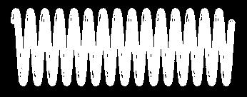
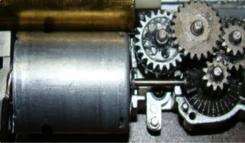

26 * SMA Actuator 액츄에이터 (Actuator) : 전기에너지, 열에너지등의에너지원을운동에너지로전환하여기계장치를움직이도록하는구동소자 기존의매크로스케일액츄에이터 ( 모터 - 기어방식 ) SMA 스프링액츄에이터 SMA Spring Actuator Cooled down (T < Ms) Heated up (T > Af) 재료의수축과신장을통하여기계적인동작을가능하게함. 1. 단위체적당출력이높음 2. 모터구동에비해매우단순한구조 3. 온도에의한제어가용이 4. 소형화가쉬움. 26


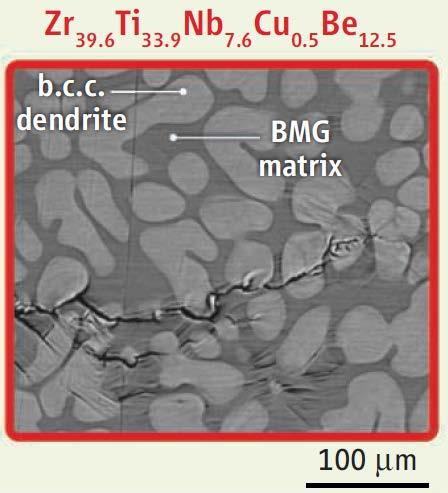
27 Douglas C. Hofmann, SCIENCE VOL SEPTEMBER 2010


28 New Ti-based BMGC Alloy system Cu-Zr-Al system Ti-Cu-Ni system Secondary phase CuZr Metastable B2 phase at RT Shape Memory Behavior Ti-X Stable B2 phase at RT Superelastic behavior Shape Memory Alloy (SMA) Super-Elastic Alloy (SE alloy) Stress α martensite β α Stress α martensite β α α β metastable β α β stable β at RT Mf Ms As Af RT Temperature Mf Ms As Af RT Temperature ESPark Research Group

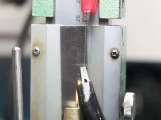
29 B 2 M B 2 - Alloy composition: Ti 49 -Cu-Ni-X Ф3mm suction casting -Fully crystalline B2 Stress-induced phase transformation In-situ neutron diffraction measurement during compression B2 phase Orthorhombic martensite phase Temperature-induced phase transformation DSC measurement (during cooling) 44 Intensity(a.u.) 300um B theta theta(degree) Phase transformation stress = 570MPa Stress(MPa) Intensity Heat Flow (W/g) Orthorhombic martensite (cooling) B2 phase Temperature (celsius degree) Martensite start T (Ms) = -22 Novel Ti-based Super-elastic Crystalline Alloy ESPark Research Group
30 Contents in Phase Transformation Background to understand phase transformation (Ch1) Thermodynamics and Phase Diagrams (Ch2) Diffusion: Kinetics (Ch3) Crystal Interface and Microstructure (Ch4) Solidification: Liquid Solid Representative Phase transformation (Ch5) Diffusional Transformations in Solid: Solid Solid (Ch6) Diffusionless Transformations: Solid Solid 30
31 Microstructure-Properties Relationships Alloy design & Processing Performance Phase Transformation Microstructure down to atomic scale Properties Tailor-made Materials Design 31
32 * Homework 6 : Exercises (pages ) until 14th December (before exam) * IH: Summary of Martensite nucleation & growth Good Luck!! 32
33 FINAL (14th December, 7 PM-10PM) Scopes: Text: page 146 (chapter 3.4) ~ page 397 (chapter 6.2)/ Good Luck!! Teaching notes: 14~25/ QUIZ and Homeworks 33