ENGR 151: Materials of Engineering LECTURE #12-13: DISLOCATIONS AND STRENGTHENING MECHANISMS
|
|
|
- Ronald Potter
- 5 years ago
- Views:
Transcription
1 ENGR 151: Materials of Engineering LECTURE #12-13: DISLOCATIONS AND STRENGTHENING MECHANISMS
2 RECOVERY, RECRYSTALLIZATION, AND GRAIN GROWTH Plastically deforming metal at low temperatures affects physical properties of metal Elevated temperature treatment Recovery Recrystallization
3 RECOVERY Stored internal energy is relieved by dislocation motion as a result of atomic diffusion Physical properties restored (electrical, thermal) Grains are still in a relatively high strain energy state

4 RECRYSTALLIZATION The formation of a new set of strainfree and approximately equal-sized grains after recovery period Low dislocation densities
 and grain boundaries")
5 RECRYSTALLIZATION Difference between dislocation boundaries (cold-worked) and grain boundaries (recrystallized)
6 RECRYSTALLIZATION Small nuclei grow till they completely consume the parent material Recrystallized metal is usually softer, weaker yet more ductile that cold-worked version
7 RECRYSTALLIZATION
8 RECRYSTALLIZATION Recrystallization Temperature Temp at which recrystallization reaches completion in one hour.
9 GRAIN GROWTH After recrystallization, grains continue to grow if elevated temperatures are maintained For grain growth, dependence of grain size on time d 0 = initial grain diameter at t = 0 K = time-independent constant n= time-independent constant

10 GRAIN GROWTH

11 FAILURE (CHAPTER 8)
12 FAILURE (CHAPTER 8) Lockheed cargo plane example
13 FAILURE (CHAPTER 8) Simple fracture is the separation of a body into two or more pieces in response to an imposed static stress (constant or slowly changing with time) and at temperatures relatively low as compared to the material s melting point
14 FRACTURE Stress can be tensile, compressive, shear, or torsional For uniaxial tensile loads: Ductile fracture mode (high plastic deformation) Brittle fracture mode (little or no plastic deformation)
15 FRACTURE Ductile and brittle are relative (ductility is based on percent elongation and percent reduction in area) Fracture process involves two steps: Crack formation & propagation in response to applied stress Ductile fracture characterized by extensive plastic deformation in the vicinity of an advancing crack Process proceeds slowly as crack length is extended.
16 FRACTURE Stable crack: resists further extension unless there is increase in applied stress Brittle fracture: cracks spread extremely rapidly with little accompanying plastic deformation (unstable) Ductile fracture preferred over brittle fracture Brittle fracture occurs suddenly and catastrophically without any warning Ductile fracture gives preemptive warning that fracture is imminent Brittle (ceramics), ductile (metals)

17 DUCTILE FRACTURE Figure 8.1 (differences between highly ductile, moderately ductile, and brittle fracture)
 Cup-and-cone")
18 DUCTILE FRACTURE Common type of fracture occurs after a moderate amount of necking After necking commences, microvoids form Crack forms perpendicular to stress direction Fracture ensues by rapid propagation of crack around the outer perimeter of the neck (45 angle) Cup-and-cone fracture

19 DUCTILE VS. BRITTLE FRACTURE EXAMPLE
20 BRITTLE FRACTURE Takes place without much deformation (rapid crack propagation) Crack motion is nearly perpendicular to direction of tensile stress Fracture surfaces differ: V-shaped chevron markings Lines/ridges that radiate from origin in fan-like pattern Ceramics: relatively shiny and smooth surface

21 BRITTLE FRACTURE
22 BRITTLE FRACTURE Crack propagation corresponds to the successive and repeated breaking of atomic bonds along specific crystallographic planes (cleavage) Transgranular: fracture cracks pass through grains Intergranular: crack propagation is along grain boundaries (only for processed materials)
23 PRINCIPLES OF FRACTURE MECHANICS Quantification of the relationships between material properties, stress level, crackproducing flaws, and propagation mechanisms
24 STRESS CONCENTRATION Fracture strengths for most brittle materials are significantly lower than those predicted by theoretical calculations based on atomic bonding energies. Due to microscopic flaws that exist at surface and within the material (stress raisers)
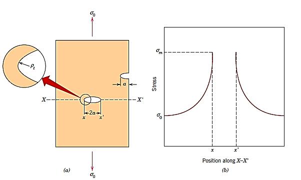
25 STRESS CONCENTRATION

26 MAXIMUM STRESS AT CRACK TIP Assume that a crack is similar to an elliptical hole through a plate, oriented perpendicular to applied stress, then the maximum stress: σ o = applied tensile stress ρ t = radius of curvature of crack tip a = represents the length of a surface crack

27 STRESS CONCENTRATION FACTOR (K T ) Measure of the degree to which an external stress is amplified at the tip of a crack Stress amplification can also take place: Voids, sharp corners, notches Not just at fracture onset
28 BRITTLE MATERIAL Effect of a stress raiser is more significant (stronger) in brittle than ductile materials. In ductile materials, there is a uniform distribution of stress in the vicinity of the stress raiser This phenomenon does not occur in brittle materials

29 BRITTLE MATERIAL Critical stress required for crack propagation in a brittle material: E = modulus of elasticity γ s = specific surface energy a = one half the length of an internal crack When magnitude of tensile stress at tip of flaw exceeds critical stress, fracture results

30 EXAMPLE PROBLEM 8.1 (PG. 244):
31 IMPACT FRACTURE TESTING Charpy V-notch (CVN) technique: Measure impact energy (notch toughness) Specimen is bar-shaped (square cross section) with a V-notch High-velocity pendulum impacts specimen Original height is compared with height reached after impact (energy absorption) Izod Test
32 FATIGUE Form of failure that occurs in structures subjected to dynamic and fluctuating stresses. Failure can occur at stress level considerably lower than tensile of yield strength Occurs after repeated stress/strain cycling Single largest cause of failure in metals

33 CYCLIC STRESSES Axial, flexural, or torsional Three modes Symmetrical Asymmetrical Random Mean stress:


34 CYCLIC STRESSES Range of stress: Stress amplitude: Stress ratio:
35 THE S-N CURVE Fatigue testing apparatus Simultaneous axial, flex, and twisting forces S-N curve (stress vs. number of cycles) Fatigue limit Fatigue strength Fatigue life
36 CREEP Deformation occurring at elevated temperatures and exposed static mechanical
37 HW (DUE MONDAY, APRIL 10) Chapters 7 & , 7.30, 7.38, 8.1, 8.3, 8.22