CELLULOSE NANOWHISKERS AND NANOFIBERS FROM BIOMASS FOR COMPOSITE APPLICATIONS TAO WANG
|
|
|
- Scarlett Burns
- 5 years ago
- Views:
Transcription
1 CELLULOSE NANOWHISKERS AND NANOFIBERS FROM BIOMASS FOR COMPOSITE APPLICATIONS By TAO WANG A DISSERTATION Submitted to Michigan State University in partial fulfillment of the requirements for the degree of DOCTOR OF PHILOSOPHY CHEMICAL ENGINEERING 2011
2 ABSTRACT CELLULOSE NANOWHISKERS AND NANOFIBERS FROM BIOMASS FOR COMPOSITE APPLICATIONS By TAO WANG Biological nanocomposites such as plant cell wall exhibit high mechanical properties at a light weight. The secret of the rigidity and strength of the cell wall lies in its main structural component cellulose. Native cellulose exists as highly-ordered microfibrils, which are just a few nanometers wide and have been found to be stiffer than many synthetic fibers. In the quest for sustainable development around the world, using cellulose microfibrils from plant materials as renewable alternatives to conventional reinforcement materials such as glass fibers and carbon fibers is generating particular interest. In this research, by mechanical disintegration and by controlled chemical hydrolysis, both cellulose nanofibers and nanowhiskers were extracted from the cell wall of an agricultural waste, wheat straw. The reinforcement performances of the two nanofillers were then studied and compared using the watersoluble polyvinyl alcohol (PVOH) as a matrix material. It was found that while both of these nanofillers could impart higher stiffness to the polymer, the nanofibers from biomass were more effective in composite reinforcement than the cellulose crystals thanks to their large aspect ratio and their ability to form interconnected network structures through hydrogen bonding. One of the biggest challenges in the development of cellulose nanocomposites is achieving good dispersion. Because of the high density of hydroxyl groups on the surface of cellulose, it remains a difficult task to disperse cellulose nanofibers in many
3 commonly used polymer matrices. The present work addresses this issue by developing a water-based route taking advantage of polymer colloidal suspensions. Combining cellulose nanofibers with one of the most important biopolymers, poly(lactic acid) (PLA), we have prepared nanocomposites with excellent fiber dispersion and improved modulus and strength. The bio-based nanocomposites have a great potential to serve as light-weight structural materials for automotive, medical, and other applications.
4 ACKNOWLEDGMENTS It is with great pleasure that I thank my research advisor, Prof. Lawrence T. Drzal, for his guidance, support, encouragement, and patience during my graduate studies. I also thank Prof. Bruce Dale for his guidance as an advisor at the early stage of this project and his continued support as a committee member. I thank Profs. Chris Saffron and Ilsoon Lee for their advice and words of encouragement. I would also like to thank Profs. Amar Mohanty and Manju Misra (now with University of Guelph, Ontario, Canada) for helping me to start this research. Many thanks go to my friends and colleagues in the Composite Materials and Structures Center (CMSC) and the Department of Chemical Engineering and Materials Science. Special thanks to Drs. Wanjun Liu, Jue Lu (now with Technova Corporation), and Hiroyuki Fukushima. I am deeply indebted to Dr. Farzaneh Teymouri at MBI International (Lansing, MI) for her kind support and friendship in the past few years. It has been a wonderful experience collaborating with her, Janette Moore, and other researchers at MBI. I thank all the staff members at the CMSC, Dr. Per Askeland, Ed Drown, Robert Jurek (now with Performance Polymer Solutions Inc.), Kelby Thayer (now with School of Packaging), and Mike Rich for training and helping with operating all the instruments. Special thanks to Brian Rook for his help with the high-pressure homogenizer. I thank Mr. Toshiya Kamae (Toray Industries, Inc., Japan) for providing me with great ideas and assistance during his visit in MSU. iv
5 I feel very grateful to Dr. Alicia Pastor, Ewa Danielewicz (now with Lansing Community College), Dr. Shirley Owens (retired), Carol Flegler, Dr. Xudong Fan, Dr. Melinda Frame, and Dr. Stanley Flegler in the Center for Advanced Microscopy for their help with electron and confocal microscopy. I learned a lot from discussions with Prof. Venkatesh Balan and other members of Prof. Dale s group. I thank Dr. Hasan Alizadeh (retired) for providing assistance with Ammonia Fiber Expansion (AFEX) at the beginning of this project. I would also like to thank Prof. John Partridge and Rodney Clark in the Department of Food Science and Human Nutrition and MSU Dairy Plant for making the APV homogenizer available for this work. I thank Prof. David Martin at University of Michigan and his former student, Dr. Jihua Chen, for their help with low-dose transmission electron microscopy and electron diffraction. v
6 TABLE OF CONTENTS LIST OF TABLES...IX LIST OF FIGURES...X ABBREVIATIONS...XIII CHAPTER 1 INTRODUCTION AND BACKGROUND Plant cell wall a biological nanocomposite Application of cellulose in nanocomposites Microcrystalline Cellulose (MCC) and composites Cellulose nanofibers Microfibrillated Cellulose (MFC) Cellulose nanocrystals Cellulose Nanowhiskers (CNWs) Challenges of cellulose nanocomposite fabrications Solution film casting Surface modifications Using wheat straw as feedstock The advantages of wheat straw Feasibility and challenges of using wheat straw References CHAPTER 2 EXTRACTION OF CELLULOSE NANOFIBERS AND NANOWHISKERS FROM WHEAT STRAW Introduction Experimental details Results and discussion MFC extracted from wheat straw CNWs extracted from wheat straw References CHAPTER 3 MFC AND CNW REINFORCED PVOH NANOCOMPOSITES Introduction Motivation Objectives Experimental details Results Evaluation of dispersion vi
7 3.3.2 Mechanical and thermal properties Model calculations Discussion and conclusions References CHAPTER 4 MFC REINFORCED POLYLACTIC ACID NANOCOMPOSITES Motivation Background Introduction to PLA The need for PLA composites Challenges in PLA nanocomposite fabrications Summary of the water-based processing route Colloidal suspension of PLA microspheres Water removal after mixing Experimental details Results Nanofibers obtained from wood and wheat straw PDLLA microspheres Evaluation of dispersion and adhesion Mechanical properties of the PDLLA composites Effectiveness of MFC extracted from wheat straw Comparison of thermal stabilities Discussion and conclusions References CHAPTER 5 CONCLUSIONS AND RECOMMENDED FUTURE STUDIES Conclusions Cellulose nanoreinforcements from wheat straw Cellulose-based PLA nanocomposites Recommended future studies PLA stabilizers Impact properties and fracture toughness of the PLA nanocomposites Effect on the crystallization behavior of PLA Wheat straw biorefinery References APPENDIX A DELIGNIFICATION METHODS APPENDIX B CNWS PRODUCED FROM MICROCRYSTALLINE CELLULOSE APPENDIX C MFC AND CNW PRODUCTION COST ESTIMATES vii
8 APPENDIX D FINDING A SUITABLE SURFACTANT APPENDIX E REMOVAL OF WATER FROM THE CELLULOSE PLA MIXTURE APPENDIX F WHEAT STRAW ETHANOL PRODUCTION RESIDUE viii
9 LIST OF TABLES Table 1-1 Density and mechanical properties of crystalline cellulose compared to commonly used fibers... 4 Table 4-1 Flexural properties of PLLA compared with those of commonly used implant materials and human cortical bone Table 4-2 Testing results of the flexural properties of the 32 wt% wheat straw MFC reinforced PDLLA composite Table C-1 Process economics of MFC production Table C-2 Process economics of CNW production Table F-1 Carbohydrate compositions of the raw wheat straw and the fermentation residue (%) Table F-2 The O/C atomic ratio and the relative C1, C2, and C3 peak areas of the deconvoluted C1s peak obtained by XPS analysis ix
10 LIST OF FIGURES Figure 2-1 TEM micrographs of the wheat straw MFC. (a) Low-magnification image showing fiber width distribution; (b) High-resolution image showing the size of individual microfibrils Figure 2-2 Wheat straw cellulose hydrolyzed for (a) 30 min; (b) 2 h; and (c) 4 h Figure 2-3 TEM micrographs of the extracted wheat straw CNWs negatively stained with uranyl acetate Figure 3-1 The transparent wheat straw CNW / PVOH composite films. CNW weight content from left to right: 0%, 1%, 3%, 5%, and 10%. (For interpretation of the references to color in this and all other figures, the reader is referred to the electronic version of this dissertation.) Figure 3-2 Wheat straw MFC / PVOH composite films. MFC weight content from left to right: 0%, 1%, 3%, 5%, and 10% Figure 3-3 Fracture surfaces of the wheat straw CNW / PVOH composite films. (a) 1 wt%; (b) 3wt%; (c) 5wt%; and (d) 10wt% Figure 3-4 Fracture surfaces of the wheat straw MFC / PVOH composite films. (a) 1wt%; (b) 3 wt%; (c) 5wt%; and (d) 10wt% Figure 3-5 The surface of the 10 wt% wheat straw MFC reinforced PVOH composite film (a) before and (b,c) after plasma etching Figure 3-6 Plasma etched surfaces of (a) neat PVOH and (b) 1 wt%, (c) 3 wt%, (d) 5 wt%, and (e) 10 wt% CNW/PVOH films Figure 3-7 High-magnification images of the plasma etched (a) PVOH and (b) 1 wt%, (c) 3 wt%, (d) 5 wt%, and (e) 10 wt% CNW / PVOH films Figure 3-8 DMA of the CNW reinforced PVOH films: (a) Storage moduli (b) Tan δ Figure 3-9 DMA of the MFC reinforced PVOH films: (a) Storage moduli (b) Tan δ Figure 3-10 TGA curves of the (a) CNW- and (b) MFC- based composites Figure 3-11 Tensile storage moduli of the wheat straw CNW reinforced PVOH composites at 0 C: A comparison between the experimental data and the calculated values x
11 Figure 4-1 The chemical structure of Polysorbate Figure 4-2 A comparison of the (a) wood MFC and (b) MFC extracted from wheat straw Figure 4-3 TEM micrographs of wheat straw MFC negatively stained with 1 wt% uranyl acetate. Image in (b) is a close-up image showing individual microfibrils Figure 4-4 PDLLA microspheres produced by using the emulsion solvent evaporation technique Figure 4-5 Fracture surfaces of the composites reinforced with (a) 8wt%, (b) 15wt%, and (c) 32 wt% wood MFC, and (d) 32wt% wheat straw MFC Figure 4-6 Comparison of the (a) flexural modulus and (b) strength of the neat PDLLA and the wood MFC reinforced composites Figure 4-7 Comparison of the storage moduli of the neat PDLLA and the wood MFC reinforced composites Figure 4-8 SEM images showing the defect at the fracture surface of the 2nd test specimen in table 2. (a) An overview and (b) a close-up image of the defect Figure 4-9 A comparison of the (a) flexural modulus and (b) strength of the PDLLA reinforced with wheat straw MFC and wood MFC Figure 4-10 A comparison of the storage moduli of the 32wt% wheat straw MFC / PDLLA and wood MFC / PDLLA Figure 4-11 Comparison of the thermal stabilities of the PDLLA and the MFC/PDLLA composites Figure B-1 ESEM image of the as-received microcrystalline cellulose (MCC) Figure B-2 TEM micrograph of the CNWs obtained from MCC by acid hydrolysis Figure B-3 AFM tapping mode height image of the CNWs Figure C-1 The cost of producing the MFC at different production capacities Figure C-2 Sensitivity analysis of the MFC production Figure C-3 The cost of producing the CNW at different production capacities Figure D-1 Samples obtained by solvent evaporation using SDS as surfactant (a) without ultrasonication; (b) with ultrasonication xi
12 Figure D-2 PDLLA microspheres produced by using Carbopol 940 as surfactant Figure D-3 Chemical structure of Triton X Figure D-4 PDLLA microspheres produced by using Triton X-100 as surfactant Figure D-5 PDLLA microspheres prepared by using Polysorbate 80 as surfactant. The surfactant-to-polymer ratio is: (a) 8:100 and (b) 3:100. Lower surfactant content results in greater particle size and size distribution Figure E-1 A comparison of the (a) flexural modulus and (b) strength of the neat PDLLA and 5 wt% wood MFC / PDLLA composite prepared by freeze drying Figure E-2 The fracture surface of the 5wt% wheat straw MFC / PDLLA composite prepared by membrane filtration. (a) Distinguished cellulose-rich layers embedded in the polymer matrix; (b) A close-up image showing the cellulose-rich region Figure E-3 The MFC / PDLLA composites prepared with surfactant-to-polymer ratios of (a) 8:100 and (b) 3: Figure E-4 The fracture surface of the 5wt% wood MFC/PDLLA composite prepared by centrifugation and SpeedMixer mixing. (a) An overview of the surface; (b) MFC aggregates Figure E-5 The fracture surface of the wood MFC / PDLLA composite prepared by repeated mixing of the PDLLA microspheres into a MFC hydrogel. (a) MFC is distributed as small islands inside the polymer matrix; (b) The fibers are highly concentrated inside each aggregate Figure F-1 SEM micrographs showing the surfaces of (a) raw wheat straw and (b) the fermentation residue Figure F-2 The fusing together morphology on the surface of the residue Figure F-3 FTIR spectra of raw wheat straw and the fermentation residue Figure F-4 TEM micrograph of the MFC extracted from the wheat straw fermentation residue xii
13 ABBREVIATIONS AFM CNW DI DMA DP ESEM FE-SEM FTIR LODP MCC MFC MWCO PDLA PDLLA PEG PGA PLA PLGA PLLA PVOH RO Atomic force microscopy or microscope Cellulose Nanowhisker deionized Dynamic mechanical analysis or analyzer degree of polymerization Environmental scanning electron microscopy or microscope Field emission scanning electron microscopy or microscope Fourier transform infrared spectroscopy Leveling-off degree of polymerization Microcrystalline Cellulose Microfibrillated Cellulose molecular weight cut-off poly(d-lactic acid) poly(dl-lactic acid) polyethylene glycol poly(glycolic acid) poly(lactic acid) poly(lactic-co-glycolic acid) poly(l-lactic acid) polyvinyl alcohol reverse osmosis xiii
14 SEM TEM T g TGA WS XPS Scanning electron microscopy or microscope Transmission electron microscopy or microscope glass transition temperature Thermogravimetric analysis or analyzer wheat straw X-ray photoelectron spectroscopy xiv
15 CHAPTER 1 INTRODUCTION AND BACKGROUND The global mission of achieving sustainable growth for humankind within this century has demanded the development of new materials that meet our needs and at the same time are environmentally friendly and renewable. This has led to an immense amount of research interest being devoted to biobased polymers and composites in the last two decades. 1,2 At around the same time, we are also witnessing a fast advancement in the development of polymer nanocomposites, which are polymers reinforced with spheres, fibers, or plates that have at least one dimension below 100 nm. 3 The nanoscopic nature of the filler and hence the large relative surface area contribute to the unique mechanical, thermal, electrical, and optical properties of the composites, providing an array of opportunities in the design and manufacture of lightweight structural materials as well as advanced biomedical and electronic devices. 4,5 By using biobased nanoreinforcements, we create biomimicking materials that have the potential to combine the advantages of both nanocomposites and biocomposites. The present work is directed at evaluating the potential of using agricultural wastes as raw materials for extracting cellulose nanofillers and finding a method to solve the difficult problem of achieving good dispersions in cellulose nanocomposites. 1
16 1.1 Plant cell wall a biological nanocomposite Nature creates hierarchical structures to realize different functions. Among these hierarchical structures, biological nanocomposites such as bones, seashells, and cell walls can serve as important inspirations for material design. 6 Plant cells rely on the cell wall located outside the cell membrane to provide protection and maintain structural integrity. The cell wall gives cells rigidity and strength as well as flexibility, which are often the desired properties in material design. Progress made in the last few decades on the understanding of these smart biological systems has revealed that the good mechanical properties of the cell wall can be attributed mainly to two reasons: the stiffness of the crystalline cellulose and the hierarchical structure. In the cell wall, cellulose microfibrils are linked with hemicellulose to form a cellulose-hemicellulose network, which is embedded in the lignin matrix. Cellulose microfibrils are the structural component of all higher plants and many forms of algae. Tunicates are the only animals able to create cellulose by biosynthesis. 7 The microfibrils are formed by just a few dozen parallel, hydrogen-bonded cellulose molecules. The width of the microfibrils is smaller for vascular plant such as trees (3 to 4 nm), 8 and larger for algae such as Valonia (20 nm), 9 and animals such as tunicates (10 nm). 10 Cellulose microfibrils have both crystalline regions and disordered amorphous regions. 11 While there are several different crystalline structures of cellulose, native cellulose is cellulose I, consisting of two different allomorphs, I α and I β. Bacterial and algal cellulose is rich in I α, while cellulose of higher plants consists mainly of I β. 12 2
17 Crystalline cellulose is a very stiff material. The elastic modulus of cellulose I s crystalline region in the direction parallel to the chain axis has been measured by x-ray diffraction to be GPa and 138 GPa in two separate studies. 13,14 Based on molecular simulation techniques, theoretical values between 124 to 155 GPa have also been reported. 15 Recently, the elastic modulus of single tunicate microfibrils prepared by acid hydrolysis was determined to be GPa by a three-point bending test using an atomic force microscope (AFM). 16 A comparison of the density and mechanical properties of crystalline cellulose and commonly used composite reinforcing fibers is shown in Table 1-1. The high elastic modulus and low density of the crystalline cellulose in the microfibrils give them the potential to become alternatives to conventional reinforcement materials such as glass fibers and carbon fibers. By extracting cellulose from plant materials and using it as a reinforcing element in polymer composites, we can create biomimicking structures that are useful and sustainable. 1.2 Application of cellulose in nanocomposites Although a cellulose product with high crystallinity, Microcrystalline Cellulose (MCC) has been isolated from native cellulose for more than half of a century, the initiative of using cellulose in composite applications was not started until about 15 years ago. Cellulose has been used in materials research mainly in two forms: the nanocrystals and nanofibers. The nanocrystals are commonly called Cellulose Nanowhiskers (CNWs) and the nanofibers are conventionally referred to as Microfibrillated Cellulose (MFC). In this section, an overview of the progress that has 3
18 been made in the development of MCC, CNW, and MFC based composites is given and the challenges that still remain are then discussed. Table 1-1 Density and mechanical properties of crystalline cellulose compared to commonly used fibers Density Young s modulus Tensile strength Fiber (g cm -3 ) (GPa) (MPa) Crystalline cellulose 14, Jute fiber Flax fiber ,100 E-glass fiber ~72.4 at 21 C ~3,400 at 21 C Carbon fiber , Microcrystalline Cellulose (MCC) and composites MCC is partially depolymerized cellulose prepared from α-cellulose by acid hydrolysis. The α-cellulose obtained from plant fibers such as wood pulp and cotton is treated with mineral acids, which dissolve the amorphous region of the cellulose chains while leaving the crystalline part intact. The hydrolysis is usually carried out until the leveling-off degree of polymerization (LODP) is reached. MCC is an odourless and tasteless white powder. It does not dissolve in water, dilute acid, and most organic solvents. 4
19 The pioneering work of Battista and coworkers in the 1950s on MCC studies led to the commercialization of AVICEL by FMC Cooperation in the 1960s. 21,22 Today, MCC is commercially available with varying particle sizes, typically from 20 to 200 μm. It is widely used in the pharmaceutical industry as an inactive binder in drug tablets. 23 MCC is an excellent carrier for non-crystalline drugs and provides strength to the tablet. Other applications of MCC include fat-free food additives and suspension stabilizers in the food and cosmetic industries. On the industrial scale, MCC is mainly obtained from dissolving-grade wood pulp. In an effort to reduce production cost, there have been studies on preparing MCC from biomass such as wheat straw, 24 rice straw, 25 and bagasse. 26 The properties of MCC obtained from these sources were reported to be comparable to those of the commercially available products. Although having high crystallinity, MCC has not attracted much interest in the composite area due to its particulate nature. But since MCC powder can be considered as aggregates of cellulose nanocrystals, recently the possibility of using MCC as a filler in composites has been explored. Using Raman spectroscopy, Eichhorn and Young estimated the Young s modulus of MCC to be 25 ± 4 GPa. 27 Borges et al. studied the tensile properties of Avicel MCC-reinforced 2-hydroxypropylcellulose (HPC) composite films. 28 The MCC used was in short fiber form, with an average length of 30 μm and an aspect ratio of about 5. Diisocyanate was used as a coupling agent. It was found that the Young s moduli of the films increased with MCC content up to 20 wt%, both with and without coupling agent, from about 125 MPa to 390 MPa and 314 MPa respectively. Modulus 5
20 improvement was also observed in polyurethane and polypropylene composites by using Avicel MCC. 29,30 MCC-reinforced poly(lactic acid) (PLA) composite was prepared using a twinscrew extruder by Mathew et al. 31 The MCC used was a powder with particle size of μm. The addition of 25 wt% MCC increased the elastic modulus of PLA from 3.6 GPa to 5.0 GPa, and decreased the tensile strength from 49.6MPa to 36.2 MPa. While wood flour and wood fiber composites were prepared by the same method for comparison purposes, both of them showed properties superior to the MCC composites. The poor adhesion between the MCC and the PLA matrix was responsible for the inefficient stress transfer, and the low aspect ratio (about 1) contributed to the low elongation at break. In addition, although the MCC powder added was expected to be disintegrated into cellulose nanofibers or nanocrystals by the shearing force generated in the extrusion process, it was found that the particles retained their original morphology in the composites. An interesting development of MCC composites in recent years is the selfreinforcement of this material. By partially dissolving MCC in a lithium chloride / N,Ndimethylacetamide (LiCl/DMAc) solution, Gindl and Keckes obtained all-cellulose nanocomposite films. 32 In this type of composites, the undissolved MCC retained the crystalline structure of Cellulose I and acted as reinforcement, while the dissolved MCC recrystallized into regenerated cellulose (Cellulose II), playing the role of the matrix. Compared with pure regenerated cellulose films produced by dissolving Lyocell fibers, the all-cellulose composites with 24 to 59% of cellulose I showed significant improvement in elastic moduli and strength. The excellent optical transparency was 6
21 given as evidence to support the nanocomposite nature of the Cellulose I/Cellulose II blend. Using a similar system, Abbott and Bismarck found that increased dissolution time led to a reduction of the degree of crystallinity of the regenerated cellulose, which then resulted in a decrease in the mechanical performance and thermal stability of the composite films Cellulose nanofibers Microfibrillated Cellulose (MFC) Cellulose nanofibers produced from native cellulose using different microfibrillation methods were named Microfibrillated Cellulose (MFC) when they were first prepared and characterized by Herrick et al. and Turbak et al. in ,35 By repeated homogenization at a pressure of 55 MPa, wood pulp fibers were disintegrated into fibers with widths of nm. Hence MFC is mechanically individualized native cellulose microfibrils. Very importantly the chain length or the degree of polymerization (DP) of the original cellulose microfibrils is only slightly reduced in this mechanical process, resulting in very high length-to-width aspect ratio. MFC is now commercially available and is usually still obtained by applying highpressure homogenization on wood pulp. Daicel Chemical Industries, Ltd. in Japan is the only company known to the author to provide MFC with a diameter less than 100 nm. Besides the commonly used homogenizing process, a super-grinding process was developed by Taniguchi and Okamura in the late 1990s to prepare very fine MFC. 36 Microfibrils with diameters ranging from 20 to 90 nm were obtained from wood pulp, cotton cellulose, tunicin cellulose, chitosan, silk fibers, and collagen. MFC has been 7
22 used mainly as filter media, additives in low-calorie food, and additives in papermaking to improve paper strength. 37 Early investigations of using MFC as a reinforcement material in polymer composites were often based on cellulose sources rich in parenchyma cells, and the results were not very encouraging. Dufresne et al. studied the mechanical properties of films prepared from sugar beet MFC in the late 1990s. 38 The tensile modulus was measured to be 2-3 GPa and decreased with increased moisture content. A polymer latex reinforced with 6 wt% sugar beet MFC showed improvement in its tensile storage modulus only in the polymer s rubbery state above the T g. 39 However, since the mid- 2000s, there has been a renewed interest in using high-quality MFC to produce highstrength nanocomposites for applications in biomedical and electronic devices. In their development of bamboo fiber reinforced PLA composites, Fujii et al. found that adding a small amount of MFC enhanced the composites bending strength and fracture toughness. 40 MFC sheets impregnated with up to 7.4 wt% phenol-formaldehyde (PF) resin prepared by Nakagaito and Yano showed Young s modulus as high as GPa. 41 Furthermore, it has been demonstrated that by impregnating MFC paper with acrylic resins, flexible and optically transparent films can be made, which have a potential to be used as electronic displays Cellulose nanocrystals Cellulose Nanowhiskers (CNWs) As mentioned earlier, cellulose microfibrils contain both crystalline and disordered amorphous domains. By disintegrating the microfibril bundles and controlled 8
23 hydrolysis of the amorphous domains, individual cellulose microcrystallites can be released into water, forming a colloidal suspension. Unlike MCC particles, these cellulose microcrystallites are tiny rods or filaments with a defined morphology. Because of their needle-like structure and high crystallinity and stiffness, cellulose microcrystallites draw comparisons to metal and ceramic whiskers such as tin (Sn) whiskers and silicon carbide (SiC) whiskers, hence are also called Cellulose Nanowhiskers (CNWs). In 1952, Ranby published his work on isolating cellulose micelles from cotton and wood cellulose by sulfuric acid hydrolysis and ultrasonic wave treatment. These cellulose micelles were highly crystalline and had a dimension of about 60 Angstrom wide and more than 600 Angstrom long. 43 While this was the first comprehensive study on the preparation and characterization of cellulose microcrystallites, the method of obtaining them has remained largely unchanged until today. Because of their unique optical, rheological and mechanical properties, cellulose microcrystallites have remained an interesting research subject for decades. Revol et al. prepared cellulose microcrystallites from wood pulp and studied the birefringent character of their suspensions. 44 It was found that above a critical concentration, the colloidal dispersion of the cellulose microcrystallites forms spontaneously into a chiral nematic liquid crystal phase. Dong et al. then studied the relationship between the formation of the ordered phase and the microcrystallite concentration as well as the effect of added electrolytes. 45 Although cellulose microcrystallites were known to be a strong material, not until about 15 years ago did researchers start investigating the application of these crystals 9
24 as a strengthening material in nanocomposites. 46 In 1995, Favier et al. published their study on extracting CNWs from tunicates and adding them to a polymer latex made from styrene, butyl acrylate, and acrylic acid. 47 They found that the expected decrease of the storage shear modulus above the T g of the composite films was greatly reduced in magnitude with the addition of the CNWs. The strong performance obtained by adding just a small percentage of CNWs was explained by a percolation phenomenon. This paper demonstrated, for the first time, the reinforcing potential of CNWs. Since then, CNWs have been extracted from different raw materials and CNW-based nanocomposites have been attracting growing research interest. 48 The matrix materials used in the early studies of CNW nanocomposites were mainly polymer latices 49, 50 and water-soluble polymers such as poly(oxyethylene) (POE), and polyvinyl alcohol (PVOH). 51,52 Because of the hydrophilic nature of CNWs, using water-soluble polymers makes composite processing straightforward, and good dispersion and adhesion can often be achieved. 1.3 Challenges of cellulose nanocomposite fabrications The successful biomimicking of the plant cell wall is to have the mechanical properties of the nanoscale microfibrils fully realized in the bulk materials. Despite having many attractive properties, cellulose-based nanocomposites have not found wide-spread applications on the industrial scale mainly due to the high cost of extraction, difficulties in material processing, and some disadvantages associated with cellulose fillers. Some of the disadvantages of cellulose include moisture absorption, 10
25 and inconsistency in properties resulting from varying source materials. Furthermore, the upper limit of the processing temperature of composites is only about 200 C since cellulose starts to degrade at about C. However, because of the inherent hydrophilic nature of polysaccharides, the biggest technical challenges in the development of cellulose-based nanocomposites have been the difficulties of achieving a uniform distribution in nonpolar matrices and a good adhesion to ensure effective load transfer from the reinforcement to the matrix. Different methods have been proposed to solve the dispersion problem. Solution film casting using organic solvents is one of the most popular. Surface modifications have also been proposed to enhance the stability of these fillers in organic solvents and their affinity with nonpolar polymer materials Solution film casting In this method, cellulose nanofillers are dispersed in an organic solvent and mixed with polymers that have been previously dissolved in the same solvent. Controlled solvent evaporation results in composite films, which can then be studied directly or further processed. The solvents used can be either water-miscible or waterimmiscible. Thanks to the polar nature of cellulose, more success has been found in solvents with higher polarity such as ethanol, acetone, dimethyl sulfoxide (DMSO), tetrahydrofuran (THF), and N, N-dimethylformamide (DMF) than in those with lower polarity such as toluene and hexane. MFC and CNWs are usually transferred from water into this solvent either by solvent exchange or by drying and re-dispersing. It has been shown in several studies that freeze-dried CNWs can form stable suspensions in 11
26 DMF, and by using DMF as a solvent CNW-based poly(oxyethylene) composite, 53 poly(3-hydroxybutyrate-co-3-hydroxyvalerate) (PHBV) composite, 54,55 poly(vinyl acetate) (PVAc), and poly(butyl methacrylate) (PBMA) composites were prepared by film casting. 56 In another study, without the drying step, CNWs were dispersed in acetone through solvent exchange, mixed with cellulose acetate butyrate (CAB) acetone solution, and then cast into films by Ayuk et al. 57 Recently, CNW reinforced polylactic acid (PLA) composites have been prepared by using chloroform as the dispersion medium. 58,59 On the other hand, when a water-miscible solvent is used, the MFC or CNW water suspension and the polymer solution can also be mixed directly. By mixing tunicate CNW water suspensions with an ethylene oxide epichlorohydrin (EO- EPI) copolymer dissolved in THF and by solution casting and compression molding, Schroers et al. obtained homogeneous nanocomposite films, which showed a large improvement in Young s modulus. 60 Solution casting method is usually limited to producing thin films. Although good dispersion can be achieved, the fillers cannot be incorporated into polymers by simple melt compounding as desired in the industries and the high cost involved in freeze drying and solvent exchange processes makes them economically unfavorable Surface modifications Surface modifications of MFC and CNWs have been carried out to block or convert the surface hydroxyl groups in order to prevent the formation of strong interfibril hydrogen bonds. Such modifications can be achieved by (1) coating with surfactants, 12
27 (2) surface oxidation, and (3) surface grafting. By using a surfactant called Beycostat NA (a phosphoric ester of polyoxyethylene nonylphenyl ether), Heux et al. obtained stable dispersions of CNWs in nonpolar solvents, namely toluene and cyclohexane. 61 However, since coating the high-specific-surface-area CNWs requires a large amount of surfactant (the ratio of surfactant to cellulose in the above reference was 4:1 by weight), the use of this technique in composite processing is rather difficult. Surface modification by oxidation has to prevent the oxidation reaction from reaching beyond the surface hydroxyl groups. In the mid-1990s, de Nooy et al. found that by using an organic nitroxyl radical (2,2,6,6-tetramethyl-1-piperidinyloxy or TEMPO) as a mediator, the primary alcohol groups of water-soluble polysaccharides can be selectively oxidized by sodium hypochlorite. 62 This TEMPO-mediated oxidation was found to introduce carboxylate and aldehyde functional groups only on the surfaces of cellulose microfibrils and cause no change to the crystallinity and the crystalline and microfibrillar structures of native cellulose. 63,64, 65 The cellulose nanofillers thus modified became readily re-dispersible in water. 66 Surface grafting of MFC and CNWs mainly includes surface acetylation and surface silylation. The acetylation of tunicate and Valonia CNWs was first studied by Sassi and Chanzy. 67 It was found that the acetylation reaction happened only on the surfaces of the crystalline cellulose, reducing the diameter and, to a less extent, the length of the crystals. Partial silylation has been found to maintain the morphological integrity of CNWs and stabilize them in organic solvents of medium polarity such as acetone and THF, while harsher silylation conditions may cause destruction of the 13
28 crystals. 68 Other functional groups that have been grafted onto the surfaces of both MFC and CNWs include poly(ethylene glycol) (PEG), 69 glycidyl methacrylate, hexamethylene diisocyanate, 70 and various carboxylic acids and their derivatives. 71,72 The large improvement in polymer mechanical properties by adding a small percentage of MFC and CNWs has been attributed not only to the high stiffness and strength of crystalline cellulose but also to the percolation effect of these fibers forming a network structure. Although surface modification may make it easier to disperse these cellulose nanofillers in polymer matrices, their ability to form the network may have been sacrificed at the same time, thus leading to unexpected poor performance of the final products. A comparison of native and trimethylsilylated bacterial CNWs by Grunert and Winter showed better reinforcement characteristics for the native CNWs. 73 Similarly, Habibi and Dufresne reported that, compared with ramie CNWs grafted with polycaprolactone (PCL) chains, the unmodified CNWs improved the tensile modulus of PCL to a higher degree Using wheat straw as feedstock Cellulose is found in the cell wall of all green plants. As the result of an initiative to generate value-added byproducts from agricultural wastes, in the present work wheat straw is being evaluated a feedstock for extracting cellulose nanoreinforcements. 14
29 1.4.1 The advantages of wheat straw Wheat is one of the major crops grown in the world. According to the United Nations statistics, in 2008, the United States alone produced 68.0 million metric tons of wheat and the worldwide production was million tons. 75 About lbs of straw are produced per lb of wheat grain. 76 Wheat straw is an abundant biomass that is currently under-exploited. After the wheat grain is harvested, part of the crop residue has to remain in the field to preserve soil fertility. However, farmers around the world also face the yearly challenge of removing the excess residue from their fields without inducing extra expenses and creating ecological problems. Currently, excess crop residues are usually burned or plowed back into the soil. The removal of straw by field burning, for example, is a questionable practice, since it is often detrimental to the soil, hazardous to the environment, and can cause health problems. Wheat straw has no current widespread use in the US. Thus it is worth exploring the opportunities of using wheat straw as an inexpensive, abundant, and sustainable source for cellulose nanoreinforcements Feasibility and challenges of using wheat straw Wheat straw contains 35-45% cellulose, 20-30% hemicellulose, and 8-15% lignin. 76 It has been attracting world-wide interest recently mainly because it is one of the major biomass types used for biofuel production. Use of wheat straw cellulose fibers for paper-making has been practiced for centuries. Indeed, paper was made from straw materials long before wood pulping became wide-spread. In addition, among common 15
30 crop fibers, wheat straw fibers have been known even to our ancestors to be one of the strongest among the crop stalks, and thus have been used since ancient times for thatching and for making shoes. On the other hand, since the stem of wheat is rich in parenchyma cells and lacks the thick-walled sclerenchyma cells, wheat straw has lower crystalline cellulose content than wood and fiber crops. In the macroscopic scale, the stiffness of wheat straw fibers is not very high. Some reported numbers of the elastic modulus of wheat straw fibers are 2.8 GPa, 77 and 3.6 GPa. 78 However, the situation can be different at the microscopic level. A recent study of the stiffness of crop stalk cell walls by nanoindentation showed that the elastic modulus of the crop cell walls was comparable to that of hardwood cell walls. 79 The cell wall of wheat straw was found to have the highest elastic modulus of 20.8 GPa among the crop stalks tested. Although there is no data yet available on the modulus of individual microfibrils in wheat straw, it is reasonable to assume that they should have similar properties as microfibrils from trees and other plant materials. Very few studies have been done on using microfibrils and nanocrystals from wheat straw for composite applications. The first one was published in 1996 by Helbert et al. 80 CNWs were extracted from wheat straw and were used to reinforce a latex made from styrene, butyl acrylate, acrylic acid, and acrylamide. The fracture surfaces of the composites showed that the CNWs were not well dispersed in the matrix. Although adding CNWs was found to have a reinforcing effect for this rubber material at high temperatures, the storage modulus of the composite with 25 wt% CNWs was only about 16
31 15 MPa at 50 degrees above the T g. Wheat straw MFC was also found to improve the tensile modulus and strength of plasticized thermoplastic starch (TPS). 81 These early studies of cellulose nanofillers were mostly restricted to making thin films and the polymers used often had very low elastic modulus, well below that of the typical thermoplastics. In this work, the properties of both cellulose nanowhiskers (CNWs) and nanofibers (the MFC) extracted from wheat straw are evaluated. Major effort is devoted to incorporating the cellulose nanofillers into non-water-soluble biopolymers with a goal to create nanocomposites that can be used for structural material applications. 17
32 References 18
33 References 1 George, G., Joseph, K., Boudenne, A., and Thomas, S., Recent advances in green composites, Key Engineering Materials, 2010, 425, Pandey, J. K., Ahn, S. H., Lee, C. S., Mohanty, A. K., and Misra, M., Recent advances in the application of natural fiber based composites, Macromolecular Materials and Engineering, 2010, 295(11), Winey, K. I., and Vaia, R. A., Polymer Nanocomposites, MRS Bulletin, 2007, 32(4), Hussain, F., Hojjati, M., Okamoto, M., and Gorga, R. E., Polymer-matrix nanocomposites, processing, manufacturing, and application: An overview, Journal of Composite Materials, 2006, 40(17), Tjong, S. C., Structural and mechanical properties of polymer nanocomposites, Materials Science and Engineering R: Reports, 2006, 53(3-4), Ji, B., and Gao, H, Mechanical principles of biological nanocomposites, Annual Review of Materials Research, 2010, 40, Sasakura, Y., Nakashima, K., Awazu, S., Matsuoka, T., Nakayama, A., Azuma, J., and Satoh, N., Transposon-mediated insertional mutagenesis revealed the functions of animal cellulose synthase in the ascidian Ciona intestinalis, Proceedings of the National Academy of Sciences of the United States of America, 2005, 102(42), Hult, E.-L., Iversen, T., and Sugiyama, J., Characterization of the supermolecular structure of cellulose in wood pulp fibres, Cellulose, 2003, 10(2), Kim, N.-H., Imai, T., Wada, M., and Sugiyama, J., Molecular Directionality in Cellulose Polymorphs, Biomacromolecules, 2006, 7(1), Chanzy, H., Aspects of cellulose structure, in Cellulose Sources and Exploitation: Industrial Utilization, Biotechnology, and Physico-Chemical Properties. Ellis Horwood series in polymer science and technology, edited by Kennedy, J. F, Phillips, G. O., and Williams, P. A., Ellis Horwood, New York, 1990,
34 11 Preston, R. D., The Physical Biology of Plant Cell Walls, Chapman and Hall, London, UK, Sugiyama, J., Persson, J., and Chanzy, H., Combined infrared and electron diffraction study of the polymorphism of native celluloses, Macromolecules, 1991, 24(9), Matsuo, M., Sawatari, C., Iwai, Y., and Ozaki, F., Effect of orientation distribution and crystallinity on the measurement by X-ray diffraction of the crystal lattice moduli of Cellulose I and II, Macromolecules, 1990, 23(13), Nishino, T., Takano, K., and Nakamae, K., Elastic modulus of the crystalline regions of cellulose polymorphs, Journal of Polymer Science, Part B: Polymer Physics, 1995, 33 (11), Tanaka, F., and Iwata, T., Estimation of the elastic modulus of cellulose crystal by molecular mechanics simulation, Cellulose, 2006, 13(5), Iwamoto, S., Kai, W., Isogai, A. and Iwata, T., Elastic modulus of single cellulose microfibrils from tunicate measured by atomic force microscopy, Biomacromolecules, 2009, 10(9), Ganster, J., and Fink, H.-P., Physical Constants of Cellulose, in Polymer Handbook, 4th Edition, edited by Brandrup, J., Immergut, E. H., Grulke, E. A., Abe, A., and Bloch, D. R., John Wiley & Sons, New York, Mohanty, A. K., Misra, M., and Hinrichsen, G., Biofibres, biodegradable polymers and biocomposites: An overview, Macromolecular Materials and Engineering, 2000, 276(3-4), Strong, A. B., and Ploskonka, C. A., Fundamentals of Composites Manufacturing: Materials, Methods, and Applications, Society of Manufacturing Engineers, Publications Development Dept., Reference Publications Division, Dearborn, MI, Bledzki, A. K., Reihmane, S., and Gassan, J., Properties and modification methods for vegetable fibers for natural fiber composites, Journal of Applied Polymer Science, 1996, 59(8), Battista, O. A., Hydrolysis and crystallization of cellulose, Industrial and Engineering Chemistry, 1950, 42(3),
35 22 Battista, O. A., and Smith, P. A., Microcrystalline cellulose, Industrial and Engineering Chemistry, 1962, 54(9), Ahlgren, P., The application of microcrystalline cellulose in pharmaceutical tabletmaking, Nordic Pulp and Paper Research Journal, 1995, 10(1), Jain, J. K., Dixit, V. K., and Varma, K. C, Preparation of microcrystalline cellulose from cereal straw and its evaluation as a tablet excipient, Indian Journal of Pharmaceutical Sciences, 1983, 45(2), Chen, J., Yan, S., and Ruan, J., A study on the preparation, structure, and properties of microcrystalline cellulose, Journal of Macromolecular Science, Pure and Applied Chemistry, 1996, A33(12), El-Sakhawy, M., and Hassan, M. L., Physical and mechanical properties of microcrystalline cellulose prepared from agricultural residues, Carbohydrate Polymers, 2007, 67(1), Eichhorn S. J., and Young R. J., The Young's modulus of a microcrystalline cellulose, Cellulose, 2001, 8(3), Borges, J. P., Godinho, M. H., Martins, A. F., Stamatialis, D. F., De Pinho, M. N., and Belgacem, M. N., Tensile properties of cellulose fiber reinforced hydroxypropylcellulose films, Polymer Composites, 2004, 25(1), Wu, Q., Henriksson, M., Liu, X., and Berglund, L. A., A high strength nanocomposite based on microcrystalline cellulose and polyurethane, Biomacromolecules, 2007, 8(12), Spoljaric, S., Genovese, A., and Shanks, R. A., Polypropylene-microcrystalline cellulose composites with enhanced compatibility and properties, Composites Part A: Applied Science and Manufacturing, 2009, 40(6-7), Mathew, A. P., Oksman, K., and Sain, M., Mechanical properties of biodegradable composites from polylactic acid (PLA) and microcrystalline cellulose (MCC), Journal of Applied Polymer Science, 2005, 97(5), Gindl, W., and Keckes, J., All-cellulose nanocomposite, Polymer, 2005, 46(23),
36 33 Abbott, A., and Bismarck, A., Self-reinforced cellulose nanocomposites, Cellulose, 2010, 17(4), Herrick, F. W., Casebier, R. L., Hamilton, J. K., and Sandberg, K. R., Microfibrillated cellulose: morphology and accessibility, Journal of Applied Polymer Science: Applied Polymer Symposium, 1983, 37, Turbak, A. F., Snyder, F. W., and Sandberg, K. R., Microfibrillated cellulose, a new cellulose product: properties, uses, and commercial potential, Journal of Applied Polymer Science: Applied Polymer Symposium, 1983, 37, Taniguchi, T., and Okamura, K., New films produced from microfibrillated natural fibers, Polymer International, 1998, 47(3), Miskiel, F. J., Chen, Y.-L., and Kim, H., Use of high amylose corn starch to improve the increase in paper strength attained by addition of microfibrillated cellulose, Research Disclosure, 1999, 428, Dufresne, A., Cavaille, J.-Y., and Vignon, M. R., Mechanical behavior of sheets prepared from sugar beet cellulose microfibrils, Journal of Applied Polymer Science, 1997, 64(6), Azizi Samir, M. A. S., Alloin, F., Paillet, M., and Dufresne, A., Tangling effect in fibrillated cellulose reinforced nanocomposites, Macromolecules, 2004, 37(11), Fujii, T., Okubo, K., and Yamashita, N., Development of high performance bamboo composite using micro fibrillated cellulose, High Performance Structures and Materials, 2004, 7, Nakagaito, A. N., and Yano, H, Novel high-strength biocomposites based on microfibrillated cellulose having nano-order-unit web-like network structure, Applied Physics A: Materials Science & Processing, 2005, A80(1), Iwamoto, S., Nakagaito, A. N., Yano, H., and Nogi, M., Optically transparent composites reinforced with plant fiber-based nanofibers, Applied Physics A: Materials Science and Processing, 2005, 81(6), Ranby, B. G., Cellulose micelles, Tappi, 1952, 35(2),
37 44 Revol, J.-F., Bradford, H., Giasson, J., Marchessault, R.H., and Gray, D.G., Helicoidal self-ordering of cellulose microfibrils in aqueous suspension, International Journal of Biological Macromolecules, 1992, 14(3), Dong, X. M., Kimura, T., Revol, J.-F., and Gray, D. G., Effects of ionic strength on the isotropic-chiral nematic phase transition of suspensions of cellulose crystallites, Langmuir, 1996, 12(8), Azizi Samir, M. A. S., Alloin, F., and Dufresne, A., Review of recent research into cellulosic whiskers, their properties and their application in nanocomposite field, Biomacromolecules, 2005, 6(2), Favier, V., Chanzy, H., and Cavaille, J. Y., Polymer nanocomposites reinforced by cellulose whiskers, Macromolecules, 1995, 28(18), de Souza Lima, M. M. and Borsali, R., Rodlike cellulose microcrystals: structure, properties, and applications, Macromolecule Rapid Communications, 2004, 25(7), Hajji, P., Cavaille, J. Y., Favier, V., Gauthier, C., and Vigier, G., Polymer Composites, 1996, 17(4), Dubief, D., Samain, E., and Dufresne, A., Polysaccharide microcrystals reinforced amorphous poly(β-hydroxyoctanoate) nanocomposite materials, Macromolecules, 1999, 32(18), Azizi Samir, M. A. S., Allein, F., Gorecki, W., Sanchez, J.-Y., and Dufresne, A., Nanocomposite polymer electrolytes based on poly(oxyethylene) and cellulose nanocrystals, Journal of Physical Chemistry B, 2004, 108(30), Roohani, M., Habibi, Y., Belgacem, N. M., Ebrahim, G., Karimi, A. N., and Dufresne, A., Cellulose whiskers reinforced polyvinyl alcohol copolymers nanocomposites, European Polymer Journal, 2008, 44( 8), Azizi Samir, M. A. S., Alloin, F., Sanchez, J.-Y., El Kissi, N., and Dufresne, A., Preparation of cellulose whiskers reinforced nanocomposites from an organic medium suspension, Macromolecules, 2004, 37(4), Jiang, L., Morelius, E., Zhang, J., Wolcott, M., Holbery, J., Study of the poly(3- hydroxybutyrate-co-3-hydroxyvalerate)/cellulose nanowhisker composites prepared by 23
38 solution casting and melt processing, Journal of Composite Materials, 2008, 42(24), Ten, E., Turtle, J., Bahr, D., Jiang, L., and Wolcott, M., Thermal and mechanical properties of poly(3-hydroxybutyrate-co-3-hydroxyvalerate)/cellulose nanowhiskers composites, 2010, Polymer, 51(12), Shanmuganathan, K, Capadona, J. R., Rowan, S. J., and Weder, C., Stimuliresponsive mechanically adaptive polymer nanocomposites, ACS Applied Materials and Interfaces, 2010, 2(1), Ayuk, J. E., Mathew, A. P., and Oksman, K., The effect of plasticizer and cellulose nanowhisker content on the dispersion and properties of cellulose acetate butyrate nanocomposites, Journal of Applied Polymer Science, 2009, 114(5), Liu, D. Y., Yuan, X. W., Bhattacharyya, D., and Easteal, A. J., Characterisation of solution cast cellulose nanofibre-reinforced poly(lactic acid), express Polymer Letters, 2010, 4(1), Sanchez-Garcia, M. D., and Lagaron, J. M., On the use of plant cellulose nanowhiskers to enhance the barrier properties of polylactic acid, Cellulose, 2010, 17(5), Schroers, M., Kokil, A., and Weder, C., Solid polymer electrolytes based on nanocomposites of ethylene oxide-epichlorohydrin copolymers and cellulose whiskers, 2004, Journal of Applied Polymer Science, 93(6), Heux, L., Chauve, G., and Bonini, C., Nonflocculating and chiral-nematic selfordering of cellulose microcrystals suspensions in nonpolar solvents, Langmuir, 2000, 16(21), de Nooy, A. E., Besemer, A. C., and van Bekkum, H., Highly selective nitroxyl radical-mediated oxidation of primary alcohol groups in water-soluble glucans, Carbohydrate Research, 1995, 269(1), Saito, T., Okita, Y., Nge, T. T., Sugiyama, J., and Isogai, A., TEMPO-mediated oxidation of native cellulose: Microscopic analysis of fibrous fractions in the oxidized products, Carbohydrate Polymers, 2006, 65(4),
39 64 Montanari, S., Roumani, M., Heux, L., and Vignon, M. R., Topochemistry of carboxylated cellulose nanocrystals resulting from TEMPO-mediated oxidation, Macromolecules, 2005, 38(5), Habibi, Y., Chanzy, H., and Vignon, M. R., TEMPO-mediated surface oxidation of cellulose whiskers, Cellulose, 2006, 13(6), Saito, T., Kimura, S., Nishiyama, Y., and Isogai, A., Cellulose nanofibers prepared by TEMPO-mediated oxidation of native cellulose, Biomacromolecules, 2007, 8(8), Sassi, J.-F. and Chanzy, H., Ultrastructural aspects of the acetylation of cellulose, Cellulose, 1995, 2(2), Goussé, C., Chanzy, H., Excoffier, G., Soubeyrand, L, and Fleury, E., Stable suspensions of partially silylated cellulose whiskers dispersed in organic solvents, Polymer, 2002, 43(9), Araki, J., Wada, M., and Kuga, S, Steric stabilization of a cellulose microcrystal suspension by poly(ethylene glycol) grafting, Langmuir, 2001, 17(1), Stenstad, P., Andresen, M., Tanem, B. S., and Stenius, P., Chemical surface modifications of microfibrillated cellulose, Cellulose, 2008, 15(1), Braun, B., and Dorgan, J. R., Single-step method for the isolation and surface functionalization of cellulosic nanowhiskers, Biomacromolecules, 2009, 10(2), Eyholzer, Ch., Bordeanu, N., Lopez-Suevos, F., Rentsch, D., Zimmermann, T., and Oksman, K., Preparation and characterization of water-redispersible nanofibrillated cellulose in powder form, Cellulose, 2010, 17(1), Grunert, M., and Winter, W. T., Nanocomposites of cellulose acetate butyrate reinforced with cellulose nanocrystals, 2002, Journal of Polymers and the Environment, 10(1/2), Habibi, Y., and Dufresne, A., Highly filled bionanocomposites from functionalized polysaccharide nanocrystals, Biomacromolecules, 2008, 9(7), Food and Agricultural Commodities Production, Published by Food and Agriculture Organization of the United Nations, faostat.fao.org, Retrieved on October 04,
40 76 Saha, B. C. and Cotta, M. A., Ethanol production from alkaline peroxide pretreated enzymatically saccharified wheat straw, Biotechnology Progress, 2006, 22(2), Panthapulakkal, S., Zereshkian, A., and Sain, M., Preparation and characterization of wheat straw fibers for reinforcing application in injection molded thermoplastic composites, Bioresource Technology, 2006, 97(2), Hornsby, P. R., Hinrichsen, E., and Tarverdi, K., Preparation and properties of polypropylene composites reinforced with wheat and flax straw fibres, Journal of Materials Science, 1997, 32(2), Wu, Y., Wang, S., Zhou, D., Xing, C., Zhang, Y., and Cai, Z., Evaluation of elastic modulus and hardness of crop stalks cell walls by nano-indentation, Bioresource Technology, 2010, 101(8), Helbert, W., Cavaille, J.Y., and Dufresne, A., Thermoplastic nanocomposites filled with wheat straw cellulose whiskers. Part I: processing and mechanical behavior, Polymer Composites, 1996, 17(4), Alemdar, A., and Sain, M., Biocomposites from wheat straw nanofibers: Morphology, thermal and mechanical properties, Composites Science and Technology, 2008, 68(2),
41 CHAPTER 2 EXTRACTION OF CELLULOSE NANOFIBERS AND NANOWHISKERS FROM WHEAT STRAW 2.1 Introduction The success of extracting cellulose nanofibers and nanowhiskers from biomass is mainly dependant on the fulfilling of two tasks: the disintegration of the highly-ordered cell wall structure and the selective removal of the amorphous cellulose. In plant cell wall, lignin, acting like a glue, is strongly bonded to both hemicellulose and cellulose. 1 Removal of lignin facilitates the release of the microfibrils. A desirable delignification method is one that is effective in either removing or depolymerizing lignin and is also highly selective in its attacking of lignin, causing minimal degradation to crystalline cellulose. Peracetic acid treatment was chosen as the delignification method in this work for the considerations presented in Appendix A. Cellulose hydrolysis is the depolymerization of cellulose chains by the cleavage of the β(1-4) glucosidic bonds. The hydrolysis of cellulose can be achieved by chemical or enzymatic treatments. Enzymatic hydrolysis is the preferred method in the production of cellulosic ethanol. Studies have found that some cellulolytic enzymes preferentially attack the amorphous cellulose first, resulting in a product with higher cellulose 27
42 crystallinity index. 2,3 However, other factors such as surface area, morphology, and accessibility of the biomass play more important roles in enzymatic hydrolysis. 4,5 In addition, once the enzymes find a weak spot to attack on the cellulose chain, the progress of hydrolysis does not seem to be affected by the crystallinity of the chain. Thus it is very difficult to stop the reaction at a point when a high concentration of crystalline cellulose is reached. On the other hand, as described in Chapter 1, since as early as in the 1950s, it has been found that the amorphous cellulose is more susceptible to hydrolysis by mineral acids than the crystalline cellulose. 6,7 When being treated by acid at certain concentrations and temperatures, the degree of polymerization (DP) of the cellulose will stop decreasing after the amorphous domain has been solubilized, leaving a product with high crystallinity. The DP of the cellulose at this point is called leveling-off degree of polymerization (LODP). Today Microcrystalline Cellulose (MCC) used for tablet making in the pharmaceutical industry is still produced by controlled acid hydrolysis. In this work, cellulose nanofibers (the Microfibrillated Cellulose or MFC) were obtained by using wheat straw as a raw material. In order to find a suitable condition for acid hydrolysis, Cellulose Nanowhiskers (CNWs) were first obtained from MCC (Appendix B). Using the hydrolysis conditions established as a baseline, the CNWs were then successfully extracted from wheat straw. 2.2 Experimental details Extraction of MFC from wheat straw 28
43 Raw wheat straw was dried in 95 C vacuum oven overnight (about 18 h) and ground and screened by using No. 40 (35 mesh) and No. 60 (60 mesh) standard testing sieves on a sieve shaker. The -35/+60 mesh powder was collected and bleached with 10 wt% peracetic acid at 90 C for 30 min. After repeated washing with warm DI water and acetone-ethanol (1:1) mixture, the sample was dried in vacuum oven overnight and then treated with 17.5 wt% NaOH water solution at 25 C for 30 min. An equal amount of distilled water was then added and the reaction was continued for another 30 min. The treated sample was washed with warm DI water (about 50 C) until the ph of the wash stream turned neutral. The pulp obtained was dispersed in water by using a kitchen blender to a weight content of about 0.6 % and homogenized 20 passes on an APV high-pressure homogenizer (Invensys APV, Lake Mills, WI) operated at 11,000 psi (75.8 MPa). Extraction of CNWs Based on the result obtained from the hydrolysis of MCC (Appendix B), the acid treatment conditions were optimized to produce CNWs from the wheat straw MFC. The reaction temperature was set at 50 C. Acid concentrations were varied from 45 to 65 wt%. Treatment time was varied from 30 min to 4 h. After each hydrolysis reaction, about 2 L of water was added to quench the reaction. The residual acid was then removed by dialysis against DI water using regenerated cellulose dialysis tubing with a MWCO of 3,500 Dalton (Fisher Scientific, Pittsburgh, PA). All the samples were kept in a refrigerator for further studies. 29
44 Characterizations The MFC and the hydrolysis products obtained at different treatment conditions were imaged using a JEOL 100CX transmission electron microscope (TEM) at an accelerating voltage of 100 kv. The suspensions were treated with ultrasonic wave for 30 sec. before a tiny drop was deposited on Formvar carbon grids (Ted Pella, Redding, CA) and allowed to air dry. All the samples were first observed directly without any coating or staining. The MFC appeared to be less stable than the highly-crystalline CNWs under the electron beam. In order to stabilize the sample, the grids were carbon coated briefly using a LADD Vacuum Evaporator (Ladd Research, Williston, VT) after sample deposition. The black granules seen in the high-resolution images shown in the results section were artifacts of the carbon coating. The CNWs finally obtained were negatively stained with uranyl acetate for contrast enhancement. The procedure was as follows: (1) The Formvar support film on the Formvar carbon grids was removed by dipping the grids in dichloromethane for 10 sec and letting the excess solvent to evaporate. (2) In order to enhance the affinity of the carbon coating with cellulose, the grids were made more hydrophilic by a brief nitrogen plasma treatment using a Plasma Science PS0500 Plasma Surface Treatment System (Plasma Technology Systems, Belmont, CA). The high-frequency (13.56 MHz) power supply was set at 450 W. Nitrogen gas was pumped in at a pressure of 450 millitorr. Reaction time was 30 sec. The grids were used for sample deposition and staining within 2 h of plasma treatment. (3) A dilute CNW suspension was stained with 1 30
45 wt% uranyl acetate water solution for 10 min before a tiny drop was deposited on the treated carbon grids. The attempts of collecting electron diffraction patterns of the CNWs using TEM were not successful because of the instability and small size of these organic crystallites. 2.3 Results and discussion MFC extracted from wheat straw The MFC extracted from wheat straw is shown in Figure 2-1. Although there is still a wide distribution of the fiber width, the morphology of nanofiber dominates the MFC product. In the extraction process, the peracetic acid treatment selectively oxidizes and depolymerizes the lignin in the cell wall. Most of the degraded lignin is then removed by repeated washing with warm water and acetone/ethanol mixture. Sodium hydroxide solution is used to further solubilize the residual lignin and most of the hemicellulose. The high shear force generated by the high-pressure homogenizer then breaks down the cell wall ultrastructure to release the microfibrils. Unlike grinding, the shredding action in this high shear process does not significantly shorten the microfibrils. Using high-resolution TEM images such as the one shown in Figure 2-1b, the average width of the microfibrils was measured to be about nm. This width agrees with the 18 nm diameter measured for wood cellulose microfibrils and the nm width range of cellulose microfibrils suggested by the fringe micellar model of 31

 High-resolution image showing")
46 (a) Figure 2-1 TEM micrographs of the wheat straw MFC. (a) Low-magnification image showing fiber width distribution; (b) High-resolution image showing the size of individual microfibrils (b) 32
47 cellulose ultrastructure. 8,9 These cellulose microfibrils are still composed of even smaller elementary fibrils. As suggested in the model proposed by Fengel, the order of packing of these elementary fibrils is very high. 10 Thus it is very difficult to disintegrate them by using just high shearing force. The yield of α-cellulose prior to homogenization was 44.4% based on the dry weight of wheat straw. This value is consistent with the α-cellulose content reported for wheat straw in the literature. 11 The final yield of MFC collected was 34.6%. Since homogenization is a mechanical process, no material loss should be expected. However, due to sample hold-up in the hoses and fittings of the machine and clogging of the valves, a 20% sample loss was common in these homogenization experiments. This sample loss can be reduced when the process is scaled up so that a larger sample volume can be treated each time CNWs extracted from wheat straw The sulfuric acid treatment conditions were optimized to produce CNWs. Three samples obtained by hydrolysis with 55 wt% acid at 50 C for 30 min, 2 h, and 4 h respectively are shown in Figure 2-2. It can be seen that after 30 min treatment, the microfibrils had become much shorter but still retained the fibrillar structure. The sample treated for 2 h showed the defined morphology of the cellulose crystallites. Treating for additional 2 h did not reduce the size of these crystallites further. This indicated that the crystalline cellulose was resisting the hydrolysis action of the acid and the LODP had been reached. 33


 30 min; (b)")
48 (a) (b) (c) Figure 2-2 Wheat straw cellulose hydrolyzed for (a) 30 min; (b) 2 h; and (c) 4 h. 34


49 (a) Figure 2-3 TEM micrographs of the extracted wheat straw CNWs negatively stained with uranyl acetate (b) 35
50 Negative staining with uranyl acetate helped to enhance the contrast (Figure 2-3). Shown in the images are the CNWs obtained by 55 wt% acid hydrolysis at 50 C for 2 h. The CNWs have a shape like spindles, wider in the middle and tapering towards both ends. This spindle-like shape reflects the twisted structure of the cellulose crystals resulting from the orientation of the crystallographic planes. 12 The average width measured in the middle of the spindles was 6-9 nm and the length ranged from 80 to 120 nm. The yield of the CNWs based on the dry weight of wheat straw was 13.8 %. The weight loss during acid hydrolysis was 60.1%. 36
51 References 37
52 References 1 Lee, Y.-H., Robinson, C. W., and Moo-Young, M., Evaluation of organosolv processes for the fraction and modification of corn stover for bioconversion, Biotechnology and Bioengineering, 1987, 29(5), Rabinovich, M. L., Melnick, M. S., and Bolobova, A. V., The structure and mechanism of action of cellulolytic enzymes, Biochemistry (Moscow), 2002, 67(8), Mansfield, S. D., and Meder, R., Cellulose hydrolysis - The role of monocomponent cellulases in crystalline cellulose degradation, Cellulose, 2003, 10(2), Akishima, Y., Isogai, A., Kuga, S., Onabe, F., and Usada, M., Kinetic studies on enzymatic hydrolysis of cellulose for evaluation of amorphous structures, Carbohydrate Polymers, 1992, 19(1), Focher, B., Marzetti, A., Sarto, V., Beltrame, P. L., and Carniti, P., Cellulosic materials: Structure and enzymatic hydrolysis relationships, Journal of Applied Polymer Science, 1984, 29(11), Battista, O. A., Hydrolysis and crystallization of cellulose, Industrial and Engineering Chemistry, 1950, 42(3), Ranby, B. G., Cellulose micelles, Tappi, 1952, 35(2), Fahlén, J., and Salmén, L., Cross-sectional structure of the secondary wall of wood fibers as affected by processing, Journal of Materials Science, 2003, 38(1), O Sullivan, A. C., Cellulose: the structure slowly unravels, Cellulose, 1997, 4(3), Fengel, D., Ideas on the ultrastructural organization of the cell wall components, Journal of Polymer Science, Part C, Polymer Symposia, 1971, 36, Alemdar, A., and Sain, M., Isolation and characterization of nanofibers from agricultural residues - Wheat straw and soy hulls, Bioresource Technology, 2008, 99(6),
53 12 Roche, E., and Chanzy, h., Electron-microscopy study of the transformation of cellulose-i into cellulose-iiii in Valonia, International Journal of Biological Macromolecules, 1981, 3(3),
54 CHAPTER 3 MFC AND CNW REINFORCED PVOH NANOCOMPOSITES 3.1 Introduction Motivation As discussed in Chapter 1, little data is available on the mechanical properties of the CNWs and MFC obtained from biomass. A direct measurement of the properties of these nanofibers is extremely difficult to perform. However, an estimate can be obtained by adding these fillers into a polymer with known properties and testing the properties of the composites. In order to obtain reliable estimates, good dispersion and adhesion between the filler and the matrix are required. Nanofillers tend to aggregate in the polymer matrix, which is one of the major obstacles to good load transfer from filler to matrix. Both CNW and MFC form stable and homogeneous colloidal suspensions in water. Adding CNW and MFC into a watersoluble polymer is thus a straightforward process and can be used as a model system for evaluating the effectiveness of the CNW and MFC reinforcement. Polyvinyl alcohol (PVOH) is one of the most popular water-soluble polymers. 1 It is made from polyvinyl acetate (PVA or PVAc) by partial or complete hydrolysis of the acetate groups. In the 40
55 polymer industry, PVOH is an important raw material for other plastics such as polyvinyl nitrate (PVN) and polyvinyl butyral (PVB) and is also widely used as an emulsionpolymerization aid. PVOH s applications in consumer products include adhesives, textile sizing agents, and coatings to give various paper products a smooth and glossy finish. In addition, although PVOH is a synthetic polymer, it is biodegradable Objectives The three main objectives of this part of the study were to: (1) incorporate MFC and CNW extracted from wheat straw into PVOH to make nanocomposite films using a solvent-casting technique; (2) evaluate the quality of fiber dispersion; (3) characterize and compare the mechanical and thermal properties of the two types of nanocomposites. 3.2 Experimental details Materials The Celvol 325 PVOH used in this study was a free sample provided by Celanese Corporation (Dallas, TX). The degree of hydrolysis was %. The The PVOH business of Celanese was sold to Sekisui Chemical Co., Ltd of Japan in July
56 degree of polymerization and the weight average molecular weight were about 1,500 and 124,000 respectively. Preparation of wheat straw MFC and CNW The extraction of MFC from wheat straw followed the same procedure as in Chapter 2. The weight content of the MFC suspension used for film casting was 0.42%. The CNWs were obtained by hydrolyzing the MFC with 55 wt% sulfuric acid at 50 C for 4 h. After hydrolysis, the residual acid was removed by dialysis against DI water using regenerated cellulose dialysis bags with a MWCO of 3,500 Dalton (Fisher Scientific, Pittsburgh, PA). Since the CNW suspension obtained by dialysis was very dilute, it was concentrated by ultrafiltration using stirred cells (AMICON Model 8400, Millipore Corporation, Billerica, MA). The filters used were Millipore BIOMAX polyethersulfone membranes with a MWCO of 10,000 Dalton. The weight content of the concentrated CNW suspension was 0.22%. Film casting PVOH water solutions (6-8 wt%) were prepared by heating the as-received PVOH pellets in DI water to about 90 C and stirring at this temperature for 30 min. MFC and CNW suspensions were sonicated for sec before being mixed with the predetermined amounts of PVOH solutions to the final fiber loadings in the composite films of 1, 3, 5 and 10% by weight. Sonication was continued for another sec. The mixtures were stirred overnight, sonicated for 1 min again and then transferred into custom-made PYREX glass boxes that were placed on a leveling platform. All films 42
57 were air-dried at room temperature for at least 7 days before being peeled off from the glass. The thickness of the films was controlled to be approximately 100 μm. A control film of neat PVOH was prepared along with the preparation of both CNW and MFC films. Evaluation of dispersion The dispersion of the fillers in the composite films was studied by two methods. In the first method, cross sections of the films were created by cryogenic-fracturing and were observed with scanning electron microscope (SEM). In the second method, a thin layer of material was etched away from the top surface of the films by using plasma and SEM was used to reveal the distribution of the fillers. Cryogenic-fractured surfaces: Small strips cut out from the films were soaked in liquid nitrogen for 30 to 60 min until they became very brittle and immediately fractured. Plasma-etched surfaces: Small pieces of the films were treated with oxygen plasma for 7 min in a Plasma Science PS0500 Plasma Surface Treatment System (Plasma Technology Systems, Belmont, CA). High frequency (13.56 MHz) power supply was set at Watts. Oxygen gas was pumped in at a pressure of 0.5 torr. All the specimens were mounted on aluminum stubs with carbon tape and coated with osmium tetroxide using Neoc-AN Pure Osmium Coater (Meiwafosis Co., Ltd, Japan). Observation was made using JEOL JSM 6300F Field Emission SEM (FE-SEM) at an accelerating voltage of 5 kv. 43
58 Thermal and mechanical property characterizations Before testing, all films were conditioned in a 20% relative humidity chamber at room temperature for at least 7 days. Dynamic mechanical analysis (DMA) was carried out in tension mode on a TA Instruments (New Castle, DE) Dynamic Mechanical Analyzer Model Test specimens were 5 mm-wide strips cut out from the films with a razor blade. The separation distance between the clamps was about 15 mm. Temperature scans were from -40 C to 100 C at a heating rate of 2 degrees per min. The oscillation amplitude and frequency were set at 30 μm and 1 Hz respectively. The thermal stability of the films was studied with a TA Instruments Thermogravimetric Analyzer (TGA) Model Samples were heated from room temperature to 580 C at a heating rate of 10 degrees per min under nitrogen purge. 3.3 Results Evaluation of dispersion In order to evaluate the reinforcement performance of the wheat straw cellulose nanoreinforcements, we first need to ensure a good dispersion of these fillers in the polymer matrix. Since neat PVOH films are clear, the transparency of the composite films gives direct indications of the quality of dispersion. From the digital photographs of the composite films (Figure 3-1), it can be seen that all the CNW-based films were highly transparent, with the 10 wt% film losing its transparency only slightly. The size of 44


59 Figure 3-1 The transparent wheat straw CNW / PVOH composite films. CNW weight content from left to right: 0%, 1%, 3%, 5%, and 10%. (For interpretation of the references to color in this and all other figures, the reader is referred to the electronic version of this dissertation.) Figure 3-2 Wheat straw MFC / PVOH composite films. MFC weight content from left to right: 0%, 1%, 3%, 5%, and 10%. 45
60 the CNWs is much smaller than the wavelength of visible light ( nm). The transparent nature of the films indicated that there were no large aggregates of the CNWs in the PVOH matrix. On the other hand, the transparency of the MFC-based films decreased with increasing amount of fiber, even though the 10 wt% film was still translucent (Figure 3-2). Further studies have found that this was largely caused by the long and slender nanofibers connecting with each together. Examination of the cryo-fractured surfaces using SEM reveals the quality of dispersion in the microscopic level. The CNWs are seen as white dots in Figure 3-3. Both the white dots and small filaments in Figure 3-4 represent the microfibrils in the MFC-based composites. Cellulose is sensitive to electron beam degradation. The highly crystalline CNWs appeared to be more stable under the electron beam than the microfibrils, resulting in higher contrast for the CNWs compared with MFC in these images. The random distribution of the dots and the increased density of the dots with increasing filler content indicate homogeneous dispersions of both CNWs and MFC. On the other hand, a careful comparison of Figure 3-3c and 3-3d shows that the number of the dots did not increase proportionally with the increase of filler content from 5% to 10%. This suggests that there may have been some small-scale aggregation of the CNWs in the composites with higher fiber content. Since these aggregates are still very small, the transparency of the film was not significantly affected. Furthermore, given the same weight percentage of fiber loading, the much smaller size of the CNWs led to smaller distance between the individual whiskers than the nanofibers, resulting in higher filler densities seen for the CNWs than for the MFC. 46


 5wt%;")
61 (a) (b) (c) Figure 3-3 Fracture surfaces of the wheat straw CNW / PVOH composite films. (a) 1 wt%; (b) 3wt%; (c) 5wt%; and (d) 10wt%. (d) 47


 5wt%;")
62 (a) (b) (c) Figure 3-4 Fracture surfaces of the wheat straw MFC / PVOH composite films. (a) 1wt%; (b) 3 wt%; (c) 5wt%; and (d) 10wt%. (d) 48


 after")
63 (a) (b) Figure 3-5 The surface of the 10 wt% wheat straw MFC reinforced PVOH composite film (a) before and (b,c) after plasma etching. (c) 49
 Figure 3-6")

")

 1 wt%, (c)")
64 (a) (b) (c) (d) Figure 3-6 Plasma etched surfaces of (a) neat 5 wt%, and (e) 10 wt% CNW/PVOH films. (e) PVOH and (b) 1 wt%, (c) 3 wt%, (d) 50
 Figure 3-7")


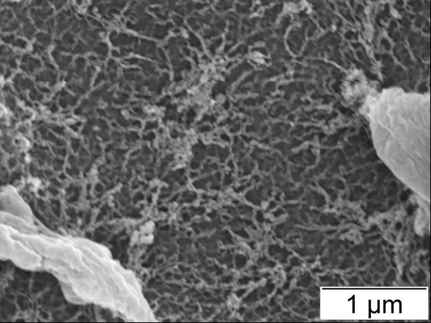
65 (a) (b) (c) (d) (e) Figure 3-7 High-magnification images of the plasma etched (a) PVOH and (b) 1 wt%, (c) 3 wt%, (d) 5 wt%, and (e) 10 wt% CNW / PVOH films. 51
66 In fiber-reinforced composites made by film-casting, the fibers tend to lie down in the films during drying, resulting in an alignment in the 2D plane. The fracture surfaces (cross sections of the films) contain mainly the cross sections of the fibers. Thus observation of the fracture surfaces provides little information on the interaction between the fibers. On the other hand, a direct observation of the film surface shows that there is always a thin layer of polymer on the very top of the films, covering the morphology of the fibers distributed in the bulk material (Figure 3-5a). A brief plasma treatment of the surfaces helps to etch away this thin layer of materials. From Figure 3-5b and 3-5c, it can be seen that the etched surface of the MFC/PVOH films provides further evidence of good dispersion (only the 10 wt% film is shown). Furthermore, it is found that the MFC has formed a web-like structure in the PVOH matrix, which can explain the lower transparency of MFC-based films than that of the CNW-based films. This interconnected fiber network is expected to contribute positively to the improvement of the mechanical properties. On the plasma-etched surfaces of the CNW/PVOH films, there is an increased roughness with increasing filler content (Figure 3-6). While the 1 wt% sample still looks similar to the neat polymer, the composites with higher CNW contents show distinguished irregular features. From the higher magnification images shown in Figure 3-7, it can be seen that there is a large number of small filaments, forming a fishnet structure in the open spaces in the 5 wt% and 10 wt% samples. This morphology resembles the structure of common filter membranes. The size of these filaments is larger than the size of the individual wheat straw CNWs (Figure 2-2 and 2-3 in Chapter 2). One possible interpretation of this morphology is that the cellulose crystals, which 52
67 are more resistant to plasma etching than the polymer, are coated by the polymer that may have melted by the heat generated during plasma treatment. This coat can make the crystals appear bigger and also smoother than they actually are. Another possibility is that the crystals added may have some aggregations at higher filler content, which is not uncommon in polymer nanocomposites Mechanical and thermal properties The viscoelastic behavior of the composite films was investigated by DMA in tension mode. The storage moduli (E ) of the neat PVOH and the composite films are compared in Figure 3-8A and 3-9A. Below the glass transition temperature (T g ) of the polymer, the storage moduli of both the MFC and CNW composite films had noticeable improvement compared with that of the neat PVOH. More prominent improvement was found above the T g. At the same weight content, the MFC-based composites showed even higher modulus than the CNW-based composites. For example, at 85 C, the storage moduli of 5 wt% CNW/PVOH and 5 wt% MFC/PVOH increased by 46% and 88% respectively and those of the 10 wt% CNW/PVOH and 10wt% MFC/PVOH increased by 96% and 240% respectively. The T g of the polymer, as measured by the peaks in tan δ, did not change (58-59 C) with the addition of either MFC or CNW (Figure 3-8b and 3-9b). Above the T g, polymers behave more as a viscous liquid, and their storage modulus drops rapidly. Reinforcement with the stiff MFC and CNWs reduced the magnitude of this drop. 53
68 Log (E' / MPa) a Neat PVOH b 1 wt% CNW c 3 wt% CNW d 5 wt% CNW e 10 wt% CNW 2.5 e d A c a b Temperature ( C) a Neat PVOH b 1 wt% CNW c 3 wt% CNW d 5 wt% CNW e 10 wt% CNW B Tan delta 0.2 a c b e d Temperature ( C) Figure 3-8 DMA of the CNW reinforced PVOH films: (a) Storage moduli (b) Tan δ. 54
69 Log (E' / MPa) 4.5 a Neat PVOH b 1 wt% MFC 4 c 3 wt% MFC d 5 wt% MFC e 10 wt% MFC A a bc Temperature ( C) e d a Neat PVOH b 1 wt% MFC c 3 wt% MFC d 5 wt% MFC e 10 wt% MFC B Tan delta a b c d e Temperature ( C) Figure 3-9 DMA of the MFC reinforced PVOH films: (a) Storage moduli (b) Tan δ 55
70 Figure 3-10 TGA curves of the (a) CNW- and (b) MFC- based composites 56
71 The effects of the cellulose nanoreinforcements on the thermal stability of PVOH were studied by TGA (Figure 3-10A and B). The weight loss of PVOH happened in three steps. The first weight loss, which occurred just above 100 C, is the evaporation of adsorbed water and loosely-bound volatile materials. This was followed by a twostage thermal degradation of the polymer. The major degradation, which started from 3 about 245 C, is the depolymerization of the long polymer chains. In the 2nd stage, which started from about 410 C, the organic compounds were reduced to carbon and hydrocarbons. In both figures, the curves of the composites nearly overlap with those of the neat PVOH. The 10 wt% samples had slightly higher char yield. The addition of the MFC and CNWs did not have noticeable effect on the degradation behavior of the PVOH. 3.4 Model calculations A wide range of micromechanics models are available for predicting the properties of composites based on the properties of the reinforcement and matrix. Models for calculating the elastic modulus of a lamina filled with randomly oriented discontinuous fibers can be very complicated mathematically. A method originally developed by Halpin and Kardos to calculate the modulus of semi-crystalline polymers 4 based on the quasi-isotropic laminate theory is a relatively simple approach. It has been shown that the modulus of a sheet formed by assembling a set of unidirectional (0, 90, ±45, 90, 0 ) laminate is nearly identical with that of a lamina with random 57
72 fiber distribution. Using the stiffness matrix of the stress-strain relationship of this laminate, the elastic modulus of a random lamina can be calculated as: E random = 4U U 5 ( U1 5 ) U 1 where, 1 U 1 = (3Q11 + 3Q22 + 2Q12 + 4Q 8 1 U 5 = ( Q11 + Q22 2Q12 + 4Q 8 with engineering constants: ) ) Q 11 Q 22 = = E 11 ( 1 ν 12ν 21) E 22 ( 1 ν 12ν 21) Q 12 = ν 12Q22 = ν 21Q11 Q 66 = G 12 The longitudinal and transverse moduli, E 11 and E 22, of a lamina reinforced with unidirectional discontinuous fibers are calculated by the Halpin-Tsai equations using the elastic moduli of the fiber and the matrix. 5,6 58
73 Longitudinal modulus: ( ) f L f L f f m V V t l E E η η + = Transverse modulus: f T f T m V V E E η η = 1 22 Shear modulus: 1+ 2 m f G f G G V V G G η η 1+ = = Major Poisson s ratio: ν ν ν ν E E V V f f m m = + = with, ( ) f f m f m f L t l E E E (E / 2 ) / ( 1 ) + = η ) 2( ) / ( 1 ) / ( f f m f m f t w E E E E + T = η 1 ) / ( 1 ) / ( + = m f m f G G G G G η 59
74 where, E f = elastic modulus of fiber E m = elastic modulus of matrix G f = shear modulus of fiber G m = shear modulus of matrix ν f = Poisson s ratio of fiber ν m = Poisson s ratio of matrix ν 21 = minor Poisson's ratio of composite l f = fiber length w f t f = fiber width = fiber thickness. It is assumed that t = w for the CNWs. f f V f = fiber volume fraction V m = matrix volume fraction Because the films made in this study were very thin, the attempt of testing their Young s modulus using a universal testing machine was not successful. During tensile testing, the test specimens either slipped out of one of the grips or fractured near the 60
75 gripping point. Although the storage modulus obtained in the dynamic mechanical analysis is a measurement of the stored energy, it represents the elastic portion of the viscoelastic behavior of polymers and, when tested in tension mode, reflects the material s Young s modulus. Therefore the tensile storage modulus of PVOH in its elastic region (at a temperature about 50 degrees below T g) is used here to calculate the predicted modulus of the composites. A comparison between the predicted and experimentally obtained values will be used to evaluate the mechanical properties of the CNWs. Since both the width and length of the MFC have very large distributions, the aspect ratio of these fibers can not be determined. Thus no model calculations were performed for the MFC-based composites. The storage modulus of PVOH at 0 C, 8.36 GPa, is used as the elastic modulus of the matrix. The wheat straw CNWs are considered as single crystals. The elastic modulus of cellulose I, 138 GPa, is used as fiber modulus. Based on the TEM images of the CNWs (Figure 2-3 in Chapter 2), the fiber aspect ratio (l f / t f ) is calculated as 13. The density of cellulose I β, which dominates in plant cellulose, is The density of 1 PVOH at 40% crystallinity is The Poisson s ratio for the [200]/[004] plane of 8 cellulose I β has been measured to be The Poisson s ratio of PVOH is Using the above parameters, the theoretical moduli of the 1, 3, 5, and 10 wt% CNW composite are estimated using the Halpin-Kardos equations. 61
76 14 12 E' (GPa) Experimental Calculated Weight content of wheat straw CNWs Figure 3-11 Tensile storage moduli of the wheat straw CNW reinforced PVOH composites at 0 C: A comparison between the experimental data and the calculated values. From Figure 3-11, it can be seen that the predicted moduli of the CNW composites agree very well with the experimental values at low fiber content. Adding 3 wt% CNWs improved the polymer s modulus by about 10%. However, at higher filler contents, the curve of the experimental data level off, showing lower values than the predicted. The modulus of the 5 wt% composite was the same as that of the 3 wt% sample and the modulus of the 10 wt% is only slightly higher. In the micromechanics models, it is assumed that the fibers are uniformly distributed throughout the matrix. In reality, this perfect dispersion is usually achieved only at low fiber content. At higher filler content, the effect of the polymer chain conformation resisting fiber dispersion becomes more prominent, making it difficult to achieve the same level of fiber 62
77 distribution. Nonetheless, the modulus of the composites reinforced with wheat straw CNWs matched the values obtained by assuming single crystals is very encouraging. 3.5 Discussion and conclusions The result of the PVOH composites demonstrated that the both the nanofibers (the MFC) and nanocrystals (CNWs) extracted from wheat straw could provide reinforcement in polymer composites. Although the CNWs have higher stiffness than the MFC, which still contains amorphous cellulose, the MFC showed a better reinforcement performance than the CNWs. This can be explained by both the low aspect ratio of the CNWs extracted from wheat straw and the ability of long nanofibers to form an inter-connected web-like structure inside the polymer matrix. The low aspect ratio of the nanowhiskers extracted is due to native wheat straw cellulose crystallites being small. Although all cellulose microfibrils contain crystalline domains, the size of the crystallites in higher plants is much smaller than that of the cellulose crystallites in animals such as tunicates, algae such as Valonia, and bacteria such as Acetobacter. 9,10, 11 For instance, cellulose crystals extracted from tunicates have a width of 10 to 20 nm and a length ranging from 100 nm to several μm. 12 Bacterial cellulose crystals extracted by Grunert and Winter were 50 nm wide, 8 nm thick, and 13 also up to a few μm long. However, cellulose crystals extracted from bleached black spruce Kraft pulp by Revol et al. had an average width of 5 nm and a short length of to 200 nm. The size of the wheat straw CNWs extracted in the present study is also 15 consistent with results published in the literature. 63
78 Secondly, the 13.8% yield of CNWs produced from wheat straw is low. Unlike wood and fiber crops, grass stalks such as wheat straw are not rich in fiber cells, thus lacking the availability of crystalline cellulose. Wheat stem is comprised of a thin layer of epidermis and cortex on the outside, a hollow lumen in the center, and a ring of ground tissue and vascular tissue in between. 16 The thick-walled sclerenchyma cells are rich only in the region below the epidermis, which serves as a boundary to the outside world and provides protection against excessive water loss. The ground tissue consists mainly of large parenchyma cells, which have only thin primary walls. The microfibrils in the 17 primary cell wall have a low content of crystalline cellulose. This explains the low yield of CNWs from wheat straw. On the other hand, it has been shown that cellulose microfibrils can be extracted not only from fiber cells, but also from the primary walls of 18 parenchyma cells. Although individual microfibrils may not be as stiff as cellulose crystals, their large aspect ratio compensates for the low modulus and provide better reinforcement in polymer composites than do cellulose crystals. Furthermore, the process of extracting the nanofibers is also shorter and less costly than that of extracting the CNWs. The costs of producing CNW and MFC using current technologies in a production plant have been estimated and presented in Appendix C. Based on this estimate, the CNW is at least five times more expensive than the MFC to produce due to higher demand in capital investment. Therefore, when biomass such as wheat straw is used as a raw material, the nanofibers appear to be a better value-added polymer reinforcement material than the CNWs. 64
79 Although water-soluble polymers are convenient matrix materials to fabricate cellulose nanocomposites, the difficulty of making bulk samples with these polymers and their high sensitivity to humidity make it difficult to evaluate many important properties of these nanoreinforcements. In addition, since PVOH is mainly used as emulsifying aid, textile sizing agent, and adhesives, the need for higher stiffness is often not demanded. In the next chapter, the opportunities of using the cellulose nanofibers extracted from wheat straw in strengthening structural materials will be explored. 65
80 References 66
81 References 1 Pritchard, J. G., Poly(vinyl Alcohol): Basic Properties and Uses. Polymer Monographs, v. 4., Gordon and Breach Science Publishers, London, UK, Chiellini, E., Corti, A., D'Antone, S., and Solaro, R., Biodegradation of poly (vinyl alcohol) based materials, Progress in Polymer Science, 2003, 28(6), Tsuchiya, Y., and Sumi, K., Thermal decomposition products of poly(viny1 alcohol), Journal of Applied Polymer Science, Part A: Polymer Chemistry, 1969, 7(11), Halpin, J. C., and Kardos, J. L., Moduli of crystalline polymers employing composite theory, Journal of Applied Physics, 1972, 43(5), Halpin, J. C., and Kardos, J. L., The halpin-tsai equations: A review, Polymer Engineering and Science, 1976, 16(5), Mallick, P. K., Fiber-Reinforced Composites: Materials, Manufacturing and Design, Mercer Dekker, Inc. New York, Ganster, J., and Fink, H.-P., Physical Constants of Cellulose, in Polymer Handbook, 4th Edition, edited by Brandrup, J., Immergut, E. H., Grulke, E. A.., Abe, A., and Bloch, D. R., John Wiley & Sons, New York, Nakamura, K., Wada, M., Kuga, S., and Okano, T., Poisson's Ratio of Cellulose Iβ and cellulose II, Journal of Polymer Science, Part B: Polymer Physics, 2004, 42(7), Ranby, B, Morphology of native cellulose related to the biological synthesis, Cellulose Chemistry and Technology, 1997, 31(1-2), Kuga, S., and Brown Jr., R. M., Lattice imaging of ramie cellulose, Polymer Communications, 1987, 28(11), Earl, W. L, and VanderHart, D. L., Observations by high-resolution carbon-13 nuclear magnetic resonance of cellulose I related to morphology and crystal structure, Macromolecules, 1981, 14(3),
82 12 Favier, V., Chanzy, H., and Cavaille, J. Y., Polymer nanocomposites reinforced by cellulose whiskers, Macromolecules, 1995, 28(18), Grunert, M. and Winter, W. T., Nanocomposites of cellulose acetate butyrate reinforced with cellulose nanocrystals, Journal of Polymers and the Environment, 2002, 10(1/2), Revol, J.-F., Bradford, H., Giasson, J., Marchessault, R. H., and Gray, D. G., Helicoidal self-ordering of cellulose microfibrils in aqueous suspension, International Journal of Biological Macromolecules, 1992, 14(3), Helbert, W., Cavaille, J.Y., and Dufresne, A., Thermoplastic nanocomposites filled with wheat straw cellulose whiskers. Part I: processing and mechanical behavior, Polymer Composites, 1996, 17(4), Yu, H., Liu, R., Shen, D., Wu, Z., and Huang, Y., Arrangement of cellulose microfibrils in the wheat straw cell wall, Carbohydrate Polymers, 2008, 72(1), O Sulliva n, A. C., Cellulose: the structure slowly unravels, Cellulose, 1997, 4(3), Dinand, E., Chanzy, H., and Vignon, M. R., Parenchymal cell cellulose from sugar beet pulp: Preparation and properties, Cellulose, 1996, 3(3),
83 CHAPTER 4 MFC REINFORCED POLYLACTIC ACID NANOCOMPOSITES 4.1 Motivation The attractiveness of biobased nanoreinforcements is enhanced when they can be combined with a biobased polymer resin. The biocomposites thus obtained will be completely renewable and biodegradable. Biodegradable polymers can be broadly divided into two categories: biopolymers from renewable resources and petroleumbased synthetic polymers that are biodegradable such as PVOH. Biopolymers from renewable resources can be further classified into three groups: (1) natural polymers such as cellulose, chitosan and starch; (2) synthetic polymers made from renewable raw materials such as poly(lactic acid) (PLA); and (3) microbially synthesized biopolymers such as polyhydroxyalkanoates (PHAs). 1,2 Although there are many biopolymers, PLA has been considered as one of the most promising candidates for a wide range of applications thanks to its high modulus, relatively low moisture sensitivity, and proven biocompatibility. 3,4 Currently, the major obstacle for the wide-spread adoption of PLA to replace petroleum-based commodity plastics is its high cost. However, the price of PLA has been falling in recent years as production increases and technology advances. 69
84 Improvement in the material properties of this polymer is also desired before it can gain wider commercial applications. The polymer s inherent brittleness, low impact strength, poor thermal resistance, and slow crystallization rate are the major disadvantages that make this polymer less competitive when compared to conventional commodity plastics. Combining cellulose nanofibers and PLA may yield green composites with improved mechanical properties for wider applications. Furthermore, the biocompatible nature of both PLA and cellulose offers exciting opportunities for these composites being used in the biomedical field. In this chapter, both the need for and the challenges in the development of PLA nanocomposite will be discussed first. A new water-based processing route is proposed to solve the difficult problem of dispersing the hydrophilic cellulose nanofibers into PLA. The PLA nanocomposites prepared with this method will then be studied. 4.2 Background Introduction to PLA PLA is an aliphatic polyester that can be derived from renewable resources and is biodegradable. It is a polymer of lactic acid (2-hydroxypropanoic acid, C 3 H 6 O 3 ), which is a hydroxycarboxylic acid naturally present in humans and animals. In industry, lactic acid is produced by chemical synthesis or bacterial fermentation from sugarcontaining materials such as corn starch, potato starch, and sugarcane. 5,6 Compared with chemical synthesis, microbial fermentation has the advantages of high product 70
85 specificity, low energy consumption, and environmental friendliness. Lactic acid is a chiral molecule, existing as two stereoisomers, L-lactic acid and D-lactic acid. Conversion of lactic acid into high-molecular-weight PLA can be achieved by two methods. The first method is the direct polycondensation of lactic acid. Since the presence of water generated in the esterification reaction hinders chain growth, until very recently only very low-molecular-weight polymers could be produced by this method. In the 1990s, Mitsui Toatsu Chemicals in Japan patented a process to remove the condensation water by azeotropic distillation using organic solvents. 7 Another effective way of achieving high molecular weight is to use chain extenders to link the low-molecular-weight prepolymer after the condensation reaction. 8 The more wide-spread method of manufacturing high-molecular-weight PLA today is through the ring-opening polymerization of an intermediate compound called lactide. Lactide (C 6 H 8 O 4 ) is a cyclic di-ester formed by two molecules of lactic acid. In the first step of this process, lactic acid is oligomerized and then catalytically depolymerized to lactide through a back-biting transesterification reaction. Water generated in the oligomerization is removed prior to polymerization. Because the lactic acid molecule is chiral, three different stereoisomers of lactide exist: D,D-lactide, L,Llactide, and meso-lactide. The catalyzed ring-opening polymerizations of D,D-lactide and L,L-lactide lead to the synthesis of poly-d-lactide (PDLA) and poly-l-lactide (PLLA) respectively. In addition, the polymerization of a racemic mixture of D,D- and L,Llactides yields poly-dl-lactide (PDLLA), which, unlike PLLA and PDLA, is not semicrystalline but amorphous. NatureWorks LLC, a wholly owned subsidiary of Cargill, is 71
86 the largest producer of PLLA in the world. PURAC, a Dutch company owned by CSM, is the primary producer of PDLLA. As a thermoplastic, PLA can be melt processed into fibers, films and various molded articles. Although the process of making PLA has been known for almost a century, this polymer did not attract too much commercial interest in the past mainly due to its high production cost and inferior thermal properties compared to petroleum-based plastics. In recent years, advances in fermentation and polymerization technologies have lowered the price of PLA considerably. Development in the material science of PLA has also helped to improve its mechanical and thermal properties. The fact that PLA is biodegradable and can be produced from renewable resources makes the polymer an attractive environmentally friendly alternative to conventional commodity plastics. Increased demand for PLA products has led to fast growth in its production around the world in the last decade. Higher production volume in turn is driving its production cost down even further The need for PLA composites PLA has entered many areas of applications including packaging, paper coating, biomedical products such as sutures and drug delivery devices and consumer goods such as toys and cold beverage bottles. PLA composites are mainly needed in the following two areas. 72
87 Applications in structural materials Although PLA has relatively high modulus, it is known to be extremely brittle. In other words, PLA is strong but not tough. The low toughness of PLA hinders its applications in structural materials such as automotive parts and housings of portable electronic devices. Different approaches such as adding plasticizers, block copolymerization, blending with rubber or tougher polymers have been proposed to toughen PLA. These often lead to decreases in the modulus and strength of the polymer. Adding high-aspect-ratio cellulose nanofibers may toughen the PLA matrix by a bridging mechanism. And thanks to the high Young s modulus of the nanofibers, the polymer may become both tougher and stronger, which is often highly desirable. Furthermore, for semi-crystalline PLA, adding cellulose nanofibers and nanowhiskers is expected to change its crystallization behavior. Nanoparticles and nanofibers have been shown to act as nucleating agents for thermoplastics. 9 The incorporation of cellulose nanoreinforcements may lead to faster crystallization rate, higher crystallinity and smaller spherulite size of PLA, which may further improve the polymer s mechanical properties. Applications in the medical field Thanks to its proven in vivo biocompatibility, PLA has already enjoyed successful clinical use as carriers for controlled drug release and as resorbable sutures and bone screws and pins for temporary internal fixation. Since PLA has relatively high stiffness and longer degradation time compared with other biodegradable polymers, extensive studies have been done in the last 30 years to evaluate the potential of expanding PLA 73
88 applications as an absorbable alternative to conventional metallic implant materials in tissue engineering and orthopaedic surgery. 10 However, to be used effectively as stents, scaffolds, and load-bearing implants for hard tissues such as cortical bone, the mechanical properties of PLA have to be further improved. 11,12, 13 The Young s moduli of cortical bone in the longitudinal and tangential directions are 17.7 GPa and 12.8 GPa respectively and the strengths in the two directions are 133 MPa and 52 MPa respectively. 14 A comparison of the flexural modulus and strength of PLLA and those of the commonly used implant materials and cortical bone is shown in Table 4-1. Table 4-1 Flexural properties of PLLA 15 compared with those of commonly used implant materials and human cortical bone 16 Flexural modulus Flexural strength Fiber (GPa) (MPa) PLLA Cortical bone Stainless steel Cobalt chromium alloy Titanium alloy The inferior mechanical properties of PLA compared with cortical bone and permanent metallic implant materials have limited its use mainly in soft tissue fixations. On the other hand, metal plates and screws that have been used in hard tissue 74
89 applications have several disadvantages including the need for removal after healing, corrosion, and the release of metal ions, which causes inflammatory and allergic reactions. Most importantly, the very high modulus of metals causes insufficient load bearing of the bone. This stiffness mismatch between the bone and the implant is known as stress shielding or stress protection, which retards bone healing process and increases bone porosity. 17 Although the low modulus of absorbable polymers may help to prevent stress shielding, they have not been used in hard tissue applications mainly because of their insufficient strength. Fiber-reinforced polymer composites have a great potential solving these problems. By reinforcing with fibers, the strength of the polymers can be improved. In addition, the properties of the composites can be tuned by varying fiber volume fractions to meet the specific clinical conditions. The requirements of cell compatibility and biodegradability limit the choice of fibers that can be used in these applications. The use of carbon nanotubes, phosphate glass fibers, and silk have been explored. 18,19, 20 However, the most satisfactory results have been obtained by self-reinforcing high-molecular-weight PLA with oriented PLA fibers, first developed by researchers in Finland in the early 1990s. 21,22 The bending modulus and strength of the self-reinforced (SR) PLA rods achieved range from 8 GPa to 10 GPa and 245 MPa to 300 MPa respectively. * The biocompatibility of cellulose is also well established. 23 Bacterial cellulose and regenerated cellulose have * The SR-PLA technology was commercialized by Bionx Implants, Inc. in Finland in the late 1990s. The company has been purchased by ConMed Corporation (Utica, NY). 75
90 found clinical uses in wound healing devices and are also been evaluated as a potential scaffold material for tissue engineering. 24,25 The following are the proposed advantages of reinforcing PLA implants with cellulose nanofibers. (1) Increased stiffness and strength. The ability of the nanofibers to form a network structure is expected to improve the strength of PLA greatly. (2) PLA looses its strength during degradation, leading to a gradual transfer of load from implant to the bone, which is beneficial for new bone formation. However, in some cases, a longer strength retention time is desired for healing. The in vivo degradation of cellulose takes much longer time. 26 Thus cellulose nanofibers can maintain the stability of fracture fixation after PLA degradation. (3) It has been reported that the degradation products of cellulose may promote cellular proliferation. 27 (4) In addition to fibers, naturally occurring ceramic materials such as hydroxyapatite (HA) and tricalcium phosphate (TCP) are often added to resorbable polymers to enhance bone growth. 28 Cellulose nanofibers may work as good carriers for these materials Challenges in PLA nanocomposite fabrications As discussed in Chapter 1, achieving good dispersion of cellulose in a non-watersoluble polymer matrix has been a major obstacle in the development of cellulosebased nanocomposites. Different processing routes can be considered for incorporating cellulose into PLA. 76
91 Direct mixing In this approach, cellulose water suspensions are mixed directly into PLA melt in an extruder. Water removal takes place in the extruder by evaporation. Mixed results have been published on the quality of dispersion by this method. Chakraborty et al. reported good dispersion of microfibrils in PLA at low fiber content. 30 However, Oksman et al. found that feeding MCC water dispersion directly into the extruder caused agglomeration of cellulose in the polymer matrix as well as some thermal degradation. 31 Solution-casting approach PLA can be dissolved in selected organic solvents such as dichloromethane, chloroform, and dimethylformamide (DMF). In this approach, CNW or MFC is first transferred from water to an appropriate organic solvent either by solvent exchange or by drying and re-dispersing, and is then mixed with PLA dissolved in the same solvent. The volatile solvent can then be easily removed by evaporation. Solvent exchange is a lengthy and expensive process, especially considering that the cellulose content in the original water suspension is often very low. Cellulose fibers always tend to aggregate by hydrogen bonding when dried and the resulting high force of attraction between them makes re-dispersion in other solvents and even in water difficult, which then leads to poor dispersion in the polymer matrix
92 Mixing before polymerization Since the lactide used in the ring-opening polymerization of PLA is water soluble, it is possible to mix MFC and CNW with lactide in water before polymerization takes place. However, the difficulty of carrying out the polymerization reaction in a water medium and the harsh conditions involved in it make this route rather impractical. Funabashi and Kunioka prepared cellulose fiber filled PLA composites by mixing dry cellulose fibers with L-lactide before ring-opening polymerization, and the results showed decreasing molecular weight and elastic modulus with increasing fiber content Summary of the water-based processing route Although PLA cannot be dissolved in water, if it is dispersed in water as colloids and if the size of the colloids is small enough to be comparable to the dimension of the cellulose nanofibers, it is reasonable to expect good mixing of the two components in a water suspension. In the pharmaceutical industry, PLA and poly(lactic-co-glycolic acid) (PLGA) are among the most popular substrates for controlled drug release. The drug substances are usually encapsulated in polymer microspheres by a well-established method called emulsion solvent evaporation technique. 34 Depending on the specific needs, very small microspheres can be prepared with this method. Microspheres with diameters less than 200 nm (thus also called nanospheres) have been obtained. 35,36 78
93 A water-based processing route using PLA colloids may lead to good dispersions in cellulose-reinforced PLA nanocomposites. The two most important tasks of this approach are: to prepare a PLA colloidal suspension with reasonable stability and to find a drying method that can maintain the dispersed state Colloidal suspension of PLA microspheres In the emulsion solvent evaporation process, the polymer is first dissolved in a volatile water-immiscible organic solvent. The resultant solution (the oil phase) is then emulsified into a continuous water phase to form discrete oil droplets. This is normally achieved by adding a suitable surfactant and by using a high-speed mixer. The organic solvent is then evaporated from the emulsion under stirring to let the oil droplets harden to form microspheres. Important variables that affect the solvent evaporation process include polymer molecular weight and crystallinity, organic solvent used, surfactant chemistry, surfactant concentration, solvent-to-water ratio, and the mixing method and 37 speed. PDLLA Since lactic acid is a chiral molecule, three different forms of PLA, namely PLLA, PDLA, and PDLLA, are available. Compared with the amorphous PDLLA, the semicrystalline PLLA has higher stiffness and strength, and better impact and heat 3 resistance. 8 On the other hand, PDLLA has a faster in vivo degradation rate than both the amorphous and semi-crystalline PLLA and is thus often preferred in biomedical 79
94 applications. 39,40 Furthermore, the addition of nanofillers may change the crystallization behavior of semi-crystalline polymers, which then lead to changes in the mechanical properties. By choosing the amorphous PDLLA as the matrix material, the assessment of the reinforcing performances of the cellulose nanofibers does not need to consider the factor of changed crystalline structure of the polymer. The nucleating effect of these nanofillers on the polymer s crystallization behavior will be investigated in future studies. Solvent Solvents with high volatility and low water solubility are preferred in the solvent evaporation technique. The amorphous PDLLA can be dissolved in chloroform, dichloromethane (methylene chloride), tetrahydrofuran (THF), dimethylformamide (DMF), ethyl acetate, or acetone. Ethyl acetate is chosen in the present work because of its relatively high vapor pressure and its low toxicity compared with other organic solvents. Surfactant Various surfactants can be used for producing PLA microspheres. The type and concentration of the surfactant selected can affect the effectiveness of the emulsification process and the particle size and zeta potential. Partially hydrolyzed PVOH has been proven most effective in stabilizing PLA and PLGA emulsions, hence has been widely used in the pharmaceutical industry for drug encapsulation. 41 However, since PVOH is immiscible with PLA in melt processing, a suitable surfactant has to be found. Common 80
, glycolic acid ethoxylate 4-tert-butylphenyl ether (GAEBPE), and Polysorbate 80 (commercially known as TWEEN 80) were tested (Appendix D).")

95 surfactants and electrolytes such as sodium dodecyl sulfate (SDS), high-molecularweight polyacrylic acid, Triton X-100, sodium polystyrene sulfonate (PSS), glycolic acid ethoxylate 4-nonylphenyl ether (GAENPE), glycolic acid ethoxylate 4-tert-butylphenyl ether (GAEBPE), and Polysorbate 80 (commercially known as TWEEN 80) were tested (Appendix D). The Polysorbate 80 was found to have the highest emulsification capabilities in this system. Polysorbate 80 is a nonionic surfactant derived from polyethoxylated sorbitan and oleic acid (Figure 4-1). It is often used in pharmaceuticals, cosmetic products, and foods because it has been approved by the FDA for human consumption. Since one of the targeted applications of the cellulose nanocomposites is in the medical field, the biocompatibility of polysorbate 80 also makes it a suitable choice. Figure 4-1 The chemical structure of Polysorbate 80 81
96 4.3.2 Water removal after mixing Although the cellulose nanofibers and PDLLA can be mixed in water, since there is no strong interaction between them, a suitable water-removal method has to be found to prevent de-mixing during drying to ensure good dispersion in the final product. This was found to be a difficult task. Various drying methods were tried, including freeze drying, membrane filtration, centrifugation, and spray-drying. None of them provided completely satisfactory results (details can be found in Appendix E). As shown in Appendix E, membrane filtration can not prevent partial de-mixing of the MFC and PLA microspheres regardless of filtration speed, volume, filter chemistry, and pore sizes. During filtration, as the water is drawn away, the MFC forms a gel, trapping the PDLLA microspheres. This gel is only capable of catching a fraction of all the microspheres, leading to the formation of a separate MFC-rich sheet in the filtration products. These paper-like sheets are formed by the MFC network locking PLA microspheres, preserving the mixed state of the two components. On the other hand, the PLA layer is formed by dried PLA microspheres loosely packed together, lacking any structural integrity. Thus it is possible to separate the MFC-rich sheets from the filtration products by carefully chipping the PLA flakes away. These MFC-rich sheets can then be used for compression molding. Processing at an elevated temperature changes the microspheres into a viscous liquid, which is then cooled down to form the continuous phase in the final composites. 4.4 Experimental details Materials 82
97 The poly(lactic acid) used in this study was PURASORB PDL 04 purchased from PURAC America, Inc. (Lincolnshire, IL). It is a poly(dl-lactide) product manufactured for drug delivery systems. The inherent viscosity midpoint was 0.39 dl/g tested at 1.0 g/dl in chloroform. The weight average molecular weight was approximately 45,000 g/mol. Wood cellulose fibers used were CreaTech TC90 fibers provided by CreaFill Fibers Corp. (Chestertown, MD). The TC90 fibers are pure alpha cellulose (99.5%) and their average width and length are 20 μm and 60 μm respectively. Polysorbate 80 (a.k.a. Tween 80) was purchased from Sigma-Aldrich Co. (St. Louis, MO). Ethyl acetate (99.99%), manufactured by EMD Chemicals Inc. (Gibbstown, NJ), was used as received. The Mixed Cellulose Esters (MCE) membrane filters and Millipore Durapore PVDF membrane filters were purchased from Advantec MFS Inc. (Dublin, CA) and Fisher Scientific (Pittsburgh, PA) respectively. Fiber preparation Wood MFC was produced from CreaTech TC90 cellulose fibers. The as-received fibers were dispersed in RO water at 4 wt% by using a kitchen blender and then treated with a Mini DeBEE Ultra-High Pressure Homogenizer (BEE International, South Easton, MA). The sample was first homogenized with a inch nozzle at 16,000 psi (110 MPa) for 4 passes and then with a inch nozzle at about 42,000 psi (290 MPa) for 20 passes. A creamy colloidal suspension was obtained. The procedure for pulping wheat straw was the same as described in Chapter 2. Briefly, the -42/+60 mesh wheat straw powder was treated with 10 wt% peracetic acid at 90 C for 30 min and washed with warm water and a warm ethanol/acetone mixture 83
98 (about 50 C). The sample was then treated with 17.5 wt% NaOH/water solution at 25 C for 30 min before being diluted with an equal amount of water and treated for another 30 min. The α-cellulose thus obtained was homogenized following the same procedure as in the wood MFC preparation. Since the DeBEE homogenizer operates at a much higher pressure than the APV-1000 homogenizer used in Chapter 2, a better defibrillation effect was expected. The size and morphology of the nanofibers produced were studied by using a JEOL 100CX transmission electron microscope (TEM) operated at 100 kv. The specimens were prepared by sonicating a dilute suspension for about 30 sec and depositing a tiny drop on Formvar carbon grids. The samples were first observed directly and then stained with 1 wt% uranyl acetate water solution for about 4 min. Preparation of PDLLA microspheres The PDLLA granules were dissolved in ethyl acetate (10 wt%) by stirring at room temperature. Polysorbate 80 was dissolved in water by mixing with the IKA Ultra-Turrax T 25 homogenizer (IKA Works, Inc., Wilmington, NC) equipped with a S25N-25F dispersing element at 8,000 rpm for 5 min. The PDLLA solution was then emulsified into the polysorbate water solution by homogenizing with the Ultra-Turrax T 25 homogenizer at 10,000 rpm for 10 min. The emulsion was then sonicated with the Cole-Parmer 750- Watt Ultrasonic Processor (Cole-Parmer, Vernon Hills, IL) at 100 W for 2 min. Solvent evaporation was then carried out by heating in a 40 C water bath overnight. A milky colloidal suspension was obtained. 84
99 The weight content of the suspension was determined by heating one drop of the suspension to constant weight at 105 C using a TA Instruments Thermal Gravimetric Analyzer ( TGA) Model Q500 (TA Instruments, New Castle, DE). The yield of microspheres was then calculated by dividing the total weight of microspheres suspended in water by the initial weight of the polymer and surfactant. The morphology of the microspheres produced was observed with a JEOL JSM Scanning Electron Microscope (SEM) operated at 10 kv. A few drops of the colloidal suspension were filtered onto a 0.1 μm pore size MCE filter membranes and air dried. The filter membranes were used as carriers for the microspheres. The samples were then made conductive by gold coating for 2 min (Gold deposition was about 7nm per min). Nancomposite fabrications Three PDLLA composites were prepared using the wood nanofibers. Their weight contents were later calculated to be 8%, 15%, and 32%, respectively. Limited by the amount of nanofibers extracted from wheat straw, only one composite (32 wt%) was made using wheat straw MFC. Mixing and filtration The pre-determined amounts of MFC and PDLLA water suspensions were mixed for 1 h by stirring and filtered with 0.65 μm pore size Durapore membrane filters. The PDLLA loaded was always in excess to compensate for the weight loss after layer separation. Because the MFC-rich sheets were thin when the weight contents of MFC 85
100 were low, in order to keep the volume in each filtration run and hence the filtration time roughly the same, multiple sheets (5 to 6) were made for the 8wt% and 15 wt% samples for being assembled later. In the case of the two 32 wt% samples (wood MFC and wheat straw MFC), the whole mixtures were filtered in just one batch. A neat PDLLA sample was also prepared by filtering PDLLA colloidal suspensions. The sample cakes collected were sandwiched between blotting papers and air dried slowly. Light weight was applied on top to prevent curling up. After drying, all sample cakes had a two-layer structure comprised of a MFC-rich sheet on the top and PDLLA layer on the bottom. The MFC-rich sheets were carefully separated from the PDLLA layers and were used for compression molding. Compression molding The molds used for compression molding were 1.4 mm thick stainless steel plates with round cavities cut out in the middle. Due to the shrinking of cellulose, the diameter of the sample cakes became smaller with higher MFC content. Thus each sample was molded using a mold with a cavity diameter about the same as that of the sample sheet. Compression molding was carried out on a Carver Laboratory Press (Carver, Inc., Wabash, IN) at 105 C and 90 psi (0.6 MPa). Vacuum bag was used to prevent the creation of voids. It was assumed that there was no fiber loss during filtration and all the MFC was concentrated in the MFC-rich sheets after filtration. The weight contents of MFC in the final composites were calculated by dividing the initial weight of MFC loaded by the weight of the discs obtained by compression molded. 86
101 Evaluation of dispersion and adhesion The fracture surfaces created by flexural testing were imaged with the JSM-6400 SEM. The samples were gold coated for about 2 min (7 nm/min) before being observed. Thermal and mechanical property characterizations The flexural properties were measured following the ASTM D790 standard using a universal testing machine (Model SFM-20, United Calibration Corp, Huntington Beach, CA). The 0.5 inch (12.7 mm) wide specimens were cut out from the compression molded discs and conditioned in 50 % relative humidity at room temperature for at least 40 h before being tested. The samples were tested to failure at a span distance of 1 inch (25.4 mm) and crosshead speed of 0.03 inch (0.762 mm) per min. The flexural modulus was calculated by using the slope of the steepest initial straight-line portion of the stress-strain curve. The flexural strength was the maximum stress before failure. The dynamic mechanical analysis (DMA) was performed in 3-point bending mode on a TA Instruments Dynamic Mechanical Analyzer Model Q800. Test specimens were about 8 to 12 mm wide and 1.4 mm thick and were also conditioned in 50 % relative humidity at room temperature for about 40 h. The support span, frequency, and amplitude of oscillation were set at 20 mm, 1 Hz, and 70 μm respectively. Temperature scans were from 20 C to 105 C at a heating rate of 3 degrees per min (The testing of 87
102 the neat PDLLA and the composites with low fiber contents had to be terminated early due to their excessive deformation above T g ). The thermal stability of the samples was studied with TA Instruments TGA Model Q500. A small amount of sample (10-20 mg) was heated from room temperature to 580 C at 10 degrees per min under nitrogen purge. 4.5 Results Nanofibers obtained from wood and wheat straw The MFC produced from wood cellulose fibers and the MFC extracted from wheat straw have very similar morphologies, with the wheat straw MFC looks finer (Figure 4-2). The extraction of wheat straw MFC followed the same procedure as in Chapter 2 except a homogenizer that operates at a higher pressure was used. This has led to a reduction in the fiber width distribution. From higher-magnification images in Figure 4-3, it can be seen that the width of individual microfibrils has remained the same PDLLA microspheres By using the solvent evaporation technique, the water-insoluble PDLLA was dispersed in water as microspheres (Figure 4-4). It can be seen that, although the size of the microspheres is not uniform, the majority of them are nanoparticles. These microspheres appeared perfectly spherical when being observed. During image 88


103 collection, the shape of some microspheres changed due to electron beam degradation. The average yield of the microspheres is about 92%. (a) (b) 89
 wood MFC and")
 (b) 90")
104 Figure 4-2 A comparison of the (a) wood MFC and (b) MFC extracted from wheat straw (a) (b) 90

105 Figure 4-3 TEM micrographs of wheat straw MFC negatively stained with 1 wt% uranyl acetate. Image in (b) is a close-up image showing individual microfibrils. Figure 4-4 PDLLA microspheres produced by using the emulsion solvent evaporation technique Evaluation of dispersion and adhesion The neat PDLLA sheet produced by compression molding was clear, while the composites were opaque with an off-white color. An examination of the fracture surfaces of the composites shows excellent dispersion of the MFC (Figure 4-5). Individual microfibrils are found on all the surfaces. No large aggregates can be seen. On the other hand, since these surfaces were 91


 8wt%, (b) 15wt%, and (c) 32")
106 created by flexural testing, a large number of fibers pulling out from the fracture surfaces also indicate that there is no good adhesion between the fiber and the matrix. This is expected since no compatibilizers have been added in these experiments to enhance the affinity between the hydrophilic cellulose and the hydrophobic PDLLA. (a) (b) (c) (d) Figure 4-5 Fracture surfaces of the composites reinforced with (a) 8wt%, (b) 15wt%, and (c) 32 wt% wood MFC, and (d) 32wt% wheat straw MFC 92
107 4.5.4 Mechanical properties of the PDLLA composites The flexural properties of the PDLLA composites reinforced with wood MFC were compared to those of the neat PDLLA (Figure 4-6). Both the flexural modulus and strength increased with increasing MFC content. The composite reinforced with 32 wt% MFC exhibited increases in flexural modulus and strength of 60% and 209% respectively. As discussed earlier in this chapter, a higher strength for PLA is highly desired in its potential biomedical applications. Although no reliable data is available on the strength of cellulose microfibrils, the mechanical properties measured for the plant cell wall and various plant stems suggest high strength characteristics for these nanofibers. In addition, their high aspect ratio and their strong tendency to entangle through hydrogen bonding contribute greatly to the strength enhancement of the polymer. The storage moduli of the composites were also higher throughout the temperature range tested compared with that of the neat polymer (Figure 4-7). The storage modulus of the 32 wt% composite was about 67% higher than the PDLLA at 25 C. More importantly, while the amorphous PDLLA lost its structural integrity quickly after the temperature rose above its T g, the cellulose nanofibers were maintaining the stiffness of the composite samples. Even at a temperature above 100 C, the modulus of the 32 wt% composite was still above 1 GPa. This shows clearly the ability of the cellulose nanofiber networks to bear load. Furthermore, the T g measured by the 93
108 midpoint of the drop on the storage modulus curves was about 3 degrees higher for the composites Flexural modulus (GPa) Weight content of wood MFC a 94
109 100.0 Flexural strength (MPa) b Weight content of wood MFC Figure 4-6 Comparison of the (a) flexural modulus and (b) strength of the neat PDLLA and the wood MFC reinforced composites 95
110 Storage modulus (GPa) d c b a a Neat PDLLA b 8 wt% MFC/PDLLA c 15 wt% MFC/PDLLA d 32 wt% MFC/PDLLA Temperature ( C) Figure 4-7 Comparison of the storage moduli of the neat PDLLA and the wood MFC reinforced composites Effectiveness of MFC extracted from wheat straw The effectiveness of MFC extracted from wheat straw compared with that of the wood MFC was then assessed. The flexural modulus values tested for the 3 specimens of the 32 wt% wheat straw MFC composite agreed very well with each other. However, one of the specimens fractured at a much lower strain than the other two, resulting in a much lower strength measured for this specimen (Table 4-2). A microscopic examination of the fracture surface showed that there was a large defect right at the edge of this specimen (Figure 4-8). It could not be determined whether this was an 96

 (MPa) (%) 1 5.")
111 aggregate of the MFC. Since the test specimens were only about 1.4 mm thick, a defect of this size could cause immature failure of the specimens. Based on the above analysis, it is proposed that this data point be rejected in the strength calculation. Thus the flexural modulus reported for this sample is the average of three tests while the flexural strength is the average of just two tests. Table 4-2 Testing results of the flexural properties of the 32 wt% wheat straw MFC reinforced PDLLA composite Flexural modulus Flexural strength Strain at fracture Test specimens (GPa) (MPa) (%) (a) (b) Figure 4-8 SEM images showing the defect at the fracture surface of the 2nd test specimen in table 2. (a) An overview and (b) a close-up image of the defect 97
112 a Flexural modulus (GPa) Neat PDLLA 32wt% wood MFC 32wt% wheat straw MFC b Flexural strength (MPa) Neat PDLLA 32wt% wood MFC 32wt% wheat straw MFC Figure 4-9 A comparison of the (a) flexural modulus and (b) strength of the PDLLA reinforced with wheat straw MFC and wood MFC 98
113 Storage modulus (GPa) b c a a Neat PDLLA b 32 wt% wood MFC c 32 wt% wheat straw MFC Temperature ( C) Figure 4-10 A comparison of the storage moduli of the 32wt% wheat straw MFC / PDLLA and wood MFC / PDLLA. From the comparison of the flexural properties shown in Figure 4-9, it can be seen that the wheat straw MFC improved the stiffness and strength of PDLLA to a similar magnitude as the wood MFC. The modulus of the 32 wt% wheat straw MFC composite is 51% higher than that of the neat PDLLA, and about 6% lower than that of the wood MFC composite. The storage modulus curves of the two composite samples look almost identical, with the wheat straw MFC curve shifting about 0.4 GPa downwards (Figure 4-10). 99
114 4.5.6 Comparison of thermal stabilities The thermal stabilities of the nanocomposites were compared to those of the asreceived PDLLA and the control sample (Figure 4-11). The decomposition of the asreceived PDLLA started at about 240 C. This value agreed well with the decomposition temperature of PDLLA reported in the literature. 42 On the other hand, there was no significant weight loss for the control sample and the composites below 300 C, with the decomposition temperatures of the two 32 wt% samples slightly lower. The heat treatment during compression molding may have removed some volatile components of the polymer and increased the interaction between the polymer chains, resulting in better thermal stabilities. Since the thermal decomposition temperature of cellulose is slightly lower than that of PLA, with more cellulose nanofibers added, the onset decomposition temperature of the composites also became slightly lower. 100
115 Weight % wt% wood MFC PDLLA (as-received) 32wt% wheat straw MFC PDLLA (control) and the 8wt% and 15wt% composites Temperature ( C) Figure 4-11 Comparison of the thermal stabilities of the PDLLA and the MFC/PDLLA composites 4.6 Discussion and conclusions By using a water-based processing route, PLA composites were prepared with excellent dispersions of the cellulose nanofibers. It was shown that once good dispersion was achieved, the nanofibers were able to improve both the stiffness and strength of the polymer. The increase in the strength was especially pronounced. The flexural strength of the 32 wt% composites was more than 200% higher than that of the neat PLA. High-strength biocompatible materials are urgently needed in making resorbable medical devices. 101
116 Limited by the amount of materials available, only one composite was prepared with the nanofibers extracted from wheat straw. This 32wt% composite showed similar properties with the composite based on wood nanofibers. Since most of the investigations on cellulose nanofibers from biomass have been limited to study their properties in thin films, this result shows favorably the potential of biomass being used as a low-cost feedstock for cellulose nanofiber productions. Currently only a fraction of the PLA microspheres loaded at the beginning can be trapped in the cellulose network and used for composite making. Improved stability of the PLA microspheres and surface modifications that enhance affinity between cellulose and PLA are possible approaches to further improve this method. 102
117 References 103
118 References 1 Yu, L., Dean, K., and Li, L., Polymer blends and composites from renewable resources, Progress in Polymer Science, 2006, 31(6), Satyanarayana, K. G., Arizaga, G. G. C., and Wypych, F., Biodegradable composites based on lignocellulosic fibers-an overview, Progress in Polymer Science, 2009, 34(9), Van de Velde, K., and Kiekens, P., Biopolymers: Overview of several properties and consequences on their applications, Polymer Testing, 2002, 21(4), Athanasiou, K. A., Niederauer, G. G., and Agrawal, C. M., Sterilization, toxicity, biocompatibility and clinical applications of polylactic acid/polyglycolic acid copolymers, Biomaterials, 1996, 17(2), Lunt, J., Large-scale production, properties and commercial applications of polylactic acid polymers, Polymer Degradation and Stability, 1998, 59(1-3), Madhavan Nampoothiri, K., Nair, N. R., and John, R. P., An overview of the recent developments in polylactide (PLA) research, Bioresource Technology, 2010, 101(22), Drumright, R. E., Gruber, P. R., and Henton, D. E., Polylactic acid technology, Advanced Materials, 2000, 12(23), Gu, S. Y., Yang, M., Yu, T., Ren, T. B., and Ren, J., Synthesis and characterization of biodegradable lactic acid-based polymers by chain extension, Polymer International, 2008, 57(8), Reyes-De Vaaben, S., Aguilar, A., Avalos, F., and Ramos-De Valle, L. F., Carbon nanoparticles as effective nucleating agents for polypropylene, Journal of Thermal Analysis and Calorimetry, 2008, 93(3), Hule, R. A., and Pochan, D. J., Polymer nanocomposites for biomedical applications, MRS Bulletin, 2007, 32(4),
119 11 Grabow, N., Martin, D. P., Schmitz, K.-P., and Sternberg, K., Absorbable polymer stent technologies for vascular regeneration, Journal of Chemical Technology and Biotechnology, 2010, 85(6), Armentano, I., Dottori, M., Fortunati, E., Mattioli, S., and Kenny, J. M., Biodegradable polymer matrix nanocomposites for tissue engineering: A review, Polymer Degradation and Stability, 2010, 95(11), Manninen, M. J., Paivarinta, U., Patiala, H., Rokkanen, P., Taurio, R., Tamminmaki, M., and Tormala, P., Shear strength of cancellous bone after osteotomy fixed with absorbable self-reinforced polyglycolic acid and poly-l-lactic acid rods, Journal of Materials Science: Materials in Medicine, 1992, 3(4), Black, J., and Hastings, G., Handbook of Biomaterial Properties, Chapman and Hall, London, Claes, L.E., Mechanical characterization of biodegradable implants, Clinical Materials, 1992, 10(1-2), Kettunen, J., Mäkelä, E. A., Miettinen, H., Nevalainen, T., Heikkilä, M., Pohjonen, T., Törmälä, P., and Rokkanen, P., Mechanical properties and strength retention of carbon fibre-reinforced liquid crystalline polymer (LCP/CF) composite: An experimental study on rabbits, Biomaterials, 1998, 19(14), Zhao, J.-L., Fu, T., Han, Y., and Xu, K.-W., Reinforcing hydroxyapatite/thermosetting epoxy composite with 3-D carbon fiber fabric through RTM processing, Materials Letters, 2004, 58(1-2), Liu, F., Guo, R., Shen, M., Cao, X., Mo, X., Wang, S., and Shi, X., Effect of the porous microstructures of poly(lactic-co-glycolic acid)/carbon nanotube composites on the growth of fibroblast cells, Soft Materials, 2010, 8(3), Parsons, A., J., Ahmed, I., Haque, P., Fitzpatrick, B., Niazi, M. I. K., Walker, G. S., and Rudd, C. D., Phosphate glass fibre composites for bone repair, Journal of Bionic Engineering, 2009, 6(4), Cheung, H.-Y., Lau, K.-Tak., Tao, X.-M., and Hui, D., A potential material for tissue engineering: Silkworm silk/pla biocomposite, Composites Part B: Engineering, 2008, 39(6),
120 21 Tormala, P., Biodegradable self-reinforced composite materials: Manufacturing structure and mechanical properties, Clinical Materials, 1992, 10(1-2), Manninen, M.J., and Pohjonen, T., Intramedullary nailing of the cortical bone osteotomies in rabbits with self- reinforced poly-l-lactide rods manufactured by the fibrillation method, Biomaterials, 1993, 14(4), Helenius, G., Backdahl, H., Bodin, A., Nannmark, U., Gatenholm, P., and Risberg, B., In vivo biocompatibility of bacterial cellulose, Journal of Biomedical Materials Research - Part A, 2006, 76(2), Svensson, A., Nicklasson, E., Harrah, T., Panilaitis, B., Kaplan, D. L., Brittberg, M., and Gatenholm, P., Bacterial cellulose as a potential scaffold for tissue engineering of cartilage, Biomaterials, 2005, 26(4), Müller, F. A., Müller, L., Hofmann, I., Greil, P., Wenzel, M. M., and Staudenmaier, R., Cellulose-based scaffold materials for cartilage tissue engineering, Biomaterials, 2006, 27(21), Märtson, M., Viljanto, J., Hurme, T., Laippala, P., and Saukko, P., Is cellulose sponge degradable or stable as implantation material? An in vivo subcutaneous study in the rat, Biomaterials, 1999, 20(21), Chen, Y. M., Xi, T., Zheng, Y., Guo, T., Hou, J., Wan, Y., and Gao, C., In vitro cytotoxicity of bacterial cellulose scaffolds used for tissue-engineered bone, Journal of Bioactive and Compatible Polymers, 2009, 24(SUPPL.1), Shikinami, Y., and Okuno, M., Bioresorbable devices made of forged composites of hydroxyapatite (HA) particles and poly-l-lactide (PLLA): Part I. Basic characteristics, Biomaterials, 1999, 20(9), Tommila, M., Jokilammi, A., Terho, P., Wilson, T., Penttinen, R., and Ekholm, E., Hydroxyapatite coating of cellulose sponges attracts bone-marrow-derived stem cells in rat subcutaneous tissue, Journal of the Royal Society Interface, 2009, 6(39), Chakraborty, A., Sain, M., and Kortschot, M., Cellulose microfibrils: A novel method of preparation using high shear refining and cryocrushing, Holzforschung, 2005, 59(1),
121 31 Oksman, K., Mathew, A. P., Bondeson, D., and Kvien, I., Manufacturing process of cellulose whiskers/polylactic acid nanocomposites, Composites Science and Technology, 2006, 66(15), Petersson, L., Kvien, I., and Oksman, K., Structure and thermal properties of poly(lactic acid)/cellulose whiskers nanocomposite materials, Composites Science and Technology, 2007, 67(11-12), Funabashi, M., and Kunioka, M., Biodegradable composites of poly(lactic acid) with cellulose fibers polymerized by aluminum triflate, Macromolecular Symposia, 2005, 224, O'Donnell, P. B., and McGinity, J. W., Preparation of microspheres by the solvent evaporation technique, Advanced Drug Delivery Reviews, 1997, 28 (1), Barichello, J. M., Morishita, M., Takayama, K., and Nagai, T., Encapsulation of hydrophilic and. lipophilic drugs in PLGA nanoparticles by the nanoprecipitation method, Drug Development and Industrial Pharmacy, 1999, 25(4), Ravi Kumar, M. N. V., Bakowsky, U., and Lehr, C. M., Preparation and characterization of cationic PLGA nanospheres as DNA carriers, Biomaterials, 2004, 25(10), Mathiowitz, E., Encyclopedia of Controlled Drug Delivery, Volumes 1-2, John Wiley & Sons, New York, Perego, G., Cella, G. D., and Bastioli, C., Effect of molecular weight and crystallinity on poly(lactic acid) mechanical properties, Journal of Applied Polymer Science, 1996, 59(1), Saikku-Bäckström, A., Tulamo, R.-M.; Räihä, J.E.; Kellomäki, M.; Toivonen, T.; Törmälä, P.; Rokkanen, P., Intramedullary fixation of cortical bone osteotomies with absorbable self-reinforced fibrillated poly-96l/4d-lactide (SR-PLA96) rods in rabbits, Biomaterials, 2001, 22(1), Tsuji, H., Autocatalytic hydrolysis of amorphous-made polylactides: Effects of L- lactide content, tacticity, and enantiomeric polymer blending, Polymer, 2002, 43(6),
122 41 Vandervoort J., and Ludwig A., Biocompatible stabilizers in the preparation of PLGA nanoparticles: a factorial design study, International Journal of Pharmaceutics, 2002, 238(1-2), Suggs, L. J., Moore, S. A., and Mikos, A. G., Synthetic biodegradable polymers for medical applications, in Physical Properties of Polymers Handbook, 2nd Edition, edited by Mark, J. E., Springer, New York,
123 CHAPTER 5 CONCLUSIONS AND RECOMMENDED FUTURE STUDIES 5.1 Conclusions Cellulose nanoreinforcements from wheat straw Cellulose nanoreinforcements in the forms of nanofibers (the MFC) and nanocrystals (CNWs) were successfully extracted from wheat straw. A water-soluble polymer, polyvinyl alcohol, was used as the matrix material to study the reinforcement performances of the MFC and CNW. Good dispersion of the fillers in the composite films was achieved by using a simple solution film casting technique. The dynamic mechanical properties of the films were measured and compared. Both adding CNW and MFC increased the storage modulus of the polymer, especially above the glass transition temperature. The increase caused by the addition of MFC was about 2.5-fold that caused by the addition of CNW, despite CNW being a stiffer material than MFC. This can be explained by both the low aspect ratio of the wheat straw CNWs and the entanglement effect of the long microfibrils in MFC. Thus, when agricultural residues such as wheat straw are used as raw materials, MFC appears to be the more effective fillers in polymer composites and can be produced through a much simpler and less costly process than the CNWs. 109
124 5.1.2 Cellulose-based PLA nanocomposites Uniform distribution of the cellulose nanofibers in a non-water-soluble polymer matrix is key to fully realize their potential as a reinforcing material. A water-based processing route using polymer colloidal suspensions was developed to solve the difficult problem of dispersing cellulose nanofibers into poly(lactic acid) (PLA). Although the gel formed by the nanofibers during membrane filtration could only trap a fraction of the PLA colloids loaded, the thin sheets of PLA microspheres embedded in a nanofiber network were found to deliver homogeneous dispersions in the final products. Composites thus prepared have shown improved mechanical properties, especially in strength. These high-strength biocompatible nanocomposites have a great potential to be used in structural material applications such as resorbable implant devices. 5.2 Recommended future studies PLA stabilizers A more stable PLA colloidal suspension can help to prevent the de-mixing of the PLA and cellulose. It has been shown that PLA-PEG block copolymers with lowmolecular-weight PLA block can form micelles with a complete PEG surface coverage, which results in highly stable colloidal dispersions of the nanoparticles. 1 PLA nanoparticles could also be stabilized by grafting with dextran. 2 These modified PLA materials are not yet commercially available, thus have not been investigated in this study. 110
125 5.2.2 Impact properties and fracture toughness of the PLA nanocomposites High impact strength is often desired in structural material applications. PLA is a brittle material and has much lower impact strength and fracture toughness compared with commodity plastics. Adding high-aspect-ratio cellulose nanofibers may lead to great improvement in the impact strength and fracture toughness of polymers Effect on the crystallization behavior of PLA The crystallization rate of semi-crystalline PLA is slow compared with popular thermoplastics such as polyethylene. 3 There is a need to increase the crystallization speed and crystallinity of this polymer. 4 Different nucleating agents have been found to increase the crystallization rate and crystallinity of PLLA. Examples include carbon nanotubes 5,6 7 and carbon black. It has also been shown that natural fibers such as kenaf and rice straw can also act as nucleating agents and increase the crystallization rate of PLLA. 8 The incorporation of cellulose nanofibers and nanowhiskers may lead to faster crystallization rate, higher crystallinity, and smaller spherulite size, which will further improve the polymer s mechanical properties Wheat straw biorefinery The economic efficiency of cellulose nanofiber production from wheat straw can be further improved by extracting and utilizing the other components of the wheat straw 111
126 cell wall. Persson et al. showed that high-molecular-mass hemicelluloses can be extracted from wheat straw during pretreatment prior to cellulose hydrolysis and fermentation. 9 These practices will create more value-added byproducts from biomass as well as a cellulose-rich raw material for nanofiber extractions. The production of bioethanol from wheat straw generates solid residue that can still contain unhydrolyzed cellulose fibers. A profitable use of this residue adds to the economic potential of the biomass-based biorefinery. A study of the compositional, morphological, and surface chemical changes introduced into wheat straw as a result of AFEX and SSF treatments was conducted (Appendix F). Preliminary results showed that MFC extracted from this ethanol production residue had a morphology similar to that of the MFC extracted from untreated wheat straw. It is worth investigating if the stiffness and strength of the cellulose microfibrils in the residue have been compromised by the harsh physical and chemical treatments associated with the AFEX+SSF process. Although little is known about the residue, there is a possibility that these microfibrils, which are difficult to access by the enzymatic hydrolysis, can still provide mechanical property enhancement to polymers. 112
127 References 113
128 References 1 Riley, T., Govender, T., Stolnik, S., Xiong, C. D., Garnett, M. C., Illum, L., and Davis, S. S., Colloidal stability and drug incorporation aspects of micellar-like PLA-PEG nanoparticles, Colloids and Surfaces B: Biointerfaces, 1999, 16(1), Gavory, C., Durand, A., Six, J.-L., Nouvel, C., Marie, E., and Leonard, M., Polysaccharide-covered nanoparticles prepared by nanoprecipitation, Carbohydrate Polymers, 2011, 84(1), Yasuniwa, M., Tsubakihara, S., Iura, K., Ono, Y., Dan, Y., and Takahashi, K., Crystallization behavior of poly(l-lactic acid), Polymer, 2006, 47(21), Li, H, and Huneault, M. A., Effect of nucleation and plasticization on the crystallization of poly(lactic acid), Polymer, 2007, 48(23), Wu, D., Wu, L., Zhou, W., Zhang, M., and Yang, T., Crystallization and biodegradation of polylactide/carbon nanotube composites, Polymer Engineering and Science, 2010, 50(9), Shieh, Y.-T., Twu, Y.-K., Su, C.-C., Lin, R.-H., and Liu, G.-L., Crystallization kinetics study of poly(l-lactic acid)/carbon nanotubes nanocomposites, Journal of Polymer Science, Part B: Polymer Physics, 2010, 48(9), Su, Z., Li, Q., Liu, Y., Guo, W., and Wu, C., The nucleation effect of modified carbon black on crystallization of poly(lactic acid), Polymer Engineering and Science, 2010, 50(8), Dobreva, T., Perena, J. M., Pérez, E., Benavente, R., and García, M., Crystallization behavior of poly(l-lactic acid)-based ecocomposites prepared with kenaf fiber and rice straw, Polymer Composites, 2010, 31(6), Persson, Tobias, Ren, Jun Li; Joelsson, Elisabeth; Jönsson, Ann-Sofi, Fractionation of wheat and barley straw to access high-molecular-mass hemicelluloses prior to ethanol production, Bioresource Technology, 2009, 100(17),
129 APPENDICES 115
130 APPENDIX A DELIGNIFICATION METHODS In laboratory studies, the most commonly used delignification techniques that do not involve nitration or other modifications of cellulose include chlorination method, sodium chlorite method, and peracetic acid method. 1 Chlorination method Chlorination method uses chlorine gas to selectively oxidize lignin in cell wall. Compared with other bleaching agents, chlorine gas is one of the most effective and causes little carbohydrate degradation. However, this method is not a choice of green chemistry since chlorine gas is highly toxic and can cause severe environmental pollution. Chlorite method The chlorite method has been the most popular delignification method in the laboratory thanks to its relative simplicity. 2,3 The method is also called Jayme-Wise method since it was developed by Jayme and improved by Wise et al about 60 years 116
131 ago. 4 This method relies on the strong oxidizing agent chlorine dioxide (ClO 2 ) to destroy the phenolic compounds in plant cell wall. The chlorine dioxide gas is usually made on site from acetic acid buffered sodium chlorite solution. This method is highly selective in the oxidation of lignin, leaving cellulose fibers in the cell wall only moderately affected. 5, 6 Although the environmental impact of chlorine dioxide is less than that of chlorine gas, this chemical is also very toxic and potentially explosive. Peracetic acid method The peracetic acid method is not as well known as the chlorination and chlorite methods. It has been reported in several publications to be very selective in attaching lignin, giving similar results as the chlorite method. 6,7 Peracetic acid is not very stable. So it is usually prepared on site by sulfuric acid catalyzed hydrogen peroxide acetic acid or acetic anhydride reaction. The limited popularity of this method is mainly due to its high cost since an excess amount of this chemical is needed in the treatment of biomass. 6, 8 Peracetic acid is chosen in this work for its lower toxicity and effectiveness in degrading lignin. More economically competitive delignification methods can be used when the process is scaled up. 117
132 References 118
133 References 1 Easty, D. B., and Thompson, N. S., Wood analysis, in Wood Structure and Composition, edited by Lewin, M., and Goldstein, I. S., 1991, Marcel Dekker, Inc, New York, pp Macfarlane, C., Warren, C. R., White, D. A., and Adams, M. A., A rapid and simple method for processing wood to crude cellulose for analysis of stable carbon isotopes in tree rings, Tree Physiology, 1999, 19(12), Jiménez, L., Pérez, I., López, F., Ariza, J., and Rodríguez, A., Ethanol acetone pulping of wheat straw. Influence of the cooking and the beating of the pulps on the properties of the resulting paper sheets, Bioresource Technology, 2002, 83(2), Wise, L. E., Murphy, M., and D'Addicco, A. A., Chlorite holocellulose, its fractionation and bearing on summative wood analysis and on studies on hemi-celluloses, Paper Trade Journal, 1946, 122(2), Singh, A., Mechanisms of reactions of chlorine, chlorine dioxide and nitrogen dioxide, Journal of Pulp and Paper Science, 1990, 16(2): J48-J53 6 Browning, B. L., Methods of wood chemistry, Volume II, Interscience Publishers, New York, Leopold, B., and McIntosh, D. C., Chemical composition and physical properties of wood fibers. I. Preparation of holocellulose fibers from loblolly pinewood, Tappi, 1961, 44(3), Chang, V. S, and Holtzapple,, M. T., Fundamental factors affecting biomass enzymatic reactivity, Applied Biochemistry and Biotechnology, 2000, 84-86,
134 APPENDIX B CNWS PRODUCED FROM MICROCRYSTALLINE CELLULOSE Microcrystalline cellulose (MCC) is commercially available as a powder and is obtained from native cellulose by acid hydrolysis. MCC powder can be considered as aggregates of cellulose crystallites. The strong hydrogen bonding between these crystallites formed during drying prevents easy separation of the crystallites. A controlled acid hydrolysis is usually needed to release the crystallites into water. Experimental Acid hydrolysis The Tabulose 101 MCC used in this study was a free sample provided by Blanver (Boca Raton, FL). The as-received MCC was imaged with a Phillips Electroscan 2020 Environmental Scanning Electron Microscope (ESEM) at an accelerating voltage of 20 kv. Sulfuric acid was used to treat the MCC. Reaction conditions such as acid concentration, treatment time, temperature, and cellulose-toacid ratio were varied in a series of experiments in a goal to release CNWs. The 120
135 residual acid was removed by tangential flow filtration using Millipore Pellicon 2 cassette filters (Millipore Corporation, Billerica, MA). Characterizations The morphology the hydrolysis products was studied by transmission electron microscopy (TEM) and atomic force microscopy (AFM). TEM: The CNW suspensions were treated with ultrasonic waves for about 3 min. A tiny drop was then deposited on a formvar carbon grid and allowed to air dry. Observation was made using a JEOL 100CX TEM operated at 100 kv. AFM: The specimens were prepared by spin-coating freshly prepared mica surfaces with a dilute suspension of the CNWs. All images were collected in tapping mode using a Nanoscope IV MultiMode Scanning Probe Microscope (SPM) (Digital Instruments, now Veeco Instruments Inc., Plainview, NY). Results The as-received MCC is comprised of particles in the size of tens of micrometers (Figure B-1). When a high concentration (above 70 wt%) or large amount of sulfuric acid is used to treat the MCC, the sample would turn brown or black due to carbonization. When the acid strength is low, the MCC can not be disintegrated into individual crystallites. By treating 15 g MCC powder in 200 ml (308 g) 64 wt% sulfuric acid solution at 45 C for 60 min, CNWs were finally obtained. From Figure B-2 and B-3, it can be seen that these crystals appear as rigid rods with a spindle shape. This study provides a 121

 Figure B-2 TEM micrograph of the CNWs obtained")
136 base-line condition for optimizing the acid hydrolysis conditions in the extraction of CNWs from biomass. Figure B-1 ESEM image of the as-received microcrystalline cellulose (MCC) Figure B-2 TEM micrograph of the CNWs obtained from MCC by acid hydrolysis 122
137 μm Figure B-3 AFM tapping mode height image of the CNWs 123
138 APPENDIX C MFC AND CNW PRODUCTION COST ESTIMATES Introduction The costs of producing cellulose nanofibers (Microfibrillated Cellulose or MFC) and cellulose nanowhiskers (CNWs) from wheat straw in a small-scale plant are estimated using commonly-used process economics approaches. 1,2 Since these materials are still in their early stage of development and no similar products have found wide-spread applications in polymer composites on the market, this preliminary estimate is not aimed at predicting or optimizing profitability. The main purpose is to identify what are the major issues that have to be addressed in order to make these products more cost effective to compete with other reinforcement materials. The raw material used for the productions of MFC and CNW is wheat straw. The extraction procedures developed in the experiments in Chapters 2 and 4 are followed for scaling up. It is assumed that this plant will be set up in a rented facility. Therefore no land and construction costs are considered in the capital investment estimate. 124
139 Cost of the MFC product The yield of MFC obtained from wheat straw in Chapter 2 is 34.6%. It has been shown in Chapter 4 that the higher operating pressure of the DeBEE homogenizer greatly reduces the size distribution of the final products. Thus a production-level DeBEE homogenizer that has the highest operating pressure of 45,000 psi (310 MPa) is selected in this estimate (Model 2000P-250/45, BEE International, Inc., South Easton, MA). The capacity and power of this homogenizer are 1,500 L/hr and 250 HP (186 kw) respectively. It is assumed that 1 wt% cellulose/water suspension can be processed using this machine. Since the suspension has to be homogenized 20 passes, when only one homogenizer is used, the maximum capacity of the plant is only about 3,500 lb (1.6 ton) MFC per year. The costs of producing one lb of MFC at two production capacities of 3,500 and 28,000 lb/year using 1 and 8 homogenizers respectively are calculated in Table C-1. Table C-1 Process economics of MFC production PROJECT OVERVIEW Rated capacity (lb/year) 3,500 28,000 Number of homogenizers 1 8 Wheat straw consumed (lb/year) 10,116 80,925 Total MFC suspension (L/year) 144,327 1,154,618 Operating hours (hr/year) 2,000 2,000 MFC suspension processed per hr (L) CAPITAL INVESTMENT Total equipment cost ($) 2,255,000 18,040,000 Installation ($) (40% of total equipment cost) 902,000 7,216,
140 Table C-1 (cont'd) Site preparation ($) (3% of total equipment cost) 67, ,200 Fixed capital investment ($) 3,224,650 25,797,200 Working capital ($) 483,698 3,869,580 Start-up expenses ($) 96, ,916 Contingency ($) 483,698 3,869,580 Total capital investment ($) 4,288,785 34,310,276 MANUFACTURING-OPERATING EXPENSES VARIABLE EXPENSES Wheat straw ($0.02/lb) Chemicals ($2.00/lb of MFC) 7,000 56,000 Electricity ($0.08/kWh) 44, ,200 Water ($2.35/100 cubic feet) 2,396 19,164 Labor ($35,000/worker) 105, ,000 Supervision (20% of labor expense) 21,000 70,000 Payroll charges (40% of labor expense) 42, ,000 Waste disposal ($0.50/lb of MFC) 1,750 14,000 Packaging and shipping expenses 5,250 42,000 Total variable expenses ($) 228,998 1,047,983 FIXED EXPENSES Rent 180, ,500 Depreciation (10-year straight-line) 322,465 2,579,720 Plant indirect expenses (4% fixed capital investment) 128,986 1,031,888 Manager 100, ,000 Maintenance (8% of the fixed capital investment) 257,972 2,063,776 Laboratory 60,000 60,000 Total fixed expenses ($) 1,049,423 6,442,884 TOTAL PRODUCT EXPENSE ($) 1,278,421 7,490,867 GENERAL OVERHEAD EXPENSE ($) 111, ,380 <TOTAL OPERATING EXPENSE ($)> 1,389,588 8,142,246 Cost per lb ($)
141 The high price of the homogenizer needed (about 1.5 million dollars) results in high fixed capital investment and fixed production expenses, which leads to high product cost. Since the contribution of the variable expenses to the cost of this product is much smaller than that of the fixed expenses, increasing production capacities have a limited effect in decreasing cost (Figure C-1). The cost reduction levels off when the production volume reaches a certain level Cost per lb MFC ($) Rated capacity (1000lb/year) Figure C-1 The cost of producing the MFC at different production capacities The data of the variables investigated in this economics study are estimated values and are subject to change. The changes in the values of these variables can have different effect on the overall process economics. A sensitivity plot is presented in 127
142 Figure C-2 to show the impact of a 20% change in the values of three variables, namely raw material price, labor cost, and fixed capital investment on the product cost. The values used in the base-case scenario are based on the 28,000 lb/year capacity plant in Table C-1. Since the raw material used in this process is cheap and the yield is small, the raw material price has a minimal effect on the product cost. On the other hand, the cost is very sensitive to the changes in the fixed capital investment, which is high due to the high price of the homogenizers. % change in cost / lb Fixed capital investment Labor cost Raw material price % variation Figure C-2 Sensitivity analysis of the MFC production. 128
143 Cost of the CNW product The CNWs are produced from the MFC by acid hydrolysis. Although the reaction is not complicated once the right hydrolysis condition has been established, the removal of the residual acid can be very costly. Since the CNWs from biomass are very small (Chapter 2), small-pore-size membrane filtration or dialysis is usually required. The yield of CNWs obtained from wheat straw in Chapter 2 is 13.8%. In the experiments, the residual acid after hydrolysis was removed by slow dialysis, which resulted in little sample loss. However, when this product is produced in large quantities, a large amount of CNW/water suspension has to be processed. The laboratory technique of dialysis has to be replaced by large-scale ultrafiltration, in which a certain amount of sample loss is inevitable. Thus a 10% yield is assumed in the calculations. Furthermore, industrial-scale ultrafiltration systems with large membrane areas are costly to purchase and maintain, which leads to even higher fixed capital investment compared with the production of MFC (Table C-2). The almost linear increase of fixed capital investment needed in scaling up the production makes it difficult to reduce product cost by increasing capacities (Figure C-3). Table C-2 Process economics of CNW production PROJECT OVERVIEW Rated capacity (lb/year) 1,000 8,000 Number of homogenizers 1 8 Wheat straw consumed (lb/year) 9,966 79,729 Total CNW suspension (L/year) 710,972 5,687,774 Operating hours (hr/year) 2,000 2,000 CNW suspension processed per hr (L) 355 2,
144 Table C-2 (cont'd) CAPITAL INVESTMENT Total equipment cost ($) 3,980,000 31,840,000 Installation ($) (40% of total equipment cost) 1,592,000 12,736,000 Site preparation ($) (3% of total equipment cost) 119, ,200 Fixed capital investment ($) 5,691,400 45,531,200 Working capital ($) 853,710 6,829,680 Start-up expenses ($) 96, ,916 Contingency ($) 853,710 6,829,680 Total capital investment ($) 7,569, ,556,496 MANUFACTURING-OPERATING EXPENSES VARIABLE EXPENSES Wheat straw ($0.02/lb) Chemicals ($2.00/lb of CNW) 6,000 48,000 Electricity ($0.08/kWh) 88, ,400 Water ($2.35/100 cubic feet) 11,801 94, 405 Labor ($35,000/worker) 175, ,000 Supervision (20% of labor expense) 35,000 98,000 Payroll charges (40% of labor expense) 70, ,000 Waste disposal ($2.00/lb of MFC) 2,000 16,000 Packaging and shipping expenses 2,500 20,000 Total variable expenses ($) 391,300 1,674,400 FIXED EXPENSES Rent 220, ,500 Depreciation (10-year straight-line) 569,140 4,553,120 Plant indirect expenses (4% fixed capital investment) 227,656 1,821,248 Manager 100, ,000 Maintenance (8% of the fixed capital investment) 455,312 3,642,496 Laboratory 60,000 60,000 Total fixed expenses ($) 1,632,108 10,919,364 TOTAL PRODUCT EXPENSE ($) 2,023,408 12,593,764 GENERAL OVERHEAD EXPENSE ($) 106, ,830 <TOTAL OPERATING EXPENSE ($)> 2,129,903 13,256,593 Cost per lb ($)
145 Cost per lb CNW ($) Rated capacity (1000lb/year) 0 Figure C-3 The cost of producing the CNW at different production capacities Summary Both the MFC and CNW are still costly to produce from biomass. (1) The low yield of these products requires that a large amount of raw material is processed. (2) The high-pressure homogenizers currently available have high prices and limited processing capabilities. (3) Both the MFC and CNW have to be processed in very dilute water suspensions. Thus high-capacity processing equipments are demanded. The large capital investments in processing equipments lead to high product costs. 131
146 (4) The CNW is at least five times more costly than the MFC to produce due to its even lower yield compared with the MFC and the need for extensive ultrafiltration during its production. 132
147 References 133
148 References 1 Couper, J. R., Hertz, D. W., and Smith, F. L., Process Economics, in Perry's Chemical Engineers' Handbook, 8th edition, editor-in-chief, Green, D. W., late editor, Perry, R. H., McGraw-Hill, New York, Fukushima, H., Graphite Nanoreinforcements in Polymer Nanocomposites, Ph.D. Dissertation, Michigan State University, East Lansing, MI,
149 APPENDIX D FINDING A SUITABLE SURFACTANT Introduction When microspheres and microcapsules of poly(lactic acid) (PLA) and its copolymer poly(lactic-co-glycolic acid) (PLGA) are produced using the solvent evaporation technique, a surfactant is dissolved in water before emulsification. In the pharmaceutical industry, partially hydrolyzed polyvinyl alcohol (PVOH) is the most widely used because PVOH is biocompatible, inexpensive, and effective. 1,2 However, PLA and PVOH are immiscible in their polymer blends. 3 Experiments have to be carried out to find a suitable surfactant for the composite processing application. Methods The solvent evaporation technique consists mainly of two steps. The first step is the dissolving of PLA in an organic solvent and the subsequent emulsification of this solution into water. The second step is the controlled evaporation of the solvent from the oil droplets in the emulsion. Emulsification is usually aided by high-shear agitation. Unless otherwise noted, ethyl acetate was used as the solvent in this work and 135
150 emulsification was usually achieved by homogenization using the Ultra-Turrax T-25 rotor-stator homogenizer (IKA Works, Inc., Wilmington, NC) and by ultrasonication. Two types of sonicators were used: VirTis VirSonic-100 Cell Disrupter equipped with a 1/8 inch probe (SP Industries Inc., Warminster, PA) and Cole-Parmer 750-Watt Ultrasonic Processor equipped with a 1 inch horn (Cole-Parmer, Vernon Hills, IL). Solvent evaporation was carried out at atmospheric pressure in a water bath at about 40 C. The emulsification capabilities of the different surfactants tested in this study varied to a large extent. When each surfactant was evaluated, two parameters were considered: the yield of PLA microspheres and the size of the microspheres produced. After solvent evaporation, depending on the surfactant used, a certain amount of the polymer added would not form microspheres, but rather precipitate out as clusters and large aggregates. The weight content of the colloids suspended was determined by heating one drop of the suspension to constant weight at 105 C using a thermogravimetric analyzer (TA Instruments Model 2950 or Model Q500, New Castle, DE). The yield was then calculated by dividing the total weight of the microspheres suspended by the weight of the added polymer and surfactant. The size and morphology of the microspheres were studied using JEOL JSM-6300F Field Emission SEM or JSM-6400 SEM. The SEM specimens were prepared by filtering several drops of the diluted suspensions onto 0.1 μm pore size Mixed Cellulose Esters (MCE) membrane filters (Advantec MFS, Inc, Dublin, CA). The porous filter membranes were used as a substrate to catch the microspheres. After drying, the specimens were sputter-coated with osmium tetroxide or gold before being imaged. 136
.")

151 Sodium dodecyl sulfate (SDS) SDS, a common anionic surfactant, was used in the literature to prepare PLA nanoparticles. 4 The sample prepared by homogenization with the Ultra-Turrax only contained PDLLA microspheres with almost uniform sizes (Figure D-1a). However, when the sample was ultrasonicated briefly even at a low power of 20 Watts, the final products obtained would appear being coated by a crust (Figure D-1b). During ultrasonication, the local temperature of the sample can reach very high. It was suspected that the sodium salt might be causing the some degradation of the polymer at elevated temperatures. Since the composite materials have to be melt processed, this surfactant is not suitable for this application. (a) (b) Figure D-1 Samples obtained by solvent evaporation using SDS as surfactant (a) without ultrasonication; (b) with ultrasonication. 137
. Carbopol polymers are high-molecular-weight polymers of acrylic acid and are white and fluffy powders.")
152 Polyacrylic acid (Carbopol polymers) Another surfactant that has been used in the literature for producing PLGA nanoparticles is Carbopol. 5 Carbopol is a registered trademark of Lubrizol Corporation (Wickliffe, OH). Carbopol polymers are high-molecular-weight polymers of acrylic acid and are white and fluffy powders. Carbopol polymers are anionic, very hydrophilic, and are often used as thickeners in lotions, creams and other personal care products and as suspending agents and stabilizers in pharmaceutical products. Experiments with Carbopol 940 showed that this surfactant was effective in producing small PDLLA microspheres (Figure D-2) and the colloidal suspensions obtained were very stable. However, since the highest yield achieved was only 60% (at a surfactant-to-polymer ratio of 8:100), this surfactant was not a suitable choice. Figure D-2 PDLLA microspheres produced by using Carbopol 940 as surfactant 138
 (PPO) and two hydrophilic chains of poly(ethylene oxide) (PEO).")

153 Triton X-100 In the literature, PLA and PLGA nanoparticles have been prepared using Pluronic as a surfactant. 6 Pluronic is a registered trademark of BASF Corporation. It is a family of poloxamers, which are nonionic triblock copolymers of a central hydrophobic chain of poly(propylene oxide) (PPO) and two hydrophilic chains of poly(ethylene oxide) (PEO). The PEO segments of Pluronics crystallize and the PPO segments remain amorphous in Pluronic polymers. 7 Thus these polymers are not expected to be readily miscible with PDLLA. Triton X-100 is a nonionic surfactant closely related to the Pluronic polymers. It is an octylphenol polyethoxylate containing nine to 10 units of hydrophilic ethylene oxide (C 14 H 22 O(C 2 H 4 O) n, n = 9-10) (Figure D-3) and is often used as a detergent in laboratories. Triton X-100 was used here as an alternative to Pluronics. Figure D-3 Chemical structure of Triton X

154 Using Triton X-100 as a surfactant, small microspheres were produced (Figure D-4). However, the yield of the microspheres was very low, less than 10%. Figure D-4 PDLLA microspheres produced by using Triton X-100 as surfactant Other surfactants tested Other surfactants and polyelectrolytes tested include glycolic acid ethoxylate 4- nonylphenyl ether (GAENPE), glycolic acid ethoxylate 4-tert-butylphenyl ether (GAEBPE), sodium polystyrene sulfonate (PSS), polysorbate 20, and polysorbate 80. All these surfactants showed very low emulsification capabilities in this system except for the polysorbates, which showed over 80% yield. The size of the particles produced with polysorbate 20 and 80 was also very similar. 140


155 Polysorbate 80 Using polysorbate 80, over 90% of the added polymer was converted to microspheres. The microsphere sizes were found to be highly dependant on the surfactant content. Higher surfactant contents results in lower particle size (Figure D-5). Details of the experiments using polysorbate 80 as surfactant can be found in Chapter 4. (a) (b) Figure D-5 PDLLA microspheres prepared by using Polysorbate 80 as surfactant. The surfactant-to-polymer ratio is: (a) 8:100 and (b) 3:100. Lower surfactant content results in greater particle size and size distribution. 141
156 References 142
157 References 1 Mathiowitz, E., Encyclopedia of Controlled Drug Delivery: vol John Wiley & Sons, New York, 1999, pp Ravi Kumar, M. N. V., Bakowsky, U., and Lehr, C. M., Preparation and characterization of cationic PLGA nanospheres as DNA carriers, Biomaterials, 2004, 25(10), Shuai, X., He, Y., Asakawa, N., and Inoue, Y., Miscibility and phase structure of binary blends of poly(l-lactide) and poly(vinyl alcohol), Journal of Applied Polymer Science, 2001, 81(3), Desgouilles, S., Vauthier, C., Bazile, D., Vacus, J., Grossiord, J.-L., Veillard, M., and Couvreur, P, The design of nanoparticles obtained by solvent evaporation: A comprehensive study, Langmuir, 2003, 19(22), Vandervoort J., and Ludwig A., Biocompatible stabilizers in the preparation of PLGA nanoparticles: a factorial design study, International Journal of Pharmaceutics, 2002, 238(1-2), Barichello, J. M., Morishita, M., Takayama, K., and Nagai, T., Encapsulation of hydrophilic and lipophilic drugs in PLGA nanoparticles by the nanoprecipitation method, Drug Development and Industrial Pharmacy, 1999, 25(4), Qian, F., Tao, J., Desikan, S., Hussain, M., and Smith, R. L., Mechanistic investigation of Pluronic based nano-crystalline drug-polymer solid dispersions, Pharmaceutical Research, 24(8),
158 APPENDIX E REMOVAL OF WATER FROM THE CELLULOSE PLA MIXTURE After poly(dl-lactic acid) (PDLLA) is dispersed into water as microspheres, the cellulose nanofibers and PDLLA can be easily mixed. Since the microfibrillated cellulose (MFC) and PDLLA have different affinity with water, a suitable drying method has to be found in order to prevent de-mixing during water removal. Because the wheat straw MFC is more time-consuming to extract, the MFC used in some of these investigations was prepared from the CreaTech TC90 wood cellulose fibers (Chapter 4). Freeze-drying Method In this method, the mixture of MFC and PDLLA was quickly frozen in liquid nitrogen, thus locking the dispersed state of the two components in ice. Water was removed from the mixture by sublimation of the ice. Two types of freeze dryers were used in these experiments: VirTis Freezemobile 25EL (SP Industries Inc., Warminster, PA) and Labconco-FreeZone 1 Liter Benchtop Freeze Dryer (Labconco Corporation, 144
159 Kansas City, MO). Drying usually took a few days to two weeks. The white powder collected was then compression molded into 1.4 mm thick sheets at 105 C and 90 psi. Flexural properties of the sheets were tested according to ASTM Standard D790 at an overhead speed of 0.03 inch/min. Results This method failed to achieve homogeneous distribution of the fibers. The composite sample obtained after compression molding had areas of varying opacity. Since neat PDLLA is clear, the darker areas in the composite indicated higher MFC concentrations in these areas. MFC had formed aggregates inside the PDLLA matrix, which then resulted in a lack of measurable increases in the mechanical properties (Figure E-1). It is believed that the aggregation of the MFC happened during the freezing process. Although freeze-drying is a dehydration method, it requires that the sample be frozen first. When frozen, water solidifies into its crystalline phase ice. The spontaneous nucleation of ice crystals drives the impurities and non-compatible substances dissolved or dispersed in the water out and into spaces between the ice crystals, forcing them to concentrate in the shrinking water phase and finally to aggregate in the solid. The MFC agglomerated in the ice. Therefore the immobility of the MFC rendered by the subsequent sublimation process would no longer be able to prevent the de-mixing from happening. 145
160 5 a Flexural modulus (GPa) Neat PDLLA 5wt% wood MFC/PDLLA 40 b Flexural strength (MPa) Neat PDLLA 5wt% wood MFC/PDLLA Figure E-1 A comparison of the (a) flexural modulus and (b) strength of the neat PDLLA and 5 wt% wood MFC / PDLLA composite prepared by freeze drying. 146
161 Membrane filtration Method Both the MFC and PDLLA suspensions have very low solid contents. Thus their mixtures contain a large amount of water. Direct membrane filtration of the entire mixtures resulted in the gradual decrease of the filtration speed caused by sample buildup on the filter membranes, which led to long water drainage time. As water was slowly drawn away, the suspended solids became more and more concentrated, causing the de-mixing of MFC and PDLLA. As fast removal of water from the MFC and PDLLA mixture is critical in preventing de-mixing, the MFC and PDLLA water emulsions were then mixed in very small portions before being filtered. The filter membranes used were Millipore Durapore polyvinylidene fluoride (PVDF) membranes with pore size of 0.22 or 0.65 μm. The sample sheets collected from the filter membranes were then assembled and molded at 105 C into a single piece. The short water drainage time associated with the filtration of divided small portions was expected to keep the MFC and the PDLLA microspheres in a dispersed state. The fracture surfaces of the composites were imaged with scanning electron microscope (SEM). Results This approach was found to be not able to prevent partial de-mixing of the MFC and PDLLA. The molded sample had a stratified microstructure consisting of alternating cellulose-rich and polymer-rich layers inside the polymer matrix (Figure E-2). With the 147

.")
162 addition of both wheat straw MFC and wood MFC, the flexural modulus and strength of PDLLA were only slightly increased (data not shown). The diameter of the microspheres was larger than the width of the microfibrils, which might have caused this problem. As can be seen from Figure D-5 in Appendix D., the size and size distribution of the microspheres are increased at lower surfactant content. However the MFC-rich layers in the composites prepared with higher surfactant turned out to be even narrower (Figure E-3). (a) (b) Figure E-2 The fracture surface of the 5wt% wheat straw MFC / PDLLA composite prepared by membrane filtration. (a) Distinguished cellulose-rich layers embedded in the polymer matrix; (b) A close-up image showing the cellulose-rich region. 148
, 1.")

163 (a) Figure E-3 The MFC / PDLLA composites prepared with surfactant-to-polymer ratios of (a) 8:100 and (b) 3:100 (b) Besides the 0.22 μm and 0.65 μm Millipore Durapore membranes, other filter types used include 0.2 μm Whatman Anodisc, 0.45 μm Millipore Omnipore, 1.0 μm Advantec Mixed Cellulose Ester (MCE), 1.2 μm Millipore Mixed Cellulose Ester (MCE), 5.0 μm Advantec polycarbonate, 41 μm Millipore Nylon Net, and regular filter papers. The changed filtration speed and filter chemistry did not prevent the partial de-mixing of the MFC and PDLLA during filtration. Adjusting the ph and adding compatibilizers such as polyethylene glycol (PEG) and polyacrylamide, and polyelectrolytes such as sodium polystyrene sulfonate (SPS) and poly (diallyldimethylammonium chloride) (PDAC) did not solve the problem either. Centrifugation Method 149
.")

164 The MFC and PDLLA mixture was centrifuged at 6,000 rpm for 15 min. After the supernatant was decanted, the sediment was collected and then treated repeatedly on a centrifugal mixer called SpeedMixer (FlackTek Inc., Landrum, SC). This mixer generates high shear force by spinning a high-speed mixing arm in one direction and rotating the sample basket in the opposite direction. The paste was then dried and compression molded into 1.4 mm thick sheets. Results When the solids obtained by centrifugation were compression molded directly, MFC aggregated badly in the polymer matrix. Although the SpeedMixer helped to distribute the MFC throughout the entire bulk sample (Figure E-4a), the MFC is still aggregated in the local level, forming small islands as seen in Figure E-4b. (a) (b) Figure E-4 The fracture surface of the 5wt% wood MFC/PDLLA composite prepared by centrifugation and SpeedMixer mixing. (a) An overview of the surface; (b) MFC aggregates. 150


165 Water removal by other methods The mixtures were sprayed onto blotting paper in front of a fan using internal-mix and external mix airbrushes. The quick drying of the atomized droplets of the mixtures was expected to maintain good dispersion. However, because of the low viscosity and high water content of mixtures, a uniform deposition of the material on the substrate could not be achieved and the sample loss was severe. MFC forms a gel when the water content in the suspension is reduced to a certain level. Thus it may be possible to disperse the polymer microspheres into the MFC gel instead. In these experiments, concentrated PDLLA colloids were mixed in small portions into a MFC gel by using the SpeedMixer. The paste obtained was remixed several times during drying and was then compression molded. From the fracture surface shown in Figure E-5, it can be seen that morphology of the sample prepared (a) Figure E-5 The fracture surface of the wood MFC / PDLLA composite prepared by repeated mixing of the PDLLA microspheres into a MFC hydrogel. (a) MFC is distributed as small islands inside the polymer matrix; (b) The fibers are highly concentrated inside each aggregate. (b) 151
166 with this method look very similar to that of the samples prepared by centrifugation. The MFC was still aggregated. Summary The partial de-mixing of the MFC and PDLLA during drying has been found to be a very difficult problem to solve. This is mainly due to the two materials different affinity with water. The geometry difference of fiber and particles is also believed to be an important contributing factor. As shown in Chapter 4, satisfactory dispersions of the MFC were finally obtained by compression molding the thin sheets formed by a MFC network trapping the microspheres during membrane filtration. 152
167 APPENDIX F WHEAT STRAW ETHANOL PRODUCTION RESIDUE Motivation When the cellulose contained in plant cell walls is hydrolyzed into its monomer building unit, glucose, ethanol can be produced by yeast fermentation. Ethanol obtained from renewable resources such as corn and biomass, called bioethanol, has been considered by many to be a promising alternative liquid fuel thanks to its economic, environmental, and strategic advantages. In addition, cellulosic ethanol from biomass has great potential for resolving the food vs. fuel concern often involved in the bioethanol debate. Bioethanol production generates a solid residue as a byproduct. A profitable use of this residue will add to the economic potential of the biomass-based biorefinery. Cellulosic ethanol is usually produced in three steps: pretreatment, saccharification (hydrolysis), and fermentation. The pretreatment step is critical in making the cellulose embedded in the cell wall more accessible to cellulolytic enzyme hydrolysis. This can be achieved by various ways such as removing the lignin and hemicellulose components, altering the lignin structure, and increasing the porosity and 153
168 surface area in the inner cell wall. The cellulose conversion is highly dependant on the pretreatment and hydrolysis methods employed. Examples of leading pretreatment techniques include steam explosion, dilute acid hydrolysis, aqueous ammonia, and Ammonia Fiber Expansion (AFEX). 1,2 In AFEX process, biomass is treated with liquid ammonia at elevated temperatures and pressures for 5 to 30 min before the pressure is abruptly released. 3 The combined chemical and physical effects of AFEX on the cell wall components as well as cell wall structure dramatically enhance enzymatic conversion of cellulose and hemicellulose to fermentable sugars. Since the cell wall structure of different biomass species differs, the cellulose conversion that can be achieved for each biomass also differs. When a 100% cellulose conversion is not reached as in the case of some straw materials, the fermentation residue still contains unhydrolyzed cellulose. 4 Although the absolute amount of cellulose left in the fermentation residue is small, if a significant amount of lignin and hemicelluose is also degraded during ethanol production, the small fraction of unhydrolyzed cellulose can still be moderate contribution to this residue. This is especially true for straw materials since their lignin content is low compared with woody plants. Little information is available on the compositional and physical characteristics of the residue. There is a possibility that the unhydrolyzed cellulose, which has been difficult for the enzyme to consume, still contains stiff cellulose crystals. While higher cellulose conversion is constantly pursued in the production of cellulosic ethanol, this often calls for more complex or harsher pretreatment, higher enzyme loading, and longer hydrolysis time, which all lead to higher capital cost. Furthermore, in the fermentation step one often faces the dilemma of higher substrate 154
169 content or higher glucose content. 5 Lower substrate content gives higher hydrolysis efficiency but also leads to lower absolute content of glucose in the hydrolysate stream, which results in lower efficiency in the subsequent fermentation step. If the solid residue coming out of fermentation reactors can be utilized as a feedstock for extracting valueadded nanofiber products, a near complete cellulose conversion of biomass may become less favorable in the overall economic optimization. In order to gain more information about the wheat straw residue, a study of the compositional, morphological, and surface chemical changes introduced into wheat straw as a result of AFEX and simultaneous saccharification and fermentation (SSF) treatments has been conducted in this work. The opportunity of using this residue as a feedstock for extracting cellulose nanofibers is then explored. Carbohydrate content changes (conducted by MBI International) Ethanol was produced from AFEX-pretreated wheat straw using the SSF process developed in MBI International (Lansing, MI). Ethanol yield based on the available glucose in the raw wheat straw was about 45%. The solid stream coming out of the fermentation reactor was collected and washed repeatedly by centrifugation. The 3,750 g dry weight straw yielded g dry residue. The carbohydrate compositions of the raw wheat straw and the residue were determined using the laboratory analytical procedures (LAPs) published by the National Renewable Energy Laboratory (NREL). 6 From Table F-1, it can be seen that the wheat straw residue from ethanol production has a relatively high glucan content of 32%. It is worth noting that this percentage is calculated based on the dry weight of the residue, which is only about 155
170 1.4% of the raw wheat straw. Therefore the difference between the glucan contents of the raw material and the fermentation residue does not represent cellulose conversion. The unexpected high glucan content of the residue rather indicates that, when other components of the biomass are also degraded along with most of the cellulose during pretreatment and ethanol conversion, the residue may still contain a significant amount of unhydrolyzed cellulose. Table F-1 Carbohydrate compositions of the raw wheat straw and the fermentation residue (%) Structural Carbohydrates Raw wheat straw Fermentation Residue Glucan Xylan Galactan Arabinan Mannan Surface morphology changes Observation of surface morphology changes provides clues of the structural damage induced by the AFEX and SSF process on wheat straw cell wall and the possible relocation of some of the cell wall components such as lignin. 156
171 Method: Small samples of the raw wheat straw and the fermentation residue were mounted on aluminum stubs with carbon tape and coated with osmium tetroxide using Neoc-AN Pure Osmium Coater (Meiwafosis Co., Ltd, Japan). Observations were made using JEOL JSM-6300F field emission scanning electron microscope (FE-SEM) operated at 5 kv. Results: From Figure F-1, it can be seen that after being utilized for ethanol production, the cellular structure of the wheat straw is still largely preserved. The surface of the cell walls becomes rougher and more heterogeneous. A close-up image of the residue in Figure F-2 shows that the boundary between the cells has become less defined. The cells seem to be fusing into each other. These changes are the result of the harsh chemical, biological, and physical treatments experienced by the biomass during the AFEX pretreatment, the hydrolysis and fermentation reactions, and the repeated washing steps. The surface compositional differences of the straw and the residue were then studied in an effort to better understand these changes. 157

 the fermentation")

172 (a) (b) Figure F-1 SEM micrographs showing the surfaces of (a) raw wheat straw and (b) the fermentation residue Figure F-2 The fusing together morphology on the surface of the residue 158
173 Surface chemistry changes Method: Fourier transform infrared (FTIR) spectra were recorded in the wavenumber range of cm -1 on PerkinElmer System 2000 FTIR spectrometer equipped with an Attenuated Total Reflectance (ATR) sampling attachment (PerkinElmer, Inc., Waltham, MA). The absorption peaks of the samples were assigned based on the characteristic peaks of the chemical bonds associated with different cell wall components. The surface atomic concentrations of the samples were measured by X-ray Photoelectron Spectroscopy (XPS) using Physical Electronics 5400 ESCA (Physical Electronics, Inc., Chanhassen, MN). The oxygen/carbon (O/C) atomic ratios of the samples were then compared to the theoretical values calculated for the major cell wall components. The analysis depths of FTIR and XPS are μm and 10 nm respectively. 7 Thus the XPS is a much more surface-sensitive technique. Results: FTIR analysis A comparison of the FTIR spectra of the raw wheat straw and the fermentation residue is shown in Figure F-3. Compared with the residue, the raw wheat straw has a stronger band at 1030 cm -1 characteristic of C-O stretching in the primary alcohol group, indicating higher cellulose content. Unlike the raw wheat straw, the residue 159
174 does not show the carbonyl band at 1731 cm -1, which is characteristic of hemicellulose. 8 This agrees with the result obtained by carbohydrate content analysis, which has shown that the residue has much lower hemicellulose content than the raw wheat straw (Table F-1). A higher lignin content in the residue is indicated by more prominent peaks at 1458 cm -1, which is assigned to lignin C-H vibration, and at 1420 cm -1, 1505 cm -1, and 1593 cm -1, which are assigned to aromatic ring stretching and skeletal vibrations in lignin. 8,9 XPS analysis The theoretical O/C atomic ratios of cellulose, hemicellulose, lignin, and extractives are 0.83, 0.80, 0.33, and respectively. 10 From table F-2, it can be seen that the O/C ratio for the raw wheat straw is 0.17, which is indicative of a surface covered by inorganic extractives. Since the depth of analysis of XPS is typically 1-10 nm, which is much lower than the thickness of the plant cell wall, the cellulose and hemicellulose embedded under the epidermis are not detected. The surface of the residue has an O/C ratio of 0.30, which corresponds to a surface rich in lignin. The deposition of a high content of lignin on the surfaces may be one of the causes of the melting-together morphology observed for the residue in Figure F-1 and F
175 Fermentation residue Absorbance Raw wheat straw Wavenumber (cm -1 ) Figure F-3 FTIR spectra of raw wheat straw and the fermentation residue Table F-2 The O/C atomic ratio and the relative C1, C2, and C3 peak areas of the deconvoluted C1s peak obtained by XPS analysis O/C C1 (%) C2 (%) C3 (%) Raw wheat straw Fermentation residue Note: O/C: oxygen/carbon atomic ratio. C1: C-C; C2: C-O; C3: O-C-O or C=O. 161
176 Extraction of cellulose nanofibers from the residue Method: Since both the glucan content and the cell wall structure of the fermentation residue did not differ significantly from those of the raw wheat straw, in these initial investigations, the same procedure was used to extract MFC from the residue as in the extraction from wheat straw in Chapters 2 and 4. The homogenizer used was the Mini DeBEE high-pressure homogenizer used in Chapter 4 (BEE International, South Easton, MA). In order to prevent clogging, the sample suspension (about 0.5 wt%) was first homogenized at 16,000 psi (110 MPa) for 10 passes using a inch nozzle before being homogenized at about 40,000 psi (276 MPa) for 20 passes using a inch nozzle. The sample obtained was imaged with JEOL 100CX transmission electron microscope (TEM) operated at 100 kv. Results: While the MFC extracted from raw wheat straw forms stable colloidal suspensions, the MFC suspension obtained from the fermentation residue has some sedimentation a few days after being homogenized, suggesting bigger particle sizes. From the TEM images in Figure F-4, it can be seen that, although having a similar morphology, these fibers are indeed bigger in both their width and width distribution compared with the MFC extracted from wood and raw wheat straw (Figure 4-2 in Chapter 4). The yield of the MFC based on the dry weight of the fermentation residue is 162

177 28.6%, which is not significantly lower than the 34.6% yield obtained for raw wheat straw in Chapter 2. Figure F-4 TEM micrograph of the MFC extracted from the wheat straw fermentation residue Summary The solid residue generated in the production of bioethanol from wheat straw still contains unhydrolyzed cellulose. The preliminary results presented here show that cellulose nanofibers can still be extracted from this residue. It is worth investigating in future studies if the stiffness and strength of the cellulose microfibrils in the residue have been compromised by the harsh physical, biological, and chemical treatments associated with the AFEX and SSF processes. Similar experiments as in Chapters 3 and 4 can be conducted to estimate their properties and to make comparisons between 163