Practical Experience Gained from Dissolved Gas Analysis at an Aluminium Smelter. Ian.A.R. Gray
|
|
|
- Emory Dalton
- 5 years ago
- Views:
Transcription


1 Practical Experience Gained from Dissolved Gas Analysis at an Aluminium Smelter Ian.A.R. Gray

2 Largest aluminium smelter in the Southern hemisphere South Africa's major producer of primary aluminium It is one of the worlds most advanced and efficient AP30 smelters and produces T-bars and primary aluminium ingots.
3 The Hillside smelter consumes 1 100MW of Electrical power, with approximately 147 installed transformers at Transformer Distribution on Primary Voltage Transf ormer No Rectif iers 132 kv Regulators 132 kv Auxiliaries 132 kv Distribution 22 kv Distribution 3.3 kv
4 This paper will provide a summary of Hillside Smelter Transformer faults detected by Dissolved Gas analysis at Early Life When the transformer should be removed from service

5 Transformer Comparisons between the 1970 s and 1980 s 12% decrease in total weight 11% decrease in case weight 10% decrease in oil weight 13% decrease in core & coil weight 7 to 33% decrease in electrical clearances 9% decrease in no-load losses 3.5% decrease in load losses 25% increase in number of pumps The modern power transformer is designed with far less insulation material and electrical clearances due to the pressure of driving down costs


6 What Causes a Power Transformer to Fail? It is generally believed that failure occurs when a transformer component or structure is no longer able to withstand the stresses imposed on it during operation In the event of failure, the force applied to the structure may approximate 360 PSI due to the steep wave front and high velocity, representing a loading sufficient to distort the container or shear the holding bolts and possibly cause a transformer oil fire.

7 Dissolved Gas (DGA) Universal accepted method of choice to locate incipient thermal and electrical faults DGA methodology and applicability have evolved significantly since its inception 30 years ago. There are various interpretation Codes for diagnosis There are advantages and disadvantages of the various Codes and guidelines
8 NEW DGA DIAGNOSTIC METHODS DGA Signature Doble Scoring System Core Earth Fault: Dissolv ed Gas Analysis DGA Score /07/ /05/ /03/ /01/ /11/ /09/ /07/ /05/ /03/ /01/ /11/ /09/ /07/ /05/ DGA Signature The relative proportions of the combustible gases are displayed as a bar chart to illustrate the gas signature The DGA score reflects the seriousness of the signature
9 The Vector Algorithm Based on the chemical and physical principles of the Rogers Ratios and Duval Triangle.
10 Dissolved Gas Measurement Frequent sampling and analysis will produce variation in Dissolved Gas results The sampling procedure The Dissolved Gas analytical procedure With any Analytical Chemistry test there will always be variation, this is referred to as Analytical variation or Uncertainty of Measurement

11 The Dynamic Behaviour in the Transformers Insulation system Dissolved Gas concentration varies within the insulating oil due the following: Absorption Diffusion Partitioning Loading Variation of Dissolved Gas measured by an On line Gas Chromatograph


12 Comparison of Different DGA Methods Traditional oil testing methods are off-line sampling and laboratory techniques. Modern technology has permitted the development and commercialisation of mobile on-site test and on-line methods. Is the future of oil testing exclusively in on-line predictive diagnostics?


13 Comparison Established off-line tests provide virtually all of the information required to determine the condition and operating status of a transformer. In general the DGA tests performed in laboratory environments use far more sensitive equipment when compared to these portable and on line dissolved gas analysers

14 On Line DGA Monitors Costly and suffer from maintenance and calibration issues Questions about their capability of operating in extreme environments. Do not measure DGA real time as there is an interval between samples. Test process normally takes about 20 minutes depending on the equipment Produce enormous amounts of Data Limited Diagnostic capability. Data needs to be reviewed by an expert Application in the most urgent and critical situations where there is a cost benefit


15 Traditional periodic DGA oil testing offers the advantages of presenting a complete picture of the condition and operating status risk of not detecting rapidly developing faults will always have its place for reasons of lower cost and more comprehensive diagnostics capability.

16 Dissolved Gas (DGA) The interpretation should be left to a specialist and his advice and recommendations should be followed. The incorrect diagnosis can lead to costly Transformer failure

17 Failure Event Regulator Transformers Make: TRAFO UNION Year Manufactured: 1994 Primary Voltage: 132 Rating: 90.8 MVA Vector Group:YNo2.5,d15 Impedance: 0.69% Tap Changer: On Load Oil Volume Liters: Conservator: YES Arcing in Oil BANG supply cables cross phased at the Pot room. Relative proportions % Carbon Monoxide Hydrogen Methane Ethane Ethylene Acetylene Series Internal Inspection It was found that there was major damage to the internal 22kV reactor in both cases.
18 Root Cause and the next step The root cause was found to be a weakness in the Regulator transformer design. The manufacturer had to change the design to an External 22kV Reactor for each Regulator transformer Also one additional Transformer Bay was required for Potline 1 and 2 at a cost of approximately R 70 Million per transformer bay

 problem on the Cable")
19 Failure Event Interconnector On the 23rd October 2005, a gas alarm was triggered by the Buchholz relay The OEM suspected a Corona (Partial Discharge-PD) problem on the Cable housing
20 DGA profile of samples B13 DGA profile Total Gas Combustibles TCG I/C AA I/C AA0 I/C AA0 I/C AA05 I/C Cons C/H White C/H Blue C/H Red Sample points IEC 599 DIAGNOSIS: Thermal fault of medium temperature range 300 C-700 C IEEE (c ): Condition Code 4: OPERATING PROCEDURE- Exercise extreme caution. Plan outage. DGA ppm Buchholz Gas I/C AA066 Hydrogen H Methane CH Ethylene C 2 H Ethane C 2 H Acetylene C 2 H Carbon Monoxide CO Carbon DioxideCO TCG
 connections Root Cause")

21 Internal Inspection and findings The internal inspection of the Main Chamber found burnt (overheated) connections Root Cause and Savings The root cause was found to be being non-conforming quality control during installation Savings in the R Million range:
22 Predicted fault on the Reactor Transformers. The program of installing External 22 kv Reactors onto the main Regulator started in July 1996 Routine DGA samples taken on 06/02/1998 showed a significant increase of Total Combustible Gas in a number of Reactors Reactor TCG 06 Feb [TCGppm] TCG BAY 10 BAY 11 BAY 12 BAY 13 BAY 14 BAY 15 BAY 16 BAY 21 BAY 22 BAY 23 BAY 24 BAY 25 BAY 26 BAY 27 Transformer Bay

23 BAY 22 Reactor Transformer IEC 599 Ratio:Thermal fault of high temperature range >700 C. BAY 22 Reactor B22 Reactor % TCG CO H2 CH4 C2H4 C2H6 C2H2 DGA Component %TCG /07/1999 H2 CH4 CO C2H4 C2H6 C2H2
24 Dissolved Gas Analysis (DGA)- Halstead 1973 Methane Hydrogen Ethane Ethylene Hot Spots High temperature thermal faults Acetylene 200 C 500 C 700 C


25 Chemical Reactor That just happens to Transform Electricity


26 Internal Inspection and findings Root cause not established

27 BAY 13 Reactor Transformer

28 Internal Inspection and findings Overheating Mechanism of the flashover-voltage stress caused gas bubble formation. Point of Flashover Root cause. Gas bubbles elongate in the direction of the electric field Fifth Harmonic being amplified within the transformer causing it be subjected to 10 times its rated current for a couple of milli-seconds. Design fault involving the power factor correction. (Weakness in design).


29 Case 1:Partial Discharge in 22 kv Transformers predicted by DGA Passed all Electrical testing Loose internal earth strip Repairs %TCG Sub 12 Serial No 07505/01/ /11/ /02/1997 H2 CH4 CO C2H4 C2H6 C2H2


30 Case 2:Partial Discharge in 22 kv Transformers predicted by DGA


31 Internal Inspection and findings Root Cause and Savings The root cause was established to be weakness of design and non-conforming quality control during manufacture. Savings: The transformers were repaired under warranty.
32 Case Example : Jockey Rectifier Transformer The DGA on this transformer showed abnormal gas production of H 2 CH 4 C 2 H 4 and C 2 H 6 about 20 months after Energisation Jockey Rectifier DGA 3500 DGA signature Jockey Rectifier Serial no %H2/TCG CH4 CO C2H4 C2H6 C2H [DGA ppm] H2 CH4 CO C2H4 C2H6 C2H2 T50 C 40 G % /04/ /05/ /06/ /07/23 Sample Dates 2004/04/ /07/ /08/05 Sample Dates 2004/08/10

33 Internal Inspection and findings Termination for potential connection became a hot spot due to circulating current Conclusion The transformer was repaired at a works facility under the warranty of the OEM.
 1996/12/17 Bay 22 Rectifier Serial No N421848 1996/12/09 1996/12/02 1996/11/25 1996/11/18 1996/11/13 1996/11/11 CH4 C2H2 1996/10/14")

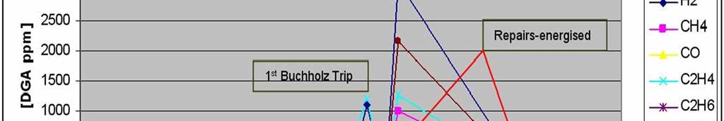
34 1997/05/ /04/ /02/ /01/20 CO Expon. (CO) 1996/12/17 Bay 22 Rectifier Serial No N /12/ /12/ /11/ /11/ /11/ /11/11 CH4 C2H2 1996/10/ /10/ /09/ /09/ /09/ /09/ /08/ /08/22 %H2/TCG C2H6 1996/08/ /07/ /07/ /07/ /04/ /11/ /06/14 T22 Transformer Failure-93.5 MVA The DGA on this transformer showed abnormal gas production of H2 CH4 C2H4 and C2H6 about 20 months after Energisation C2H4 Poly. (C2H4)
35 This transformer was ranked as having the highest risk of failure, based on the DGA-Total Combustible Gas profile The condition was monitored by regular oil samples. On-line DGA was considered Rectifiers TCG Profile July 2001 [TCG] TCG 0 Bay10 Bay11 Bay12 Bay13 Bay14 Bay15 Bay16 Bay21 Bay22 Bay23 Bay24 Bay25 Bay26 Bay27


36 Failure Event At 16:32, on the 18 November 2005, Transformer T22 BANG De-Gassing Unit Failure When T22 transformer failure developed, the entire sequence of events, equipment failures and trips were over in approximately one second.

37 900 MW wiped off the National Grid Potline 1 offline for 75 min Potline 2 offline for 145 min Major impact to Production (output and process stability) Damage to critical Control circuits Loss of N-1 redundancy in Transformer Supply Disaster Averted Consequence An outage > 180 mins often leads to a prolonged shutdown of an Aluminium plant up to a year Zero injuries sustained


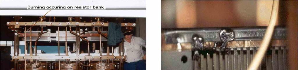
38 Internal Inspection and findings High Voltage winding open circuit and flashed to core Burning in the vicinity of the top core earth strap Overheating of the Core


39 Investigation: Bay 21 Rectifier Doble Engineering: Electrical diagnostic revealed problem. DGA scoring system scores this transformer between 80 and 100 DGA signatures are indicative of a localized thermal fault probably of the bare metal rather than covered conductor SFRA revealed significant problems with the HV winding. Internal Inspection and findings Striking resemblance of core defect between T22 and T21


40 Root Cause and the next step Root cause of gassing was attributed to a poor shielding design or reduced cross sectional area of core Early retirement of all Rectifiers of this design. On Line DGA monitors installed
41 Conclusions The transformer problems at the Hillside smelter fit the Bath Tub Life Cycle Model The application of DGA was 100% successful in identify the faults at early life. DGA oil testing is typically a critical first step in any power transformer analysis. Transformer manufacturers need to balance the cost of equipment with reliability. Experience and understanding of the diagnostic methods is required to make DGA a more exact science and not an art.


42 Whew!!!!!!!! I m out of here! Thank you