Crack Morphology in a Columnar Thermal Barrier Coating System
|
|
|
- Jonas Chase
- 5 years ago
- Views:
Transcription


1 Crack Morphology in a Columnar Thermal Barrier Coating System Anne Dennstedt, Fabrice Gaslain, Marion Bartsch, Vincent Guipont, Vincent Maurel Centre des Matériaux - Mines ParisTech - CNRS UMR PSL Research University Institute of Materials Research German Aerospace Center Cologne (anne.dennstedt@dlr.de) 1
2 Outlook Introduction Damage features in service and laboratory experiments Laser Shock Adhesion Test (LASAT) Characterization of damages introduced by LASAT 3 dimensional imaging by FIB-slice & view Summary and conclusions 2

3 Application of Thermal Barrier Coatings Aero engine GP 7000, Engine Alliance: GE Aircraft Engines and Pratt & Whitney Artwork: Engine Alliance 3


4 Application of Thermal Barrier Coatings Mat metallic: protective alloy layer White: ceramic thermal barrier layer Coated turbine blades for aero engines Aero engine GP 7000, Engine Alliance: GE Aircraft Engines and Pratt & Whitney Artwork: Engine Alliance 4

5 Processing and microstructure of columnar TBC s by EB-PVD Electron gun Specimen ZrO 2 TBC TBC 1 10 µm TGO Ceramic vapor Al 2 O 3 Bond Coat 10 µm 5 µm Vacuum chamber Ceramic ingot NiCoCrAlY Ni-base superalloy TBC: ZrO 2 stabilized with 6-8 wt % Y 2 O 3 TGO: Thermally Grown Oxide, Al 2 O 3 Bond-Coat: Aluminum rich alloy Electron Beam - Physical Vapor Deposition 5


6 Damage features in service and laboratory experiments For characterizing the adhesion of a coating system: - The properties of that specific interface have to be assessed - Laboratory tests should induce delamination at this interface A facility to characterize TBC adhesion has been developed at MINES ParisTech: Turbine blade of aero engine Spallation of ceramic layer during service preferred at TGO, near to the interface between bond coat and ceramic top coat nach? Langstreckenflügen 6

 measurement 3. 45 mirror 4.")


7 Laser Shock Adhesion Test - LASAT MINES ParisTech 3 1. Polarising lens to vary E (J) 2. E(J) measurement mirror 4. Focusing lens and Laser shock Saga Thales Laser: maximum energy 2J pulse duration 7 ns wavelength 532 nm power density 0,1-10GW/cm² SAMPLE No specific geometry No contact Local assessment Debonding threshold 7
 tensile shock wave (by reverberation phenomenon & to the opposite direction) (E) debonding the ceramic coating for high loading stress G. Fabre et al.")
8 LAser Shock Adhesion Test (LASAT) A tool to characterize adhesion Principle of LASAT: (A) focused high power short pulse laser (B) sudden expansion of generated plasma (C) Compressive shock wave, reflected on the opposite free surface (D) tensile shock wave (by reverberation phenomenon & to the opposite direction) (E) debonding the ceramic coating for high loading stress G. Fabre et al., Advanced Materials Research 278 (2011) p
9 Aim of the work Producing a known defect in size and location by LASAT How to characterize the morphology of the crack tip in a brittle multi-layered system? 9

10 LASAT threshold Series of LASAT and IR thermography Find the LASAT threshold using shocks with decreasing laser energy Infra-red thermography: first control for damage at the position treated & estimation of delamination diameter 10


11 Sample preparation & SEM sample embedded in transparent resin to analyze details during grinding and polishing: check for appearance of crack by optical microscope 1 cm SEM: crack by LASAT in the cross section Crack tip investigated by FIB-SEM 11


 Observation with secondary")
12 FIB-SEM experiment Subsequent slicing by focused ion beam and imaging by SEM provides information for 3-D construction of the crack tip region Top view View direction Observation with backscattered electrons (BSE) Observation with secondary electrons (SE) 12


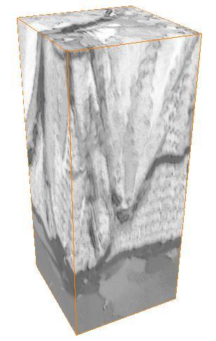
 µm³ Voids = cracks")
13 Microstructure in ceramic coating Volume obtained after alignment and combination of the image slices Cross sections: Gaps between columns indicated Material segmentation for further analyses: Size of volume: (11.0 x x 14.2) µm³ Voids = cracks & gaps Green: segmented gaps between columns 13
14 Segmentation of image stack Using both image stacks 14
15 Segmentation of image stack Using both image stacks Assign bond coat Red = bondcoat 15
16 Using both image stacks Assign bond coat Segmentation of image stack Assign ceramic Red = bondcoat Blue = YSZ ceramic 16


17 Using both image stacks Assign bond coat Segmentation of image stack Assign ceramic Use SE images to assign TGO and voids Red = bondcoat Blue = YSZ ceramic 17


18 Phase distribution along coating thickness Bond coat top coat Segmentation for each horizontal slice Calculated volume fractions of each phase as detected for each slice/image - Presence of multiple phases due to rough interfaces - Characteristic locations: first occurrence of a phase and maximum volume fraction of phases 18

19 Use of sub-volumes to analyze crack path 19


20 Use of sub-volumes to analyze crack path BSE image SE image BSE image SE image BSE image SE image 20


21 Use of sub-volumes to analyze crack path Differentiation between cracks and gaps Crack below and on top of TGO Small crack in ceramic Larger crack in ceramic and some gaps Crack on top of TGO 21
22 Summary and conclusions Damage of TBC system induced by LASAT 3D characterization of microstructure and crack (FIB slice & SEM): Columnar microstructure of the ceramic coating, with connections and gaps between the columns Cracks between bond coat and TGO, inside the TGO as well as between TGO and ceramic but also inside the ceramic columns Cracks + gaps: complex system of voids Systematic analysis of sub-volumes allows crack path analyses (crack positions and orientation) Characterization method can be further utilized for analyzing crack morphologies in TBC systems after service and laboratory tests such as LASAT 22
23 Acknowledgement The Authors thank for the financial support supplied by Mines ParisTech and acknowledge the Zuse-Institute Berlin (ZIB) for helpful discussions and providing access to the image analyses program AVIZO. Part of this work was carried out within the MATMECA consortium and supported by the ANR under contract number ANR-10-EQUIPEX-37. Thank you for your attention! 23


24 Supplementary information Based on the proposed segmentation 3D realistic FEA could be achieved (elastic analysis) Radius = IR measurement: 3 mm Radius = IR µm defect Systematic error by IR measurement ~ 100 µm Stress state after cooling for 2D axisymmetric assumption 3D realistic FEA can be used to further determine the role of real morphology on Heat flux and subsequent thermal conductivity Localization of strain and stress Process zone associated to the crack tip radius R0 = IR measured deflection 30 µm R µm 31 µm R µm 33 µm d/d0 1,12 1,08 1,06 1,04 1,02 Impact of uncertainty of crack tip measurement 1, ,05 1,1 R/R0 Supplementary information 24
25 Supplementary information Related publications by authors: H. Sapardanis, V. Maurel, A. Köster, S. Duvinage, F. Borit, & V. Guipont, Influence of macroscopic shear loading on the growth of an interfacial crack initiated from a ceramic blister processed by laser shock. Surf. Coat. Techn. 291(2016) R. Soulignac, V. Maurel, L. Rémy & A. Köster, Cohesive zone modelling of thermal barrier coatings interfacial properties based on threedimensional observations and mechanical testing. Surf. Coat. Techn. 237 (2013) M. Bartsch, B. Baufeld, S. Dalkilic, L. Chernova, M. Heinzelmann: Fatigue cracks in a thermal barrier coating system on a super alloy in multiaxial thermomechanical testing, Int. J. fatigue 30 (2008) doi: /j.ijfatigue M. Hernandez, A. Karlsson, M. Bartsch: On TGO creep and the initiation of a class of fatigue cracks in thermal barrier coatings, Surf. Coat. Techn. 203 (2009) DOI: /j.surfcoat A.C. Manero II, S. Sofronsky, K. Knipe, C. Meid, J. Wischek, J. Okasinski, J. Almer, A.M. Karlsson, S. Raghavan, M. Bartsch: Monitoring Local Strain in a Thermal Barrier Coating System under Thermal Mechanical Gas Turbine Operating Condition, JOM 67 (7) (2015) Contact addresses of authors: Anne Dennstedt, DLR & Mines ParisTech, anne.dennstedt@dlr.de Vincent Maurel, Mines ParisTech, vincent.maurel@mines-paristech.fr Vincent Guipont, Mines ParisTech, vincent.guipont@mines-paristech.fr Fabrice Gaslain, Mines ParisTech, fabrice.gaslain@mines-paristech.fr Marion Bartsch, German Aerospace Center, marion.bartsch@dlr.de 25