CHAPTER. The Structure of Crystalline Solids
|
|
|
- Alberta Clarke
- 5 years ago
- Views:
Transcription
1 CHAPTER 4 The Structure of Crystalline Solids 1
2 Chapter 4: The Structure of Crystalline Solids ISSUES TO ADDRESS... What are common crystal structures for metals and ceramics? What features of a metal s/ceramic s atomic structure determine its density? How do the crystal structures of ceramic materials differ from those for metals? 2

 Schematic diagram illustrating how the")
 is indicated by the diffraction spot")
 Photograph of a single crystal of Mg")
3 Structure of Crystalline Solids (a) X-ray diffraction photograph for a single crystal of magnesium (Mg). (b) Schematic diagram illustrating how the spots in (a) are produced. (c) is indicated by the diffraction spot pattern that was generated. (d) Photograph of a single crystal of Mg (0001) plane. (e) Photograph of a mag wheel -a light-weight Mg automobile wheel 3
4 4.1 Metallic Crystal Structures Tend to be densely packed. Reasons for dense packing: - Typically, only one element is present, so all atomic radii are the same. - Metallic bonding is not directional. - Nearest neighbor distances tend to be small in order to lower bond energy. - Electron cloud shields cores from each other. Metals have the simplest crystal structures. We will examine three such structures... 4
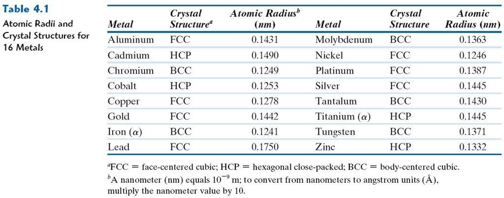
5 Table_04_01
6 4.2-4 Metallic Crystal Structures How can we stack metal atoms to minimize empty space? 2-dimensions vs. Now stack these 2-D layers to make 3-D structures 6
 Close-packed directions are cube edges.")
7 Simple Cubic Structure (SC) Rare due to low packing density (only Po has this structure) Close-packed directions are cube edges. Coordination # = 6 (# nearest neighbors) 7

8 Atomic Packing Factor (APF) APF = Volume of atoms in unit cell* Volume of unit cell *assume hard spheres APF for a simple cubic structure = 0.52 a close-packed directions contains 8 x 1/8 = 1 atom/unit cell R = 0.5a atoms unit cell APF = 1 volume 4 π (0.5a) 3 atom 3 a 3 volume unit cell 8


9 Body Centered Cubic Structure (BCC) Atoms touch each other along cube diagonals. --Note: All atoms are identical; the center atom is shaded differently only for ease of viewing. ex: Cr, W, Fe ( ), Tantalum, Molybdenum Coordination # = 8 2 atoms/unit cell: 1 center + 8 corners x 1/8 9

10 VMSE Screenshot BCC Unit Cell 10
11 Atomic Packing Factor: BCC APF for a body-centered cubic structure = a a 2 a R a Close-packed directions: length = 4R = 3 a atoms unit cell APF = π ( 3 a/4 ) 3 a 3 volume atom volume unit cell 11


12 Face Centered Cubic Structure (FCC) Atoms touch each other along face diagonals. --Note: All atoms are identical; the face-centered atoms are shaded differently only for ease of viewing. ex: Al, Cu, Au, Pb, Ni, Pt, Ag Coordination # = 12 4 atoms/unit cell: 6 face x 1/2 + 8 corners x 1/8 12
13 Atomic Packing Factor: FCC APF for a face-centered cubic structure = 0.74 maximum achievable APF 2 a a Close-packed directions: length = 4R = Unit cell contains: 6 x 1/2 + 8 x 1/8 = 4 atoms/unit cell 2 a atoms unit cell APF = π ( 2 a/4 ) 3 a 3 volume atom volume unit cell 13
14 FCC Stacking Sequence ABCABC... Stacking Sequence 2D Projection A sites B sites C sites A B B C B C B B C B B FCC Unit Cell A B C 14
15 Hexagonal Close-Packed Structure (HCP) ABAB... Stacking Sequence 3D Projection 2D Projection c A sites B sites Top layer Middle layer a A sites Bottom layer Coordination # = 12 APF = atoms/unit cell ex: Cd, Mg, Ti, Zn c/a =

16 VMSE Screenshot Stacking Sequence and Unit Cell for HCP 16
17 4.5 Theoretical Density, r Density = r = r = Mass of Atoms in Unit Cell Total Volume of Unit Cell n A V C N A where n = number of atoms/unit cell A = atomic weight V C = Volume of unit cell = a 3 for cubic N A = Avogadro s number = x atoms/mol 17
18 Theoretical Density, ρ Ex: Cr (BCC) A = g/mol R = nm n = 2 atoms/unit cell R a a = 4R/ 3 = nm atoms unit cell r = volume a x g mol ρ theoretical ρ actual atoms = 7.18 g/cm 3 = 7.19 g/cm 3 unit cell mol 18


19 Atomic Bonding in Ceramics Bonding: -- Can be ionic and/or covalent in character. -- % ionic character increases with difference in electronegativity of atoms. Degree of ionic character may be large or small: CaF 2 : large SiC: small 19
20 Table_04_02
21 4.6 Ionic Arrangement Geometries - Ceramic Crystal Structures Oxide structures oxygen anions larger than metal cations close packed oxygen in a lattice (usually FCC) cations fit into interstitial sites among oxygen ions 21
22 Factors that Determine Crystal Structure 1. Relative sizes of ions Formation of stable structures: --maximize the # of oppositely charged ion neighbors unstable 2. Maintenance of Charge Neutrality : --Net charge in ceramic should be zero. --Reflected in chemical formula: A m X p stable CaF 2 : stable Ca 2+ cation + F - anions F - m, p values to achieve charge neutrality 22
 0.155-0.225 0.225-0.414 3 4 triangular tetrahedral NaCl (sodium chloride) 0.414-0.732 0.732-1.")
23 Coordination Number and Ionic Radii r cation Coordination Number increases with r anion To form a stable structure, how many anions can surround around a cation? r cation r anion < Coord. Number 2 linear ZnS (zinc blende) triangular tetrahedral NaCl (sodium chloride) octahedral cubic CsCl (cesium chloride) 23
24 Computation of Minimum Cation-Anion Radius Ratio Determine minimum r cation /r anion for an octahedral site (C.N. = 6) a = 2r anion 2r anion + 2r cation = 2 2r anion r anion + r cation = 2r anion r cation = ( 2-1)r anion rcation = 2-1= r anion
25 r cation r anion =
26 Bond Hybridization Bond Hybridization is possible when there is significant covalent bonding hybrid electron orbitals form For example for SiC X Si = 1.8 and X C = 2.5 ~ 89% covalent bonding Both Si and C prefer sp 3 hybridization Therefore, for SiC, Si atoms occupy tetrahedral sites 26
27 Example Problem: Predicting the Crystal Structure of FeO On the basis of ionic radii, what crystal structure would you predict for FeO? Cation Al 3+ Fe 2 + Fe 3+ Ca 2+ Anion O 2- Cl - F - Ionic radius (nm) Answer: r r cation anion = = based on this ratio, -- coord # = 6 because < < crystal structure is NaCl 27
28 AX Crystal Structures AX Type Crystal Structures include NaCl, CsCl, and zinc blende Cesium Chloride structure: Since < < 1.0, cubic sites preferred So each Cs + has 8 neighbor Cl - 28
29 Rock Salt Structure Same concepts can be applied to ionic solids in general. Example: NaCl (rock salt) structure r Na = nm r Cl = nm r Na /r Cl = cations (Na + ) prefer octahedral sites 29
30 MgO and FeO MgO and FeO also have the NaCl structure O 2- Mg 2+ r O = nm r Mg = nm r Mg /r O = cations prefer octahedral sites So each Mg 2+ (or Fe 2+ ) has 6 neighbor oxygen atoms 30

31 Zinc blende ZnS Fig_04_07

32 AX 2 Crystal Structures Fluorite structure Calcium Fluorite (CaF 2 ) Cations in cubic sites UO 2, ThO 2, ZrO 2, CeO 2 Antifluorite structure positions of cations and anions reversed 32

33 ABX 3 Crystal Structures Perovskite structure Ex: complex oxide BaTiO 3 33

34 VMSE Screenshot Zinc Blende Unit Cell 34
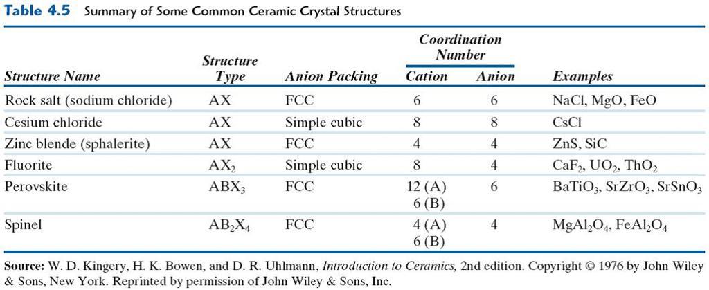
35 Table_04_05
36 4.10 Density Computations for Ceramics Number of formula units/unit cell Volume of unit cell Avogadro s number = sum of atomic weights of all cations in formula unit = sum of atomic weights of all anions in formula unit 36
37 Densities of Material Classes In general ρ metals > ρ ceramics > ρ polymers Why? Metals have... close-packing (metallic bonding) often large atomic masses Ceramics have... less dense packing often lighter elements ρ (g/cm 3 ) Polymers have... low packing density (often amorphous) lighter elements (C,H,O) Composites have... intermediate values Metals/ Alloys Platinum Gold, W Tantalum Silver, Mo Cu,Ni Steels Tin, Zinc Titanium Aluminum Magnesium Graphite/ Ceramics/ Semicond Polymers Data from Table B.1, Callister & Rethwisch, 9e. Composites/ fibers B ased on data in Table B1, Callister *GFRE, CFRE, & AFRE are Glass, Carbon, & Aramid Fiber-Reinforced Epoxy composites (values based on 60% volume fraction of aligned fibers in an epoxy matrix). Zirconia Al oxide Diamond Si nitride Glass - soda Concrete Silicon G raphite PTFE Silicone PVC PET PC H DPE, PS PP, LDPE Glass fibers GFRE* Carbon fibers CFRE * A ramid fibers AFRE * Wood 37
 polymorphic forms")
 for this material")
38 4.11 Silicate Ceramics Most common elements on earth are Si & O Si 4+ O 2- crystobalite SiO 2 (silica) polymorphic forms are quartz, crystobalite, & tridymite The strong Si-O bonds lead to a high melting temperature (1710ºC) for this material 38
39 Silicates Bonding of adjacent SiO 4 4- accomplished by the sharing of common corners, edges, or faces Mg 2 SiO 4 Ca 2 MgSi 2 O 7 Presence of cations such as Ca 2+, Mg 2+, & Al maintain charge neutrality, and 2. ionically bond SiO 4 4- to one another 39
40 Basic Unit: 4- Si0 4 tetrahedron Si 4+ Glass Structure O 2 - Glass is noncrystalline (amorphous) Fused silica is SiO 2 to which no impurities have been added Other common glasses contain impurity ions such as Na +, Ca 2+, Al 3+, and B 3+ Quartz is crystalline SiO2: Na + Si 4+ O 2 - (soda glass) 40
 SiO 4 tetrahedra connected together to form 2-D plane A net negative charge is associated with each (Si 2 O 5")
41 Layered Silicates Layered silicates (e.g., clays, mica, talc) SiO 4 tetrahedra connected together to form 2-D plane A net negative charge is associated with each (Si 2 O 5 ) 2- unit Negative charge balanced by adjacent plane rich in positively charged cations 41
42 Layered Silicates (cont) Kaolinite clay alternates (Si 2 O 5 ) 2- layer with Al 2 (OH) 2+ 4 layer Note: Adjacent sheets of this type are loosely bound to one another by van der Waal s forces. 42
43 4.12 Polymorphic Forms of Carbon Diamond tetrahedral bonding of carbon hardest material known very high thermal conductivity large single crystals gem stones small crystals used to grind/cut other materials diamond thin films hard surface coatings used for cutting tools, medical devices, etc. 43
44 Polymorphic Forms of Carbon (cont) Graphite layered structure parallel hexagonal arrays of carbon atoms weak van der Waal s forces between layers planes slide easily over one another -- good lubricant 44
45 4.13 Crystallinity in Polymers Ordered atomic arrangements involving molecular chains Crystal structures in terms of unit cells Example shown polyethylene unit cell 45
46 4.14 Polymorphism Two or more distinct crystal structures for the same material (allotropy/polymorphism) titanium α, β -Ti carbon diamond, graphite iron system liquid 1538 C BCC δ -Fe 1394 C FCC γ -Fe BCC 912 C α -Fe 46
47 Polymorphism or Allotropy Metals exist in more than one crystalline form. This is called polymorphism or allotropy. Temperature and pressure leads to change in crystalline forms. Example:- Iron exists in both BCC and FCC form depending on the temperature. Liquid Iron C C C C α Iron BCC γ Iron FCC δ Iron BCC 47
48 4.16 Linear Density Linear Density of Atoms LD = Number of atoms Unit length of direction vector [110] ex: linear density of Al in [110] direction a = nm a # atoms length LD = 2 = 2 a 3.5 nm
 a = 4 3 3 R atoms 2D repeat unit 1 Planar Density = a 2 area 2D repeat unit = 4 3 1 3 R Radius of iron R = 0.")
49 Planar Density of (100) Iron Solution: At T < 912 C iron has the BCC structure. 2D repeat unit (100) a = R atoms 2D repeat unit 1 Planar Density = a 2 area 2D repeat unit = R Radius of iron R = nm 2 = atoms 12.1 nm 2 = 1.2 x atoms m 2 49
50 Planar Density of (111) Iron Solution (cont): (111) plane 1 atom in plane/ unit surface cell 2 a atoms in plane atoms above plane atoms below plane atoms 2D repeat unit Planar Density = area 2D repeat unit R = atoms 7.0 = nm 2 h = area = 2 ah = 3 a = 3 R = x a R atoms m
 Plane for")
51 VMSE Screenshot Atomic Packing (111) Plane for BCC 51

52 4.17 Close-packed Crystal Structures Fig_04_23
")
53 Hexagonal close-packed (HCP) Fig_04_24
")
54 Face-centered cubic (FCC) Fig_04_25
 positions")
55 Tetrahedral (CN=4) and Octahedral (CN=6) positions Fig_04_26

56 NaCl structure Na cations occupy the interstitial octahedral sites Fig_04_27
57 4.18 X-Ray Diffraction Diffraction gratings must have spacings comparable to the wavelength of diffracted radiation. Can t resolve spacings λ Spacing is the distance between parallel planes of atoms. 57
58 X-Rays to Determine Crystal Structure Incoming X-rays diffract from crystal planes. extra distance travelled by wave 2 θ θ λ d reflections must be in phase for a detectable signal spacing between planes Measurement of critical angle, θ c, allows computation of planar spacing, d. X-ray intensity (from detector) d = n λ 2 sin θ c θ θ c 58
59 Intensity (relative) X-Ray Diffraction Pattern c z c z c z a x b y (110) a x b y a x (211) b y (200) Diffraction angle 2θ Diffraction pattern for polycrystalline α-iron (BCC) 59
60 Summary Common metallic crystal structures are FCC, BCC, and HCP. Coordination number and atomic packing factor are the same for both FCC and HCP crystal structures. We can predict the density of a material, provided we know the atomic weight, atomic radius, and crystal geometry (e.g., FCC, BCC, HCP). Interatomic bonding in ceramics is ionic and/or covalent. Ceramic crystal structures are based on: -- maintaining charge neutrality -- cation-anion radii ratios. Some materials can have more than one crystal structure. This is referred to as polymorphism (or allotropy). X-ray diffraction is used for crystal structure and interplanar spacing determinations. 60