Additive Manufacturing For Industrial Applications DNV-GL Technology Week
|
|
|
- Valerie Kelly
- 5 years ago
- Views:
Transcription


1 Additive Manufacturing For Industrial Applications DNV-GL Technology Week


2 2 Who We Are: Carpenter Technology s Evolution Transitioned from a steel to specialty alloy focused company supported by 128+ years of metallurgical expertise Today, we are a high performance materials and advanced process solutions provider for critical end-use applications Metal technology capabilities for a wide range of next-generation products and manufacturing techniques Evolving to next generation end-to-end additive manufacturing solutions provider


3 3 History & Milestones: Powder and Additive Manufacturing 40+ years in advanced powder technology 1980 s-1990 s Gas Atomized Powder R&D CPP Bridgeville Acquired 1997 CPP Sweden Acquired 2000 Ultrafine powder Acquired 2008 Built superalloy gas atomizer Athens, AL Titanium powder Acquired 2017 Additive Manufacturing Technology Center commissioned 2017 Announced Emerging Technology Center Athens, AL 2019 Metal component additive manufacturing Founded 2005 Over 3000 build cycles Multiple flight qualifications Acquired 2018 History of innovation in powder and AM technology

4 4 Overview Introduction to AM How Carpenter participates in AM What metals AM can do What metals AM cannot do Nickel 718 Material Design Case Study What fundamental problem are we trying to solve?
")

 CalRAM Each approach suited to own")
 ~10 commercially available")
5 5 Technologies Overview Laser PBF EBM Binder jetting & DED 80% of machines 10% of machines ~10% of machines Fine powder (~15-63µm) ~15 commercially available materials (Ti64, CoCrMo, 316L, 17-4PH, C300, 718, 625, etc Reading AM Tech Center & CalRAM Coarser powder (~45-105µm) ~3 commercially available materials (Ti64, 718, CoCrMo) Currently 1 OEM (GE) CalRAM Each approach suited to own applications and markets MIM cut to fine powder for binderjetting Coarse powder for DED (~45-200µm) ~10 commercially available materials Reading AMTC

6 6 What AM Can Do Elimination of Design Constraints Flexibility to manufacture parts that would not be possible or economically feasible to produce using traditional manufacturing Reduced Cost of Complexity AM technology enables users to produce complex parts at little or no incremental cost versus simple parts Reduced Time to Market AM enables digital designs to be printed, tested, evaluated, and modified quickly Repair and replacement parts One Seamless Part AM allows the ability to produce one seamless part, which historically would have required the assembly and welding of multiple parts together Mass Customization Because 3D printers do not require tooling or significant setup costs, users are able to produce customized parts in a costeffective manner Cost Effective Production The upfront tooling and setup costs required in traditional manufacturing are not required when using AM technologies


 Landing gear forgings")
 Engine shafts (Ni) Drill")
 Bearings (Ni) High speed")
")


7 AM does Not Replace Traditional Manufacturing It Complements It Unlikely / distant Substitution or enhancement by AM Likely / already Ducting & tubing (Ni) Medical implants (CoCr, Ti) Landing gear forgings (maraging steel) Forged rings/discs (Ni alloys) Engine shafts (Ni) Drill collars (non-magnetic) Flap tracks (maraging) Bearings (Ni) High speed tooling Tooling: dies & molds LWD Tools Fasteners (Ni, steel, Ti) Electrical laminations Unlikely to be impacted by AM, other than indirectly (e.g., through tooling) 1 1) Why? Large, simple shapes, critical parts requiring significant forging/upsetting, high volume components such as fasteners, and sheet form all unsuited to AM However, it will have a material impact on future designs and manufacturability 7


 powders")


8 AM Powder and Wire Production Titanium and Nickel wire used in direct deposition Alabama State of the art superalloy facility West Virginia High purity Ti alloy powders Rhode Island Ultrafine (MIM) powders Sweden Stainless & Tool steels Pennsylvania 2x VIM and 1x air melt atomizers High temperature superalloys Titanium Gamma TiAl Binder Jet alloys Tool steel Stainless steel Specialty grades Production capacity to scale with customers growth 8
 Bruceton Mills, West")
9 9 Acquired Puris LLC (Titanium Powder) in March 2017 Electrode Induction Melt Gas Atomization (EIGA) Bruceton Mills, West Virginia


10 10 Use of Different Particle Sizes Fine wire Deposition & EB-PBF Mid Cut µm L-PBF Fine µm µm Binder Jet / MIM Ultrafine 0-22 µm ISO/ASTM 52900: L-PBF = Laser Powder Bed Fusion; EB-PBF = Electron Beam Powder Bed Fusion; MIM = Metal Injection Molding Each type of AM requires optimized raw material size and shape

11 Advancing Breadth of AM Materials Across All Platforms Proprietary process guidance for: Type Alloy EBeam-PBF Laser-PBF Binder Jet *Additional alloys being prioritized through strategic partnerships Titanium Ti-6-4 Ti Gamma TiAl C.P. Ti Aluminum AlSi10Mg AM Nickel Cobalt Steels 625 HX H In development CoCrMo In development In development In development Micro-Melt 6 In development In development CCW+ In development In development M300/C300 (1.2709) Custom Cr-4Ni 316L In development 420 In development In development H13 Tool Steel In development In development Copper C18200 (CuCr)

12 12 Reading AM Technology Center Alloy & Process Support Alloy development & commercialization Fundamental materialprocess interactions Process windows for novel alloys Heat Treat & HIP cycle innovation Alloy Development Global, world-class R&D capabilities Broad, diverse network including national labs, industrial research labs, & universities Focus on partnering with customers to develop alloys for critical applications Multiple R&D 100 Awards Additive Equipment SLM 125 (L-PBF) SLM 280 HL Dual Lasers (L-PBF) 3D Systems ProX320 (L-PBF) Trumpf TruPrint 1000 (L-PBF) ExOne MFlex (Binder Jet) ExOne Innovent (Binder Jet) Optomec LENS MR7 (Direct Energy Deposition) Expertise to support end-to-end development needs Other Capabilities R&D vacuum melt atomization Powder characterization Powder handling protocols Metallurgical testing Microstructure analysis Vacuum sintering Hot Isostatic Press (HIP)


 (1) ARCAM S12 - Modified (epbf) (1) SLM 280")
 Respected")
13 13 CalRAM Inc. -- Full Solution Metal AM Production Design & Engineering Additive Production In house post processing Over 3000 build cycles completed since 2005 Flight qualified with multiple OEMs B-Basis allowables developed for Ti-6-4 Metrology inspection Capabilities Accreditations 25,000 sqft manufacturing space (3) ARCAM A2X (epbf) (1) ARCAM S12 - Modified (epbf) (1) SLM 280 HL - Dual Lasers (LPBF) Metallurgical expertise and focus Design change management protocol (IP) Respected industry leader for AM part production in AS&D and Energy applications


14 14 Emerging Technology Center for Low Rate Initial Production The early stage research solutions can be scaled up for production through our ETC

15 15 Each New Material & Application Faces Challenges Metallurgy Metrology Application Business Case Control of defects e.g. voids Susceptibility to microcracking Alloys not designed for AM Anisotropic properties Unknown acceptable ranges of process variation Dimensional accuracy Support & thermal management Feature-based melt parameters Streamlined post-processing Yield & productivity Tradeoffs vs. casting Product lifecycle costs Insource vs. outsource? Qualification time & cost CapEx to scale Carpenter approaching challenges from the materials perspective


16 16 Print Parameters: Need for Controlled Process Poor control of process & powder Good control of process & powder Process defect Powder defects What changed? Powder refinement for example, minimized gas entrapment Parameter optimization more consistent welding Carefully manage powder, part orientation, and machine processing conditions

17 Leveraging Deep Knowledge and Capital Assets for Tailored Alloy Solutions 17
, 4hr T5:Sol An/Age at 1800 F (980 C) for 1 hr, Cool to 1330 F (720 C) hold 8hr, cool to 1150 F (620 C) hold 8hr cool to RT T6: Met")
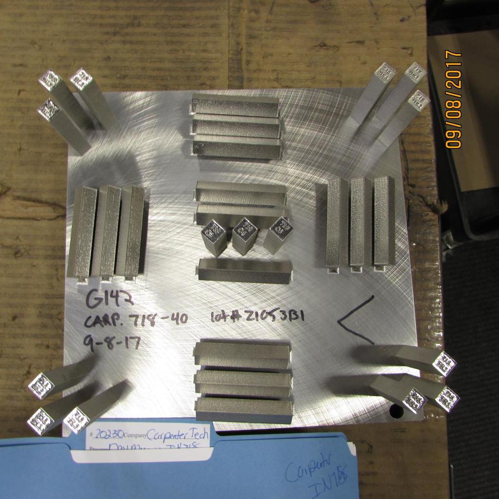
18 18 Process Flow Chart 718 Specimens T1: DMLM Processed specimen T6: Met Porosity T2: EDM from Plate T4:HIP at 2175 F, (1191 C), 15 ksi (100 Mpa), 4hr T5:Sol An/Age at 1800 F (980 C) for 1 hr, Cool to 1330 F (720 C) hold 8hr, cool to 1150 F (620 C) hold 8hr cool to RT T6: Met Specimens


19 19 As-built vs heat Treated Microstructure (as built) 718 microstructures Transverse Longitudinal (Sol Anl/ Age HT) 718 microstructures The delta phase is an Ni 3 Nb intermetallic
 718 microstructures")


20 20 Effect of HIP- Grain Size (Sol Anl/Age HT) 718 microstructures Transverse Longitudinal The delta phase is an Ni 3 Nb intermetallic Grain Size: nonequiaxed ~4. (HIP/ Sol Anl/Age HT) 718 microstructures Grain Size: wide range, 2-7 avg. 5.
21 21 Effect of HIP Porosity (Sol An/ Age HT) 718 microstructures Vertical Horizontal (HIP/ Sol An/ Age HT) 718 microstructures

22 Final Parameter Selection for Alloy 718 Mean porosity 0.02 % Density 99.98% 40 μm Layers, SE 67.5 J/mm 3 22

23 23 CVN Specimens Tensile Specimens
24 24 Charpy Impact Test Results Horz As Built Impact Energy (ft-lbs) Vert Impact Energy (ft-lbs) (Sol An/Age HT) Horz Impact Energy (ft-lbs) Vert Impact Energy (ft-lbs) (HIP/Sol An/Age HT) Horz Impact Energy (ft-lbs) Vert Impact Energy (ft-lbs) HC-1 75 C-4 77 HR-1 80 FR-1 75 HL-1 77 FL-1 75 HF-1 77 BL-1 73 HB-1 76 BR-1 73 Mean 77 Mean 74.6 sd 1.67 sd 1.5 B BL F3 13 BR L FL R FR C C Mean Mean sd 0.76 sd 0.99 B BL C BR2 23 F FL L FR R2 18 C Mean Mean sd 0.49 sd 1.21
25 Tensile Testing Results LPBF Properties As Built V AS Built H Sol HT V Sol HT H Hip/Sol HT V Hip/Sol HT H 0 YS (ksi) UTS (ksi) EL (%) RA (%) EOS As built 718: H; ys 113 ksi, uts-154 ksi, EL% - 27, V ys-92 ksi, uts-142 ksi, EL%-31 F a as built: H; ys 92.1 ksi, uts-142 ksi, EL% - 27, V ys-87 ksi, uts-133 ksi, EL%-27 25


26 26 Leveraging Deep Knowledge and Capital Assets for Tailored Alloy Solutions Translating powder chemistry and printing parameters into optimal microstructures and properties.


27 What Fundamental Industrial Problems Are We Solving? Examples of AM Projects: Inflow control devices Flow manifolds Valve bodies & inserts Erosion control Filters Turbochargers/turbines Heat shrouds Heat exchangers Fuel injectors Fuel nozzles Instrumentation housings Tooling Jigs & fixtures 27
28 Questions? 28