A Comparison of Static Axial Capacity Between Drilled and Driven Piles. Outline
|
|
|
- Kevin Tucker
- 5 years ago
- Views:
Transcription
1 A Comparison of Static Axial Capacity Between Drilled and Driven Piles Dr. Steven Dapp, P.E. Dan Brown and Associates, LLC Outline Factors Affecting Driven Pile Performance Factors Affecting Drilled Pile Performance (emphasis on CFA piles) Comparison of Unit Capacities Case History / Comparative Tests Advantages/Disadvantages 1
2 Factors Affecting Driven Pile Performance Effect of Pile Installation on Soil Effect of Time Residual Stresses Construction Control Effect of Pile Driving on Soil Pile displaces and remolds soil Pile installation alters state of stress in the ground 2
3 Effect of Pile Driving on Soil Pile installation alters state of stress in the ground Increase in horizontal stress related to displacement Effect of Pile Driving on Soil Group effects tend to amplify the effects of displacement on stresses and soil densification! 3


4 Effect of Pile Driving on Soil Vesic, A.S., Design of Pile Foundations NCHRP Synthesis of Highway Practice No. 42, TRB, 1977 Effect of Pile Driving on Sandy Soil Pile displaces and remolds soil Sands often densified Ex: Roosevelt Bridge 5X increase in dmt 4
5 Effect of Pile Driving on Clay Soil Pile displaces and remolds soil Remolding/reconsolidation of clay soils McClelland, B. Design of Deep Penetration Piles for Ocean Structures, Journal of the Geotechnical Eng g Div., ASCE, Vol. 100, No. GT7, July, 1974, Effect of Time on Driven Piles Time dependent setup due to: Dissipation of transient pore pressures Relaxation/creep in soil around pile 5

6 Effect of Time on Pore Pressures (Clay Soils) O Neill, M.W Group Action in Offshore Piles Proc., Geotechnical Practice in Offshore Engineering, ASCE, Austin, TX, Effect of Time on Axial Capacity (Clay Soils) Vesic,
7 Effect of Time in Sands Axelsson, G., A Conceptual Model of Pile Set-Up for Driven Piles in Non-Cohesive Soil, GSP 116, ASCE, Effect of Time in Sands Axelsson, G., A Conceptual Model of Pile Set-Up for Driven Piles in Non-Cohesive Soil, GSP 116, ASCE,
8 Residual Stresses in Driven Piles Acts to preload the tip resistance Difficult to measure correctly, but the effect is always there! O Neill, M.W., Hawkins, R.A., and Audibert, J.M.E., Installation of Pile Group in Overconsolidated Clay, Journal of the Geotechnical Eng g Div., ASCE, Vol. 108 No. GT11, Construction Control - Driven Piles Measurement of driving resistance provides some indication of axial capacity Wave Equation Analysis Dynamic Measurements End of Drive measurements usually conservative due to setup Reliability related to hammer performance 8


9 Factors Affecting Drilled Pile Performance Sidewall roughness and adhesion Effect of installation on in-situ stresses Mobilization of tip resistance Construction control Drilled Shafts Tip Grouted w/ Flat-Jack Device Tip Grouted w/ Sleeve-Port Device Not Grouted 9


10 Drilled Shafts Conventional CFA Piles 10


11 Drilled Displacement Piles DeWaal Berkel Omega Fundex Berkel IDD Sidewall Roughness Drilled Piles Bonding of grout/concrete can be terrific in cemented material, e.g. limerock (Miami), cemented sands Remolding in the near field in cohesive materials, ex. = Houston clays where CFA essentially = drilled shaft 11

12 Effect of Drilled Pile Installation on in-situ stresses Lateral stress is reduced by Drilled Shaft installation Lateral stress is typically reduced by conventional CFA Pile installation * Rate of auger penetration is critical in uncemented materials; this needs to be controlled! Effect of Over Excavation in Cohesionless Soil a) auger w/ rapid penetration b) auger w/ slow penetration, insufficient base feed to keep flights full, auger feeds from side Fleming, W.G.K The understanding of continuous flight auger piling, its monitoring and control Proc. Instn Civ. Engrs Geotech. Engng, 113, July,
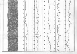
13 Suggested Guidelines for Penetration Rates Clay: 2 to 3 Rev s per auger pitch Sand: 1.5 to 2 Rev s per auger pitch CPT from nearby CFA pile in sandy soil Van Weel, A.F Cast-insitu piles Installation methods, soil disturbance and resulting pile behaviour Proc., 1 st Int l Geotech Seminar on Deep Foundations on Bored and Auger Piles, (Ghent, Belgium) Van Impe, ed, Balkema, Rotterdam,
14 Measurements of in-situ Stress During CFA Pile Installation In Clay Soils O Neill, M. W., Ata, A., Vipulanandan, C., and Yin, S., (2002). Axial Performance of ACIP Piles in Texas Coastal Soils, Geotechnical Special Publication No. 116, Ed. by M. W. O Neill and F. C. Townsend, American Society of Civil Engineers, February, Vol. 1 Measurements of in-situ Stress During a CFA Pile Installation Van Impe, W.F. and Peiffer, H., Influence of screw pile Installation on the stress state in the soil Design of Axially Loaded Piles European Practice, De Cock & Legrand (eds) Balkema, Rotterdam,
15 Mobilization of Tip Resistance Tip resistance MAY require significant displacement to mobilize; very dependent upon soil/rock type and construction technique For ACIP and Drilled Displacement Pile: Grout Pressure may help to mitigate some disturbance. For Drilled Shafts: Tip Grouting may allow for tip mobilization within reasonable displacements, as well as proof test some resistance. Construction Control (Historically a Lack Of ) There is a compelling need for monitoring during installation & withdrawal of augers: Rate of penetration relative to torque & crowd Grouting pressures Grouting volume 15


16 16


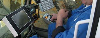
17 Automated Monitoring Systems PIR System Photograph and figures courtesy of Pile Dynamics Inc Construction Control Establish Construction Parameters of Test Piles Load Test Initial Test Piles Hold Contractor to Established Construction Parameters Load Test Some Production Piles Selected by ENGINEER While this greatly helps to ensure a well constructed pile, always remember there is No DIRECT feedback on capacity during installation as with a Driven Pile 17
18 Granular soils: f s = βσ v Closed end pipe (14 ) Precast concrete (12 ) Drilled shafts, Reese & O Neill (FHWA) CFA piles, Zelada and Stevenson, 2000 (GSP 100) CFA piles, Colman and Arcemont 2002 (GSP 116) Drilled Displacement Piles, NeSmith 2002 (GSP 116) US - FHWA Practice Side Shear Method Nordlund, φ = 37 o Nordlund, φ = 34 o Nordlund, φ = 37 o Nordlund, φ = 34 o β= (z,ft) β 1.2 β= z β 0.96 β= z M (Silty) β= z M (Sandy) 0.2 β N+Ws f s 2.2 tsf β Not Used, See Chart Unit Tip resistance 4N spt, tsf 4N spt, tsf 0.6N spt 45 tsf q b = 1.7 N spt 75 tsf No Recommendation 1.9 N+Wt q p 89 tsf Notes: tip for drilled shafts mobilized at 5% x diameter, cfa mobilized at 10%. CFA Piles, Zelada and Stevenson (2000) CFA Piles, Coleman and Arcement (2002) 18
19 Drilled Displacement Piles, NeSmith (2002) CFA Piles, Zelada and Stevenson (2000) 19
20 Drilled Displacement Piles, NeSmith (2002) US - FHWA Practice Clay soils: driven piles Drilled Shafts CFA Piles Method Tomlinson (1987) Reese & O Neill (1999) Colman and Arcemont (2002) Side Shear: α (f s = αc u ) C u < 50 kpa α 1 C u < 150 kpa α = 0.55 Interp. Interp. α = Cu α 2.5 C u > 180 kpa α 0.28 C u > 250 kpa α = 0.45 End Bearing: q tip 9 C u (for all Piles in Clay) 20


21 Case History IFCO Building, Holland Building on 55 piles of 6 different types 7m of soft clay & peat underlain by firm sand Load cell atop each pile, 35 piles subjected to static tests Ref: Van Impe, W.F., Van Impe, P.O., and Verstaeten, K., Experiences with CFA pile type under an existing building Proc., BAPIII,
22 Comparative Tests, Belgium Kallo, Belgium (sand) Ghent, Belgium (sand/clay) B = 600mm S/B Ratio of capacity, bored concrete / driven steel f s q b B = 320 to 450mm S/B 2 10 Ratio of capacity, cfa pile / driven conc. Q total 0.61 to to 0.74 DeBeer., Different behaviour of bored and driven piles, BAPI, Ghent, 1988 CFA Piles Advantages Good side shear bond in cemented materials Low cost Low noise/vibration Easy construction in cohesive soils Drilled Shafts: Rock Sockets Limitations/Problems Inadequate QC/QA (U.S. current practice) Potential for lost ground/subsidence in cohesionless soils No direct field control of axial capacity Concerns for structural integrity, rebar placement GROUP EFFECTS? 22


23 Driven Piles Advantages Displacement pile improves soil Installation process provides feedback on capacity Good control over structural integrity Potential high end bearing on rock or strong layer Group efficiency almost always >100% Limitations/Problems Potential for noise/vibration concerns Handling of long piles Inability to penetrate hard shallow layer w/o driving aids Measured capacity at or shortly after end of driving underestimates capacity Thanks for Listening! 23