Combined effect of molten fluoride salt and irradiation on Ni-based alloys
|
|
|
- Amberly Jefferson
- 5 years ago
- Views:
Transcription
1 Combined effect of molten fluoride salt and irradiation on Ni-based alloys A.S.Bakai, Kharkiv Institute of Physics &Technology, Ukraine

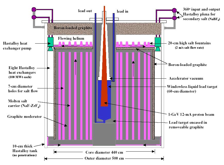
2 Molten Salt Reactor
3
4 Background MSR s and accelerator-driven transmutation technology now under world-wide investigation. Various approaches being studied involve molten salt blanket or coolant. Corrosion and structural integrity of structural components under irradiation are issues requiring study. In the current project electron irradiation at 10 MeV was chosen to simulate neutron irradiation, since the focus of this experiment is on corrosion, a near-surface phenomenon. While neutrons affect bulk properties, corrosion is more impacted by near-surface properties and defects, and by softer parts of the spectra, electrons and gamma radiation. Material development is also a strong part of this project, with a strong focus on investigation of dopants (Nb, Y) impact on the corrosion. Impact of irradiation and molten salt on C-C composite was investigated, too.
5 Methodology Electron Irradiation Test Facility (EITF) Simulations of the e- and gamma- fields and deposited energy distribution in EITF and MSR Temperature distribution Mechanical tests Structure and composition investigations Corrosion (voltammetric) tests Roentgen Spectroscopy Thermodynamics of Zr in alkali halide melts Theoretical models
6 Electron Irradiation Test Facility Irradiation conditions: Energy: 10 MeVelectrons Temperature: 650 C / 700 h Current density: 1.25 A/cm2 Total dose: 2x10⁻³ dpa Electron beam body of the ampoule (C-C composite) 2 double plates (Hastelloy) 3 fluoride melt 4 auxiliary plates (C-C composite) 5 inserts (graphite)


7 Загальний вигляд опромінювального стенду EITF-KIPT на виході прискорювача ЛПЕ-10
8 Compositions of Ni-Mo alloys A and B Element Alloy A (wt %) Alloy B (wt %) Nickel Molybdenum Chromium Titanium Aluminum Iron Manganese Silicon Niobium Yttrium In alloy B 0,5 wt% of Nb and 0.05 wt% of Y are alloyed
9 Ni-Mo phase diagram
10 Depths dependencies of the deposited power (black circles) and the Ni Mo alloy A dpa rate (open circles)
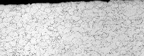


11 Metallography, etched specimens A -0, unirradiated A-1, irradiated A-6, irradiated B-2, irradiated B-5, irradiated


12 REM and REMMA, Hasrelloy A, unirradiated Ni, A-0 Ti, A-0 Overlay, A-0
 o 62 nm 63 nm")
13 Alloy B before irradiation ( L12 precipitetes composition) o 62 nm 63 nm 268 nm

14 Alloy B, unirradiated, (phase nano-structure) Al atoms are shown in red color. Precipitates of L12 structure are seen N. Wanderka, D. Isheim (2007)

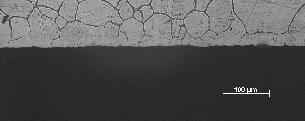
15 Irradiated in molten salt Alloy A: macrostructure a Low precipitation. Macroscopic precipitates in grains and grain boundaries are seen

16 Alloy B after irradiation (macrostructure) SEM image of the irradiated Hastelloy Grain boundaries are decorated by large precipitates No changes in the composition were measured
17 3DAP Analysis: Alloy B, initial state Ni Mo -7.2Cr Fe Al Ti Mn -0.3 Nb -0.3 Si Y (at.%) 3D reconstruction of Mo and Ni Mo-rich Clusters Composition (at.%) Al 2.37 Ni Cr 8.4 Ti 0.72 Fe 2.54 Mo 17.6 Mn Ni 20Mo Analyzed volume: 15 x 15 x 24 nm3 Ø clusters 1-3 nm The Mo-enriched clusters of Ni4Mo SRO of 2-4 nm in size are seen

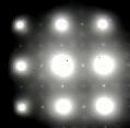
18 Alloy B: initial state (microstructure) Homogeneously distributed small spherical precipitates with L12-type ordering have been formed in the interior of the grains. The [011] zone-axis electrondiffraction pattern (inset) exibits L12 type superlattice reflections.

19 BF TEM image and corresponding SAD pattern in <100> direction of matrix of irradiated alloy B. Small precipitates, Ǿ~10nm, are formed. The supper reflexes arising from the precipitates are of D022 (Ni4Mo) short range order
 100 nm 100 nm DF TEM BF TEM No")

20 TEM Analysis: Alloy B after e- irradiation (first plate, 5066 ev/at) 100 nm 100 nm DF TEM BF TEM No spherical precipitates and no L1 2 supper reflections are visible, Only small precipitates with SRO are visible
 Spherical")

21 TEM Analysis: Alloy B after e- irradiation (second plate) Spherical precipitates are visible weak supper reflections of L1 2 and SRO 100 nm DF TEM


22 TEM/ SAD Analysis: AlloyB before and after e- irradiation B0 B131 B132 B13 3 B134 B139
23 Mechanical properties of alloys A and B Material Test temperature, C E dep, ev/atom σ B, MPa σ 02, MPa δ, % Hastelloy-A, Initial structure, aged for 50 hours at 675 C Hastelloy-A, 700 hours in salt at 650 C Hastelloy-B, Initial structure, aged for 50 hours at 675 C Hastelloy-B, 700 hours in salt at 650 C Along with high plasticity the irradiated specimens are considerably softer (see σ02 values) than those without irradiation
24 Corrosion rates of Alloys A and B at 650 C in molten fluoride salt with and without irradiation Irradiation increases the corrosion rates in molten fluoride salt by times Corrosion rate of the alloy B is proportional to the deposited energy Corrosion rate, mm/year Alloy A, E d =0 Alloy A, E d =6192 ev/at Alloy B, E d = ev/at Alloy A, E d =121 ev/at Alloy B, E d =121 ev/at Exposure in salt, hours
25 Compositional changes in surface layers of Hastelloy A ev/atom 7 6 Titanium content, at % ev/atom Chromium content, at % ev/atom 5066 ev/atom Depth, µm Redistribution of the Ti content after 700 hours exposure in molten salt without and under e-irradiation at 650 C ev/atom is the total deposited energy in surface layer 0 Depth, µm Redistribution of the Cr content after 700 hours exposure in molten salt without and under e-irradiation at 650 C
26 Loading and unloading curves during nanoindentation of C-C composite before and after irradiation in molten salt at 600 C Load (mn) before irradiation Load (mn) after irradiation Displacement (nm) Displacement (nm) Hardness and elastic modulus were to be determined from the depth of indentation according to the Oliver and Farr technique. Microscopic examination did not reveal indentations on the samples as this material has a high capacity for the elastic recovery of the original shape. Material appears to be a form of glassy carbon, which is amorphous carbon with sp 2 bonds predominating.
27 Depths dependencies of the deposited power (black circles) and the Ni Mo alloy A dpa rate (open circles)
28 Energy-weighted neutron (a) and photon (b) spectra of MSR cores with different moderator-to-fuel (C/MS) ratios. (the total neutron flux f0 =10^15 cm^-2 s^-1) Neutron flux fraction (cm -2 s -1 ) Na Neutron energy (MeV) F C / MS = 0 C / MS = 1 C / MS = 5 C / MS = 10 Photon flux fraction (cm -2 s -1 ) F K α Zr L α,β,γ U M α,β,γ U L α U L Ι Zr K α U L β U L γ Zr K β U K α U K β Na K α,β C / MS = 0 C / MS = 1 C / MS = 5 C / MS = Photon energy (MeV) (a) neutron spectra (b) photon spectra A. S. Bakai, M. I. Bratchenko and S.V. Dyuldya, 2007
29 Deposited Energy and Radiation damage in EITF and MSR s Deposited energy rate (10-3 ev/at /s) % 32.24% 58.85% 39.04% EITF MSR S1 S3 S % 45.93% S2 S4 S6 fission fragments gamma heating neutron heating 45.57% 49.88% C / MS (a) Deposited Energy Displacement damage rate, (dpa / s) 10 S1 S S3 S4 S5 S EITF % % (b) % % % % MSR % % % fission fragments neutron damage gamma damage % % % C / MS Radiation damage (Frenkel s pair generation)
30 Conclusions EITF is an efficient device for corrosion tests of G-IV candidate construction materials. EITF electron beam irradiation is capable to reproduce realistic irradiation conditions of G-IV molten salts reactor concerning the major factor affecting the Ni Mo alloys corrosion, the energy deposition in surface layers of alloys. Ni Mo alloys A and B have acceptable corrosion resistance in molten fluoride salt at 650 C. After electron irradiation in EITF for 700 h the voltammetric data provide estimation of the corrosion rate to be ~0.1 mm/year. The corrosion mode and resistance is rather sensitive to Nb and Y and presumably to other dopants. The alloy doped with Nb (0.5%) and Y (0.05%) does not show considerable intercrystalline corrosion, but its corrosion rate is sensitive to the deposited energy dose.
31 Conclusions 2 Optimization of the composition has to be made to minimize the corrosion rate. Precipitates, located mainly in grain boundaries, contain a lot of Y and apparently they work as getters mitigating the intercrystalline corrosion attack. Structure, composition and SRO of nano-scale precipitates in Ni Mo alloys is evolving under irradiation. This fact has to be taken into account at R&D of advanced materials for G-IV reactors.