Supporting Information
|
|
|
- Chad Thornton
- 5 years ago
- Views:
Transcription
1 Electronic Supplementary Material (ESI) for Journal of Materials Chemistry C. This journal is The Royal Society of Chemistry 2018 Supporting Information Facile and highly efficient fabrication of robust Ag nanowire elastomer composite electrodes with tailored electrical properties Ming Yang, a Sang Woo Kim, a Shuye Zhang, b Dae Young Park, a Chang-Woo Lee, a Yong-Ho Ko,* a Haifeng Yang, b Yong Xiao,* c Gang Chen, d and Mingyu Li b a Micro-Joining Center, Korea Institute of Industrial Technology (KITECH), 156, Gaetbeol-ro, Incheon 21999, Republic of Korea b State Key Laboratory of Advanced Welding and Joining, Harbin Institute of Technology, Harbin , China c School of Materials Science and Engineering, Wuhan University of Technology, Wuhan , China d School of Materials Science and Engineering, Harbin Institute of Technology at Weihai, Weihai , China Corresponding Authors * yonghoko@kitech.re.kr (Yong-Ho Ko) * yongxiao@whut.edu.cn (Yong Xiao) 1
2 Experimental section Materials The analytical reagents used for the synthesis of AgNW, including silver nitrate (AgNO 3 ), ethylene glycol (EG), isopropyl alcohol (IPA), ethanol, polyvinylpyrrolidone (PVP, Mw 360,000 g/mol), and ferric chloride (FeCl 3 ) were purchased from Sigma-Aldrich, USA. Membrane filters with a diameter of 47 mm containing a mixed cellulose ester with 0.2 µm pore size were purchased from Toyo Roshi Kaisha, Ltd., Japan. PDMS (including the base glue and curing agent) was purchased from Dow Corning Co., USA. Before curing, PDMS was prepared by mixing the base glue and curing agent at a ratio of 10 to 1. After vacuum defoaming, the liquid mixture was then thermally cured at 70 C for 2 h to form cross-linked solid PDMS. Synthesis of AgNWs AgNWs were synthesized using a modified FeCl 3 -mediated process; this was a one-pot process where all reagents were mixed simultaneously in a triangular flask. S1 In 50 ml of EG, 0.4g of PVP and 0.5 g of AgNO 3 were sequentially dissolved using a magnetic stirrer. The stirrer was carefully removed from the mixture after all chemicals were thoroughly dissolved. We rapidly injected 7.0 g of FeCl 3 (600 mm in EG) into the mixture and stirred it gently. Then, the mixture was immersed in a preheated silicone oil bath at 130 C for 5 h. The synthesized AgNWs had an average length of ~60 µm and an average diameter of ~70 nm. Basic characterization of the synthesized AgNW is shown in Fig. S1. 2


3 Fig. S1 (a) SEM image, (b and c) TEM images, and (d) X-Ray diffraction spectrum of AgNWs. To confirm the AgNW content in the reaction solution, a 10 ml aliquot was diluted in 500 ml of ethanol, filtered using the membrane filter with 0.2 µm pore size, dried in a vacuum chamber at 50 C for one day, and then weighed. The average of five measurements of the AgNW concentration in the fully reacted solution gave a value of 5.36 mg/ml. The AgNW deposition density was calculated by dividing this value by the corresponding area of the pattern. Fabrication of the 3-D mask Fig. S2-S4 briefly show the manufacturing process of the 3-D mask. To achieve AgNW patterns with clear edges, a smooth surface of the 3-D mask is critical. To achieve this, a twostep transfer method was developed. First, a metal plate (SUS in this case) with the desired concave pattern was fabricated by mechanical cutting. The depth of the groove was mm and the surface of the metal plate was carefully polished. Second, we cast a layer of epoxy resin (~5 mm in thickness) on the surface of the metal mold and cured it at room temperature for one 3

 on the surface of the epoxy resin mold and cured it at 70 C for 1 h after vacuum de-foaming to form")
4 day. Third, the assembled mold was immersed in 1000 ml HCl (~37 wt.%) for several days to completely dissolve the metal plate. Then, stainless steel pins with a height of >10 mm and diameter of mm (depending on the sample type) were attached or nailed on top of the pattern in the form of array. Next, we cast a layer of PDMS (~5 mm in thickness) on the surface of the epoxy resin mold and cured it at 70 C for 1 h after vacuum de-foaming to form crosslinked solid PDMS. Finally, we carefully pulled out the steel pins and peeled off the PDMS from the epoxy resin mold. Fig. S2 Process for fabricating the 3-D masks. 4
 Casting epoxy resin and curing. (c) Epoxy resin mold with convex grid pattern Fig.")
 Assistant mold. (b) Inserting steel pins in the corresponding holes.")
 Casting PDMS into the resin mold, followed by curing, removing the steel pins, and peeling")
5 Fig. S3 Process for fabricating the resin mold. (a) Mechanical mold with grid grooves. (b) Casting epoxy resin and curing. (c) Epoxy resin mold with convex grid pattern Fig. S4 Photographs of the fabrication process of the 3-D PDMS mold and the AgNW pattern made by the 3-D PDMS. (a) Assistant mold. (b) Inserting steel pins in the corresponding holes. (c) Inverting the mold with pins on the cross-section of the resin mold. (d) Casting PDMS into the resin mold, followed by curing, removing the steel pins, and peeling off the 3-D PDMS. (f) Vacuum filtration system using 5
6 the 3-D PDMS as a mask. (g) AgNW pattern on the filtration filter. (h) AgNW pattern transferred to the PDMS. Fabrication of patterned AgNW layer on membrane filters and on PDMS To fabricate the AgNW patterns, 10 ml of the reaction solution was diluted in 43.6 ml of ethanol to make a diluted solution of 1 mg/ml. A certain quantity of the diluted AgNW solution was added to 250 ml of ethanol and filtrated using the vacuum filtration system with 3-D PDMS, as shown in Fig. S4f. During filtration, the filter was left under vacuum for 3 5 min after all the solution was filtered out. Generally, the filter was physically attached to the bottom surface of the 3-D PDMS mask after filtration. Then, the 3-D PDMS mask was transferred onto a temporary substrate made of smooth glass or PE with double-sided tape (Scotch, 3M) attached to the surface. After applying a moderate manual force, the 3-D PDMS mask was removed with the filter well adhered to the transient substrate. Before casting the PDMS, the filter was placed on a hot plate at 50 for 1 h to dry completely. Then, some PDMS was cast on the filter and cured at 70 for 2 h. Due to the rough surface of the membrane filter, it is difficult to peel off the cured PDMS if the AgNW/PDMS is too thin. To obtain intact AgNW/PDMS samples, the thickness of the cast PDMS should be >0.5 mm. Characterization The microstructure of the samples was analyzed using a Hitachi-S 4800 field-emission scanning electron microscope (FE-SEM) with a 15 kv electron source. The sheet resistance values of the AgNW/PDMS nanocomposite films with different geometries were measured using a 4-point probe sheet resistance meter (Chang Min CMT-SR1000N) using the recommended calibration factors for the corresponding geometry. The quoted sheet resistance 6
7 values are an average of 15 measurements per sample. A custom-designed stretch-release test module consisting of a motorized stage, grip module, and source meter (3706, Keithley Instruments, USA) was used to investigate the electromechanical properties during axial stretching of the AgNW electrodes. The cyclic stretch/release test rate was 1 mm/s. The initial length of the region under stretching was set at 20 mm. [S1] J. Jiu, J. Wang, M. Nogi, T. Sugahara, S. Nagao, H. Koga, K. Suganuma, E. Nakazawa, H. Uchida, K. Shinozaki, Facile synthesis of very-long silver nanowires for transparent electrodes, J. Mater. Chem. A 2 (2014)

8 Fig. S5 Sheet resistance and thickness of AgNW films on membrane filters or PDMS substrates as functions of the AgNW deposition density. The inset shows a photograph of the sample. 8


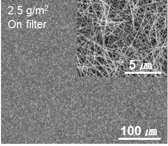


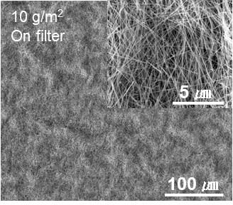


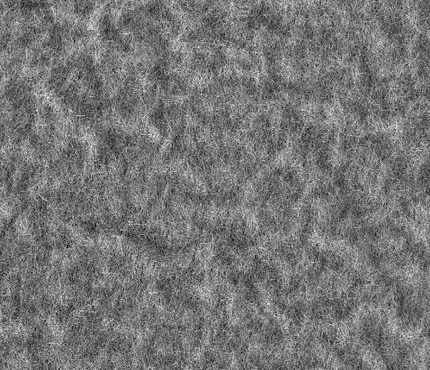


9 Fig. S6 Top-view SEM images of the microstructure of AgNW/PDMS films prepared with different AgNW deposition densities. 9


10 Fig. S7 Sheet resistance of the AgNW electrodes fabricated on (a) membrane filters and transferred to (b, c) PDMS substrates. 10

11 Fig. S8 Resistance of AgNW/PDMS electrodes as a function of the applied strain from 0 to 80%. 11


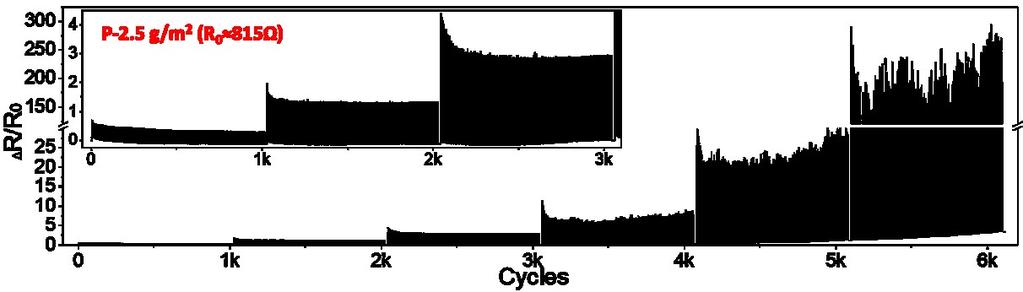

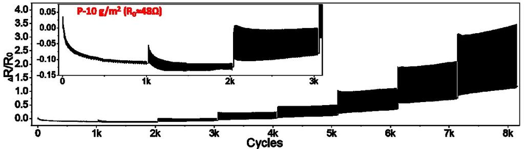


12 Fig. S9 Normalized transient resistance of PDMS/AgNW/PDMS strain sensors during 1000 tensile stretch/release cycles with successive peak strains of 10%, 20%, 30%, 40%, 50%, 60%, 70%, and 80%. 12
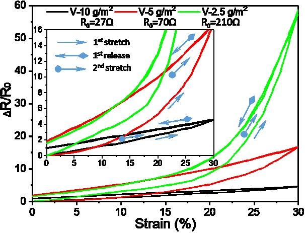


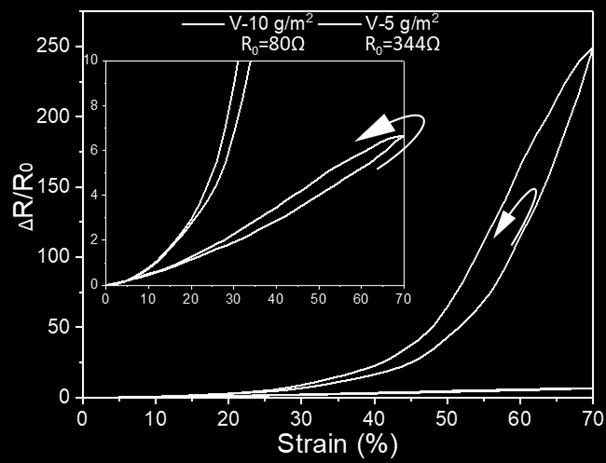
13 Fig. S10 Normalized resistance change of the PDMS/AgNW/PDMS stretchable electronics as a function of tensile strain at the 1 st and 2 nd cycle. 13


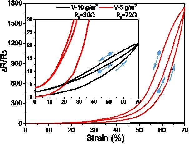
14 Fig. S11 Normalized resistance change of the PDMS/AgNW/PDMS stretchable electronics as a function of tensile strain at the 500 th cycle. 14

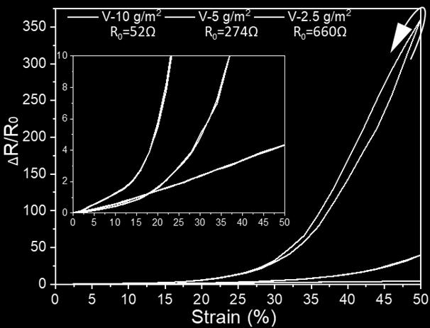
15 Fig. S12 Gauge factor as a function of strain for V- and P-samples with different AgNW deposition densities. 15


16 Fig. S13 Schematic diagram of V- and P-samples under tensile strain. 16