Status and Further Potentials of CIS and Related Solar Cells. Hans-Werner Schock Helmholtz Centre Berlin, Division Solar Energy
|
|
|
- Austin Barrett
- 5 years ago
- Views:
Transcription

1 Status and Further Potentials of CIS and Related Solar Cells Hans-Werner Schock Helmholtz Centre Berlin, Division Solar Energy WPSEC 5-25 EUPVSEC Valencia Spain 2010

2 CIS History In memoriam Prof. Werner H. Bloss, winner of the Becquerel price in 1991 who was one of the most active pioneers of renewable Energy research in Europe 2
3 What is special about CIGS? What is special about Cu(In,Ga)(S,Se) 2? - a multinary compound with high flexibility Why does it work as a PV material? What are the limits? 3
4 Just a diamond (silicon) like structure From II-VI to I 2 -II-IV-VI 4 sphalerite chalcopyrite kesterite II-VI I-III-VI 2 I 2 -II-IV-VI 4 easy to form best efficiency cheap elements CdTe Cu(In,Ga)Se 2 Cu 2 ZnSnS 4 more difficult 4
5 What is special about CIGS? high optical absorption secondary phases have commensurate structures, i.e. phase segregations do not cause severe distortion during growth electronic properties of CuIn(Ga)Se 2 extremely tolerant to defects i.e. deviations from stoichiometry, crystallographic imperfections and grain boundaries due to fortunate defect structure Cu-vacancies just lower the valence band: deviations from stoichiometry i.e. Cu/In+Ga ratios form neutral defect complexes therefore: high level of deviations from stoichiometry and impurities can be tolerated, in particular at only moderate efficiencies (< 15%). but: control of electronic properties by extrinsic doping is difficult or impossible - pn junctions have to rely on intrinsic defects 5

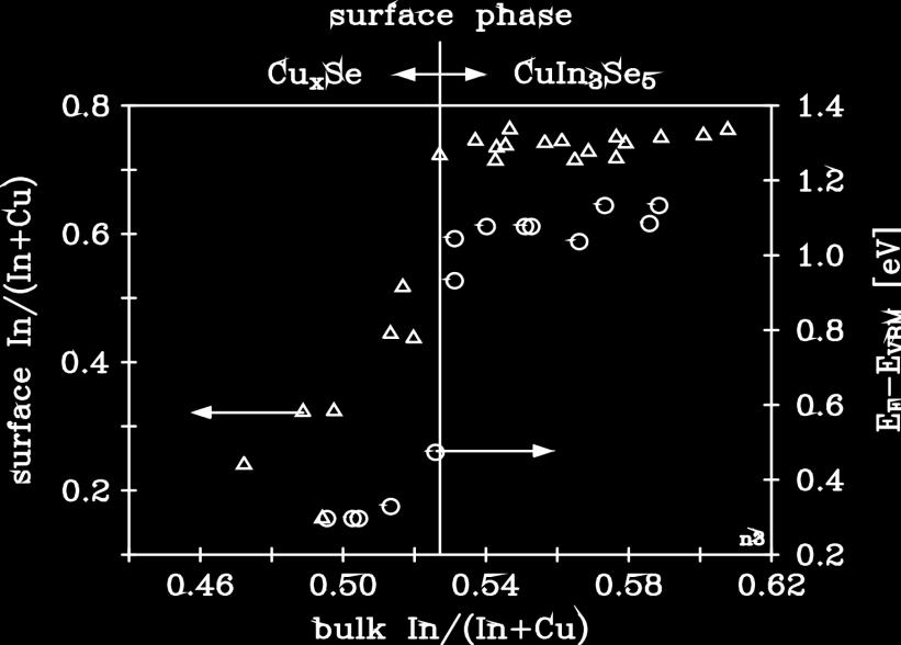
6 The favourable surface of CIS 6

 Cu 2 In 4 Se 7, CuIn 3 Se 5 S.B.")
7 Defect-phases and stability electronic properties not not strongly dependent on deviations from stoichiometry in CuInSe 2 : Cu/In+Cu can range Defect pair: electronically neutral 2V Cu - + In Cu ++ energetic position in valence- or conduction band structure element of the defect phases with larger bandgap (lower valence band) Cu 2 In 4 Se 7, CuIn 3 Se 5 S.B. Zhang, S.H. Wei, A. Zunger, H. Katayama-Yoshida, Phys. Rev. B. 57, 9642,

8 The EUROCIS story Cross section of the first efficient CuInSe 2 solar cell Eff. = 14.8% Voc=513mV FF = Jsc = 40.4 ma/cm 2 L. Stolt, J. Hedstrom, J. Kessler, M. Ruckh, K. O. Velthaus, and H. W. Schock, "ZnO/CdS/CuInSe 2 THIN-FILM SOLAR-CELLS WITH IMPROVED PERFORMANCE," Applied Physics Letters 62 (6), (1993). 8

9 1st CIS project % cell EUROCIS projects NEW POL ENSCP IPE USTL UNIV PR 9
10 EUROCIS 4/90-9/92 CIGS: 14.8 %, EUROCIS projects RIT NEW POL RUG-LEM ENSCP IPE CEM 10
11 EUROCIS projects EUROCIS II 11/92-10/95, CIGS: 17.6 %, Module 10x10cm %, KTH MC St Petersburg NEW POL Minsk Voronesh RUG-LEM Warsaw Kharkov ENSCP IPE ZSW AFIF Bukarest CEM Sofia UCM CIEMAT ENEA 11
12 EUROCIS projects EUROCIS M 4/97-9/99, CIGS: 17.6 %, Module 10x10 cm %, Module 30x30 cm 2 UU/ASC NSE MC ENSCP IPE ZSW 12
13 PROCIS 1/01-12/03 Technology Transfer EUROCIS projects UU/ASC MC ENSCP EDF IPE ZSW/WS ETH 13
14 LARCIS 11/ /2009 Large Area Technology Transfer EUROCIS projects UU/ASC Solibro HZB ENSCP EDF SGR ZSW/WS ETH UB-EME 14
15 Present developments Efficiency Cu(InGa)(S,Se) 2 - CIGS absorber layers Heterojunctions 15
16 efficiency [%] Development of the efficiency of thin film cells in the lab Si CIGS CdTe a-si no light soak Cu2S CuInS2 prototypes modules in production year CIGS: still continuous improvement! CIGS is the high efficiency thin film option 16
17 Layer sequence of a CIGS solar cell "vacuum" "non vacuum" sputtering/cvd PVD, CVD/CBD TCO window pn (hetero)-junction APCVD, chemical? chemical PVD, selenisation/ sulfurisation Mo sputtering (PVD, SiN, SiO x ) glass/foil Absorber back contact/ (barrier) substrate electrodeposition/printing selenisation/sulfurisation PVD Mo, Cr... (sol gel, SiN, SiO x, Cr, ) glass /foil substrate structure enabling flexible cells by role-role manufacturing, 17
18 Layer sequence of a CIGS solar cell "vacuum" sputtering/cvd PVD, CVD/CBD TCO window pn (hetero)-junction "non vacuum" APCVD, chemical? chemical PVD, selenisation/ sulfurisation Mo sputtering (PVD, SiN, SiO x ) glass/foil Absorber back contact/ (barrier) substrate electrodeposition/printing selenisation/sulfurisation PVD Mo, Cr... (sol gel, SiN, SiO x, Cr, ) glass /foil 18
19 CIGS technology quo vadis? CIGS deposition: will it converge? actual production capacity 300 MW 1000 MW single crystal single source evaporation co-evaporation co-sputtering substrates: glass, metal/polymer foils precursor based methods: sputtering printing anneal electrodepos. RTP of stacks and/or Se/S,H 2 S/H 2 Se new process? cost <0.5 /W 20% module efficiency glass or flexible actual production capacity 300 MW diversification of processes increases 2000 MW

 In Cu Se,S In,Ga Cu anneal Cu(In,Ga)(S)Se 2 Reaction of")
20 Deposition process - Cu(In,Ga)(S,Se) 2 films Co-evaporation: - constant rate: Cu In Ga Se S metal films and gas Se,S H 2 Se precursor based methods H 2 S reaction of binary compounds with gas phase Cu Se In Ga Se S multi stage processing Cu-rich-In-rich In/Ga, S/Se gradients In x Se(S) In Cu Se,S In,Ga Cu anneal Cu(In,Ga)(S)Se 2 Reaction of elemental layers 20
21 CIGS Technology quo vadis? CIGS junction formation: will it converge? CdS, (Cd,Zn)S evaporation buffer layer TCO chemical bath sputtering deposition ZnO CdS - In,S(OH) - ZnS(OH) buffer layer sputtering TCO CVD ZnO cost <0.5 /W 20% module efficiency glass or flexible
22 Prospects Efficiency potential Wide bandgap and tandem cells New compounds 22
23 CIGS high efficiency thin films ZSW 1 NREL 2 HZB 3 Best values V OC (mv) J SC (ma) FF (%) η (%) ? like crystalline wafer cells, just planar structures! 1 ZSW Press release I.Repins et al. in Progress in Photovoltaics: Research and Applications 16(3): , HZB, 24th PVSEC Hamburg 2010 and this conference 23
24 Wide-gap chalcopyrites >20% device efficiency has been reached only for low bandgap (<1.2 ev) 1.2 V Cu(In,Ga)Se 2 single layer bilayer Cu(In,Ga)(Se,S) 2 CuGaSe 2 recent results on Cu(In,Ga)S 2 S. Merdes et. al. Open circuit voltage V oc (V) CuInSe 2 20 %eff line: Eg V Band gap energy (ev) min = 9% CuInS 2 CuGaSe 2 High Efficiency, High Voltage Solar Cells by Band Gap and Defect Engineering in Cu(In,Ga)(S,Se)2 Chalcopyrite Semiconductors, H. W. Schock, et al, Proc. 16th Europ. PV Solar En. Conf, Glasgow,
25 High efficiency concepts > 25% efficiency Tandem structures? 1.7 ev 1.0 ev highly efficient wide gap cell needed tunnel heterojunction The challenge of monolithic tandem structures: - solve the problem of wide gap cells - self organizing structure and interfaces substrate or superstrate? 25
, pp. 341 346 YEAR Friedlmeier, T. M., H.")
26 EFFICENCY (%) Kesterite compounds - Progress in efficiency Cu 2 SnZnSe 4 T: K. Todorov, K: B. Reuter, D. B. Mitzi, Adv. Mat., 22, p E156 - E159, Published Online: 8 Feb 2010 Monograins, E. Mellikov et al 5 Cu 2 SnZnS 4 HZB 0 Kesterite publications K. Ito and T. Nakazawa. In: Proc. 4th Int. PVSEC (1989), pp YEAR Friedlmeier, T. M., H. Dittrich, et al. (1998). Iop Publ.,Ltd. 152: Katagiri, H., K. Jimbo, et al. (2008). Applied Physics Express 1(4). Kesterites make slow but steady progress 26
27 Conclusions Chalcopyrite semiconductors Favourable properties facilitate realisation of efficient photovoltaic devices High efficiency devices in the laboratory do not differ significantly from devices in commercial modules. CIGS is very tolerant to deviations from stoichiometry By proper choice of reaction path for the formation of thin films high quality material can be realized with easy control of processes. In spite (or because) of apparent complexity there many ways for upscaling of production 27

28 Acknowledgements Becquerel Committee all my former colleagues at IPE the colleagues who participated in the EUROCIS consortia the colleagues at ZSW and Würth Solar who pushed for production the colleagues at the Helmholtz Centre who made my new start in Berlin most convenient all the colleagues and friends of the international PV community My Wife and my Children who always provide me a very stable mental background in demanding times in the amphitheater of PV 28
29 CIGS Technology quo vadis? custom equipment engineering solutions for perfect process control coevaporation the compromise: adapted standard equipment adapting process to high throughput standard equipment sequential processes high throughput high quality 29
30 High efficiency concepts Intermediate band absorber materials would be an ideal solution for simple high efficiency devices new material science - needs proof of concept Host Bandgap CuGaS 2 :M film M = Sn, Fe, Ti First experiments show photocurrent from impurities - but V oc gets lower Martí, D. Fuertes Marrón, and A. Luque, J. Appl. Phys. 103, (2008). Modeling suggests optimum host bandgap 2.4 ev. Cu(In,Ga)S 2 system covers bandgap range ev