Soldering. Important steps in making a good soldered joint: design of acceptable joint. selection of correct solder metal for the job
|
|
|
- Anastasia Lloyd
- 5 years ago
- Views:
Transcription
1 Soldering Brazing-type operation where filler metal melting point is below 450 o C (840 o F). Typically used for connecting thin metals, electronic components (mostly where higher temperature should be avoided) Important steps in making a good soldered joint: design of acceptable joint selection of correct solder metal for the job selection of proper flux cleaning surfaces application of flux, solder and heat to fill joint by capillary action removing residual flux if required. Lecture 10 1
2 Solder Joint Design Used for wide variety of sizes, shapes and thickness joints. (clearance) Extensively used for electrical couplings and gas/air-tight seals. Shear strength is usually less than 2MPa. So if more strength required usually combined with other form of mechanical joint as seam-lock. Avoid butt joints, and soldering where joint is subject to peeling. Parts need to be held firmly until solder is completely solidified. Flux should be removed after soldering (method depends on type of flux; water, alcohol etc.). Lecture 10 2
 Lecture")
3 Metals to be Joined Copper, silver, gold, tin plated steels easily joined Aluminum (has strong oxide film) so difficult to solder unless using special fluxes and modified techniques (used in automotive radiators) Lecture 10 3
4 Solder Metals Usually low MP alloys Lead-Tin alloys (+ antimony 0.5%) low cost, reasonable mechanical properties. Good knowledge base plumbing, electronics, car-body dent repair, radiators. Tin is more expensive than lead, so lower tin compositions used unless lower melting point, higher strength, higher fluidity required. High melting point higher lead content (cheaper) Mushy wiping solder has 30-40% tin. Low melting point solder has eutectic composition (62%Sn - 38%Pb) fast melting, fast freezing, high strength. Lecture 10 4
5 Solder Metals Lead-free solders - Used where lead toxicity may be a problem. (water supplies etc). Other alloys include Tin-antimony (higher melting points) Bismuth Tin-indium Lecture 10 5
6 Soldering Fluxes Same principles as brazing so surfaces must be clean; mechanical or chemical cleaning. Fluxes remove surface oxides: Corrosive: muriatic acid, zinc/ammonium chlorides. Al, steels, copper, brass, bronze. Non-corrosive: rosin (residue after distilling turpentine), good for copper, brass, tin or silver-plated surfaces Heating for Soldering Similar to brazing, (furnace and salt bath heating is not usually used) Wave soldering is used for wires while dip soldering for auto parts Hand soldering is done by solder iron and oxy fuel torch Lecture 10 6

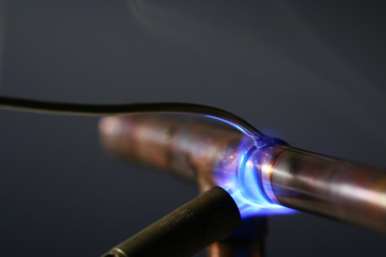

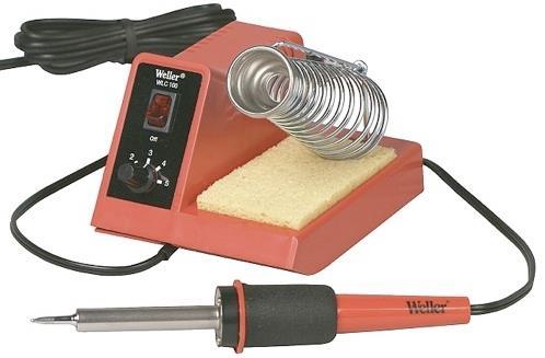
7 Soldering Heat 7
8 MECH 423 Casting, Welding, Heat Treating and NDT Time: W _ F 14:45-16:00 Credits: 3.5 Session: Fall Adhesive & Mechanical Fastening 8
9 Adhesive Bonding 9
10 Adhesive Bonding Inexpensive and weigh less than fasteners for similar strength joints provide thermal and electrical insulation; act as a damper to noise, shock, and vibration; stop a propagating crack; and provide protection against galvanic corrosion when dissimilar metals are joined Seal against moisture, gases, and fluids; Offer corrosion resistance Most adhesives can be applied quickly, and useful strengths are achieved in a short period of time. (2 seconds!) Surface preparation may be reduced - bonding can occur over an oxide film, and rough surfaces are good - increased contact area. Tolerances are less critical since the adhesives are more forgiving than alternative methods of bonding Smooth contours are obtainable, (no holes required cf. bolts). 10
11 Adhesive Materials and Properties Biggest advantage is in load distribution, unlike mechanical fasteners Non metallic (adhesive) material is used to join surfaces Can be thermoplastic or thermosetting resins, elastomers, ceramics Applied as drops, beads, pellets, tapes, coatings (liquids, pastes ) Curing can be influenced by heating, radiation or light, catalyst or chemical reactions Different applications of adhesive fastening Heavy duty or Load bearing (structural adhesive) Light duty or fixturing (mainly to hold pieces together) Sealing (forming liquid or gas-tight joints) Due to load bearing nature of structural adhesive, strength and rigidity of the adhesive material over a period of time is important 11
12 Adhesive Materials and Properties 1. EPOXY oldest and more common (single or two component) single component needs heat to cure, two component cures at RT 2. CYANOACRYLATES - single component cures at RT, moisture promotes curing < 2s 3. ANAEROBICS - single component, remains liquid in air, shut of O in joints, cures by polymerizing in the presence of Fe or Cu. 6 to 24 hrs to attain useful strength 4. ACRYLICS - two component can be applied and stored separately. Once joined, they cures at RT. thermoplastic 5. URETHANE used in low temp service <65 C 6. SILICONE resistant yet flexible joint. Cures from moisture on surface 7. HIGH-TEMPERATURE ADHESIVES expensive as silicone, good for use clost to 300 C. slow curing. Aerospace applications 12
13 Adhesive Materials and Properties 8. HOT MELTS - not considered to be true structural adhesives, but are being used to transmit loads, mostly in composite mat l assemblies They are thermoplastic resins - solid at room temperature but melt abruptly when heated into the range of 200 to 300 F (l00 to 150 C) Applied as heated liquids to form bond as the molten adhesive cools Or position the adhesive in the joint prior to operations (paint bake process) in automobile manufacture. while baking, the adhesive melts, flows into seams, and seals against corrosive moisture entry The hot melts provide reasonable strength within minutes, but do soften and creep when exposed to elevated temperatures and become brittle when cold. 21
14 Adhesive Materials and Properties 22
15 Design Considerations 1. What materials are being joined? What are their porosity, hardness, & surface conditions? Difference in thermal expansions (contractions) 2. How will the joined assembly be used? What type of joint is proposed, what will be the bond area, and what will be the applied stresses? How much strength is required? Will there be mechanical vibration, acoustical vibration, or impacts? 3. What temperatures might be required to effect the cure, and what temperatures might be encountered during service? (highest temperature, lowest temperature, rates of temperature change, frequency, duration of exposure to extremes, properties required, and differential expansions or contractions.) 23

16 Design Considerations 4. Will there be subsequent exposure to solvents, water or humidity, fuels or oils, light, ultraviolet radiation, acid solutions, or general weathering? 5. What is the desired level of flexibility or stiffness? How much toughness is required? 6. Over what length of time is stability desired? What portion of this time will be under load? 7. Is appearance important? 8. How will the adhesive be applied? What equipment, labor, and skill are required? 9. What will it cost? 24


17 Design Considerations 25
18 Adhesive Bonding Advantages 1. Most material/combination can be joined (size, shape, and thickness). 2. For most adhesives, low curing temperatures, (usually <180 C). Heatsensitive materials can be joined without damage and HAZ. 3. Foils can be joined to each other or to heavier sections. When joining dissimilar materials, the adhesive provides a bond that can tolerate the stresses of differential expansion and contraction. 4. Adhesives bond the entire joint area good load distribution and fatigue resistance; stress concentrations are avoided (unlike screws). Total joint strength comparable with alternative methods. (Shear strengths of industrial adhesives > 20MPa or 300 PSI) 5. Additives can enhance strength, increase flexibility, provide resistance to various environments. 26
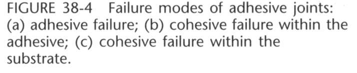
19 Adhesive Bonding Disadvantages 1. No universal adhesive. Selection is complicated by available options. 2. Most adhesives are not stable above 350 F (180 C). (Max 260 C). 3. High-strength adhesives are often brittle (poor impact properties). Resilient ones often creep. Some become brittle at low temperatures 4. Long-term durability and life expectancy are difficult to predict. 5. Surface preparation and cleanliness, adhesive preparation, and curing can be critical for consistent results. Adhesives are sensitive to grease, oil, moisture. Surface roughness and wetting must be controlled. 6. Difficult to determine the quality by traditional NDT techniques. 7. Adhesives contain toxic chemicals/solvents, or produce upon curing. 8. Many structural adhesives deteriorate under certain operating conditions, UV light, ozone, acid rain, moisture, and salt. 9. Adhesively bonded joints cannot be readily disassembled. 27
20 Mechanical Fastening 28
21 Mechanical Joining Methods Often based on localized, point-attachment processes, in which the join is provided by a nail, a rivet, a screw or a bolt. These joints depend on residual tensile stresses in the attachment to hold the components in compression. The joint is usually formed by an ordered array of pointattachments, rivets at the edge of a ship's plate, or the uniformly spaced bolts around a pressure vessel flange. Mechanical joints are also made along a line of attachment, such as that formed when a piece of sheet is bent to form a cylinder (a paint can, for example) and the two edges are joined with an interlock seam. 29
22 Mechanical Fasteners Here too the residual stresses (tensile around the circumference of the can, compressive along the joint) ensure integrity of joint. Many mechanical joints are designed for ease of assembly and disassembly (for example, bolted joints). The effectiveness of mechanical fasteners depends upon The material of the fastener, Fastener design (including the load-bearing area of the head) Hole preparation, The installation procedure. The desire is to achieve uniform load transfer, minimum stress concentration, and uniformity of installation torque or interference fit. 30
23 Mechanical Fasteners Integral fasteners: formed areas of a component that interfere or interlock with other components - most commonly found in sheet metal products: lanced/shear-formed tabs, extruded hole flanges, embossed protrusions, edge seams, and crimps. e.g. beverage can lids, tabs etc. 31
24 Mechanical Fasteners Discrete fasteners: separate pieces used to join primary components: bolts, nuts, screws, nails, rivets, quick-release fasteners, staples, and wire stitches. Over 150 billion discrete fasteners - annual consumption in the US, 27 billion by auto industry. (ANSI BI8.12.) The fasteners are easy to install, remove, and replace. Various finishes and coatings can be applied to withstand a multitude of service conditions. 32
25 Mechanical Fasteners Shrink and expansion fits: dimensional change introduced to one or both of the components by heating or cooling (heating one part, heating one and cooling other, or cooling one). Assembled and a strong interference fit is established when temperature uniformity is restored. Joint strength is exceptionally high. Can be used to produce a prestressed condition in a weak material; to replace costly stronger one. Similarly, a corrosion-resistant cladding or lining can be easily provided to a less-costly bulk material. Press fits: similar to above but using mechanical force. 33
26 Mechanical Fasteners - Advantages 1. Ease of disassembly and reassembly. (threaded fasteners) and semipermanent fasteners (such as rivets) can be drilled out. 2. The ability to join similar or different materials in different sizes, shapes, and joint designs. Some joint designs, such as hinges and slides, permit limited motion between the components. 3. Low manufacturing cost compared to the components being joined. They are readily available in a variety of mass-produced sizes. 4. Installation does not adversely affect the base materials as with techniques involving the application of heat and/or pressure. 5. Little or no surface preparation or cleaning is required. 34
27 Role of Residual Stress Mechanical joints use compressive residual stresses across the join in order to maintain the components in contact. They therefore require a balancing tensile stress elsewhere in the system. These tensile stresses may either be in the fastening (nails, bolts or rivets), or in the components themselves (the interlock seam). 35
28 Manufacturing Concerns Often require aligned holes for mechanical fasteners. Many ways to make holes; drilling, punching, chemical machining, lasers etc. Each produces holes with characteristic features; surface finish, tolerance, properties etc. If bolts need nuts then two-sided access is required (if threaded hole one side only). Self-tapping screws (harder screws or softer materials). Stapling is quick, cheap method that does not require prior hole. Rivets give good strength but are semi-permanent. Snap fits require material is sufficiently elastic. 36
29 Design and Selection Must consider many factors including possible joint failure as fasteners are vulnerable sites. Joints usually fail due to oversight in: Design of fastener and its method of manufacture. Material used for fastener. Joint design. Means and details of installation. E.g. Insufficient strength or corrosion resistance, (galvanic corrosion is common with dissimilar metal fasteners). Non-metallic fasteners (nylon, fiberglass) can sometimes be used at low stresses. 90% of cracks in airframes originate at fastener holes (stress raisers) and fasteners fail by fatigue. 37
30 Problems worsen if too loose or too tight. Rolled threads and formed heads are better than machined and fillets are important between head and shank of bolts. Design and Selection 38
31 MECH 423 Casting, Welding, Heat Treating and NDT Time: _ T _17:45-20:15 Credits: 3.5 Session: Fall Welding Joints & Metallurgy 39
32 Flow of Heat in Welds Heat (energy) is introduced into workpiece to cause melting during fusion welding. Not all heat contributes to melting. Some conducted away raising temperature of surrounding material causing (unwanted) metallurgical & geometrical changes - AKA HAZ. How the heat is distributed directly influences: the rate and extent of melting; (affects weld volume, shape, homogeneity, shrinkage, distortion, related defects). the rate of cooling and solidification; (solidification structure, related properties). the rate of heating and cooling in the HAZ; (thermally induced stresses, cooling rate in solidification zone, structural changes in HAZ, distortion, residual stresses). 40
33 Weld Zones Prediction A fusion weld produces several distinct microstructural zones in both pure metals and alloys. Fusion zone, FZ: portion of metal that is melted during welding (above Tm or TL for alloy). Partially Melted Zone, PMZ: for an alloy where temperature is between TLiquidus and TSolidus. (No PMZ in pure metal). Heat Affected Zone HAZ: portion of base material that was not melted but whose properties are affected by heat of welding (phase transformation, reaction). Unaffected Base Material UBM: portion of base material which has not been affected by welding heat. 41
34 Weld Zones Prediction The various microstructural zones formed in fusion welds between a pure metal (right) and an alloy (alloy). Schematic of the distinct zones in a fusion weld in a pure metal (a) and an alloy (c) as these correspond to phase regions in the hypothetical phase diagram shown (b). 42
35 Simplified welding equations. Peak Temperatures in solid metal: T P 1 T e H Chy net T m 1 T 0 where: T 0 = temperature of workpiece at start of welding (K) T P = Peak temperature at distance y from fusion boundary (K) T m = melting temperature (or liquidus) of metal being welded (K) = density of metal (g.m -3 ) C = specific heat (J.g -1.K -1 ) H net = heat input (J.m -1 ) = q/v = EI/v for arc welding processes h = thickness of base material (m) e = base of natural logarithms (2.718) y = distance form fusion zone (= 0 at the fusion zone, where T P = T m ) (m) 43
36 Solidification rate The rate at which weld metal solidifies can have a strong effect on microstructure and properties. Solidification time, S t, in seconds: S t LH net 2 2 k C Tm T 0 where: L = Latent heat of fusion (J/m 3 ) T 0 = temperature of workpiece at start of welding (K) T m = melting temperature (or liquidus) of metal being welded (K) k = thermal conductivity (J.m -1.s -1. K -1 ) = density of metal (g.m -3 ) C = specific heat (J.g -1.K -1 ) H net = heat input (J.m -1 ) = q/v = EI/v for arc welding processes 44
37 Cooling Rates Final metallurgical state of FZ and HAZ is primarily determined by cooling rates. Affects fineness/coarseness of grains, homogeneity, phases, microconstituents etc. Especially in steels where some phase transformations are dependent on cooling rate (fast cooling can produce hard, brittle martensite). For a single pass in a butt joint between thick plates (> 6 passes) of equal thickness: where: 2 k TC T R H R = cooling rate at the weld centreline (K/s) T 0 = initial temperature of workpiece (K) T C = temperature at which cooling rate is calculated (K) k = thermal conductivity (J.m -1.s -1. K -1 ) H net = heat input (J.m -1 ) = q/v = EI/v for arc welding processes net
38 For thin plates ( < 4 passes): R h 2 k C T C T H net 2 0 where: R = cooling rate at the weld centreline (K/s) T 0 = initial temperature of workpiece (K) T C = temperature at which cooling rate is calculated (K) k = thermal conductivity (J.m -1.s -1. K -1 ) = density of metal (g.m -3 ) C = specific heat (J.g -1.K -1 ) C = volumetric specific heat (J.m -1.K -1 ) H net = heat input (J.m -1 ) = q/v = EI/v for arc welding processes Note: increasing the initial temperature, T 0, (by preheating) decreases the cooling rate,r. 46
39 Schematic of the effect of weldment and weld geometry on the dimensionality of heat flow: (a) two-dimensional heat flow for fullpenetration welds in thin plates or sheets; (b) two-dimensional heat flow for full-penetration welds with parallel sides (as in EBW and some LBW); (c) three-dimensional heat flow for partial- penetration welds in thick plate; and (d) an intermediate, 2.5-D condition for near-full-penetration welds. 47
40 Weld Joint Configuration Heat flow in weld is affected by size and shape of weld. Surfacing or Bead welds, made directly, no surface preparation. Used for joining thin sheets, adding coatings over surfaces (wear resistance) Groove Welds full thickness strength, done as V, Double V u, and J (one side prepared). The type of groove depends on the thickness of the joint, weld process and position Fundamental types of welds, including (a) groove, (b) fillet, (c) plug, and (d) surfacing. 48
41 Weld Joint Configuration Fillet Welds, used for tee, lap or corner joints. No edge preparation. Size of the weld is measured by the largest 45 right triangle that could be drawn in the weld cross section. Plug Weld attach one part over another replacing rivets are bolts. Normally a hole is made on the top plate and welding done at the bottom of the hole Five basic weld designs and some typical joints are shown in the figure Fundamental types of welds, including (a) groove, (b) fillet, (c) plug, and (d) surfacing. 49
42 Weld Joint Configuration Inserts are used in pipelines or other places where welding is restricted to one side only 50
43 Weld Joint Configuration Type of loading will decide the type of Five basic weld designs: (a) butt, (b) corner, (c) edge, (d) lap, (e) tee. joint, to prevent failure Accessibility and cost are other considerations Cost is affected by the amount of weld metal, type of weld equipment, speed and ease of welding Some typical weld joint variations. 51
44 Weld Joint Configuration (a) Single V, (b) double V, (c) single U, (d) double U joints. Require filler metal. (a) Full penetration, (b) partial penetration, (c) continuous, (d) intermittent welds. 52
45 Weld Joint Configuration 53
46 Weld Joint Configuration Straight butt joints do not require filler metal as long as faces abut tightly (gaps less than 1.5 mm) usually requires machined surface (not sawn) GTAW, PAW, LBW, EBW. Other joint configurations (V, double V, J, U etc) require filler metal and preparation is made by cutting, machining etc. SMAW, FCAW, GMAW, SAW. Likewise with corner and edge joints. Some can be done without preparation, others require machining. 54
.")
47 Weld Design Considerations Welding is a unique process producing monolithic structures (one-piece from 2 or more pieces welded together) If pieces joined together, and if there is a crack in one, it does not propagate to other piece normally. In case of welding, since it becomes single piece, crack can propagate through to other piece. (The crack can initiate in the weld or otherwise). - reflects the monolithic nature of welding process. Another consideration is small pieces may behave differently compared to larger pieces of steel (shown in figure) 55
48 Weld Design Considerations Joint designed primarily for load-carrying ability. Variable in design and layout can affect costs, distortion, reliability, inspection, corrosion, type of defects. Select design that requires least amount of weld metal. (minimizes distortion, residual stresses). 1. Where possible use square grooves (cheaper) and partial penetration (helps maintain dimensions unmelted metal in contact) except where stress raisers cannot be tolerated (fatigue). 2. Use lap and fillet (instead of groove) welds where fatigue is not a problem (cheaper). 56
49 Weld Design Considerations 3. Use double-v double-u (instead of single-v or U) for thick plates (reduces weld metal vol.; controls distortion & balances heat input). 4. For corner joints in thick plates where fillet welds are inadequate, bevel both plates to reduce tendency for lamellar tearing. 5. Design so weld can be accessed and inspected. 6. Over designing is a common problem in welding that should be avoided (causes excessive weight and costs as a fillet weld side increases x2 the weld metal increases by x4 57
50 Weld Metallurgy Remember(?) HEAT TREATMENT and how various microstructures + properties can be obtained by different cooling rates. CASTING - liquids shrink on solidifying, type of grain structures, segregation, etc. WELDING - combines both usually: Melting + solidifying of weld pool Varying heating/cooling rates 58
 Fusion welding can be viewed as a casting with small amount of molten metal Resultant structure can be understood if it is analyzed as casting and subsequent heat")
51 Weld Metallurgy Figure shows a welding where Metals A and B are welded with Metal C as a backing plate and Metal D as a filler Molten pool is a complex alloy of ABCD held in place by metal mould (formed by solids) Fusion welding can be viewed as a casting with small amount of molten metal Resultant structure can be understood if it is analyzed as casting and subsequent heat treating 59


52 Weld Fusion Zone The composition of the material in the weld pool depends on the joint design Upper design has more base and lower one has more filler metal Microstructure in this zone depends purely on the cooling rate of the metal as in casting This region cannot have properties similar to that of the wrought parent metal Mainly because casting is inferior to wrought products and metal in the fusion zone has solidified from molten state as in casting 60

 superior to or equal to")
53 All of these can affect microstructure Heating up to welding temperature Cooling down from welding temperature Holding at temperature during welding Formation of molten metal Solidification of molten metal As weld can be considered as a mini- casting : cast metal is always inferior to same alloy in wrought condition. Weld Fusion Zone Good mechanical properties can be attained only if the filler metal has properties (in as deposited condition) superior to or equal to that of parent wrought metal Manual arc multi-pass welds of (a) single vee-butt and (b) double vee-butt weld. Plate is 180mm (7 ) thick! 61
54 Weld Fusion Zone So may use filler metal/electrode of slightly different composition. Structure is changed (due to melting and solidification in short time due to low volume of molten metal ). Fusion zone is casting. Cooling rates influence grain structure Variation in grain structure, gas porosity, shrinkage, cracks and similar to that of casting Contributing factors include: impurities, base metal dilution of filler, turbulence & mixing, casting and mould interact, large temperature gradients, dynamic (moving) process etc. 62

55 Weld Fusion Zone 63
56 Heat Affected Zone - HAZ Adjacent to Fusion zone is region where temperature is not sufficient to cause melting but is often high enough to change the microstructure. (an abnormal, widely varying heat treatment). Phase transformations recrystallisation grain growth precipitation/coarsening Embrittlement, cracking Steels can get anywhere from brittle martensite to coarse pearlite. Usually HAZ is weakest region in material (especially if base material is cold-worked or precipitation hardened). 64

57 Heat Affected Zone - HAZ Altered structure so no longer have positives of parent metal Not molten cannot assume properties of solidified weld metal Making this the weakest zone in the weld If there are no obvious defects like cracks in the weld zone, normally the weld starts to fail in HAZ 65
58 Heat Affected Zone - HAZ Grain structure grain structure in weld depends on cooling rate, type of metal, shape of weld etc. Can be coarse, fine, equiaxed, dendritic. Electrodes designed to give fine equiaxed grains but depends on volume of weld and cooling rate. Other casting defects may be present: entrapped gases segregation grain-size variation orientation variation Lecture 12 66
59 Heat Affected Zone - HAZ Structure varies based on the temperature and the alloy composition Lecture 12 67
 High heat input low heat in metal, faster cooling and less HAZ Base metal thickness and thermal conductivity also have effect on HAZ Lecture 12 68")
60 Heat Affected Zone - HAZ Thermal characteristics of process have different HAZ Low heat input high heat in metal, slower cooling and more HAZ resultant structures are ductile (low strength and hardness) High heat input low heat in metal, faster cooling and less HAZ Base metal thickness and thermal conductivity also have effect on HAZ Lecture 12 68
61 Heat Affected Zone - HAZ Control thermal characteristics of weld: Low rates of heat input (slow heating) large HAZ high input rate (fast heating) - small HAZ (fast cooling) HAZ increases as initial temperature increases welding speed decreases thermal conductivity of base metal increases base metal thickness decreases Geometry affects HAZ Fillet weld has smaller HAZ than Butt weld Lecture 12 69
62 Heat Affected Zone - HAZ Lecture 12 70
63 Heat Affected Zone - HAZ If as weld quality is not acceptable, heat treatment after welding is done Micro structure variations can be reduced or eliminated but the results will be restricted to those that can be achieved by heat treatment Cold working conditions cannot be achieved Another major problem is the controlled heating and cooling of large structures. Complex structures are produced by welding and there are not many quench tanks or furnaces that could accommodate these Lecture 12 71
64 Heat Affected Zone - HAZ Lecture 12 72

65 Heat Affected Zone - HAZ _charpy_test.html Lecture 12 73
66 Heat Affected Zone - HAZ Reduce gradient in microstructural change by pre-heating reduces cooling rate in weld and HAZ. Less stress raisers - Cu and Al (high thermal conductivity) For steels with >0.3%C normal welding may cause untempered martensite (also in alloy steels with increased hardenability) pre- and post-weld heat treatments Low carbon, low alloy steels great for welding!!!!! Brazing and soldering don t cause melting of base metal but can get HAZ depending on metal/system. ALSO can get interdiffsuion between filler and base metal to form intermetallic compounds (these can add strength but are often brittle) Lecture 12 74
67 Residual Stresses Thermally-induced stresses usually produced in fusion welding these cause dimensional changes, distortion and/or cracking Residual welding stresses due to: restraint (by rest of component) to thermal expansion/contraction on heating/cooling weld is often in residual tension and base metal away from weld is in residual compression Reaction stresses are induced when plates are restrained from movement (clamped) these are additional stresses so clamping has to be done very carefully - hence jig design. Lecture 12 75
68 Residual Stresses As the weld is made, the liquid region conforms to mould shape and adjacent mat l expands due to heat Weld pool can absorb expansion 90 to it, but parallel is stopped by metal that is cool So metal becomes thicker instead of longer causing a week zone Similarly, FZ & HAZ contracts while it is restricted by cooler UBM So it remains in a stretched condition, called residual tension This contracting region squeezes adjacent material producing residual compression Lecture 12 76


69 Residual Stresses Lecture 12 77
70 Residual Stresses Presence of stress concentrators is very harmful: notches sharp interior corners cracks gas pockets slag pockets rough beads strikes ALSO restraint of base metal especially in heavy sections can be very serious. Hence adherence to welding codes/practice is important and also good weld design. Lecture 12 78


71 Distortion Common result of thermal stresses induced by welding is distortion or warping of the assembly Various distortions occur in welding depending on various weld configurations There are no fixed rules to avoid these distortions However, there are some general guidelines to reduce these distortions Lecture 12 79
72 Reducing Distortion Reduce heat input in to the weld Minimise volume of weld metal needed to form a joint Faster welding usually better (reduces welding time, as well as volume of metal that is heated) Design weld sequences to have as few weld passes as possible Allow base material as much freedom of movement Multiweld assemblies should be welded towards point of greatest freedom from center to the edge Lecture 12 80
73 Reducing Distortion Initial position can be disoriented to compensate for distortion and get to desired final shape Restrain components completely so that plastic deformation occurs in weld/material - (good for small weldments in relatively ductile materials that do not crack) Stagger welds (eg. alternate sides of plate) Peen the weld and introduce compressive stresses Stress relief heat treatment prior to machining which may unbalance residual stresses. Lecture 12 81
74 Reducing Cracking Joint design is complex (to keep restraints to minimum so as to prevent distortion/warping and cracking Selection of metal alloys (structure) with welding in mind and special consideration given to welding thicker materials groove required to get access to root of joint minimum weld metal - maximum properties (J- and U- joints best - minimum weld metal - more expensive to prepare) Minimum HAZ Proper size and shape of the weld bead reduces cracking Lecture 12 82
75 Reducing Cracking Weld beads with high penetration (depth/width) are more prone to cracking Reduce stresses by making cooling uniform or relaxing them by promoting plasticity in weld metals Preheat and additional heating between weld passes to retard cooling Some weld codes require thermal stress relief after weld before use Dissolved H 2 in metal, electrode causes cracking, baking electrodes or using low H 2 electrodes are good as well to prevent cracking Lecture 12 83
76 Weldability and Joinability Lecture 12 84