Tantalum Capacitors. Product Catalog
|
|
|
- Eileen McKenzie
- 5 years ago
- Views:
Transcription


1 Tantalum Capacitors Product Catalog
2
3 Product Catalog 189 Tantalum Capacitors A Worldwide presence St Nazaire Paris Chanteloup Antigny Illange Marmoutier Pessac Seattle Rochester Orlando Casablanca Ho Chi Minh Specifications are subject to change without notice. All statements, information and data given herein are presented without guarantee, warranty or responsibility of any kind, expressed or implied. 3
4 TANTALUM CAPACITORS General information Tantalum capacitors are, with ceramic, aluminum and film capacitors, one of the most used family. The manufacturing technology and the constant improvements in tantalum powders allow it to be the capacitor with the highest CV (product capacitance x voltage) per volume, very long life and high reliability. It has also the following advantages: Wide range of capacitance (less than 1µF to more than µF) Wide operating temperature range ( to +200 C) Electrical characteristics stable with temperature Low leakage current Very low ESR for some types Stability after long periods of storage, without any reforming All these characteristics allow tantalum capacitors to be commonly used either in large volume markets like mobile phones or computers, or in specific High-Rel applications such as space, aerospace and military. Its main uses are found in the following functions: Filtering RC time constant Bypass Energy storage Coupling Tantalum capacitors can be divided into two main families and several subfamilies: Solid tantalum capacitors: Solid MnO 2 - Metal cases - Molded cases - SMD Solid Polymer - SMD Wet tantalum capacitors: Silver cases Tantalum cases HOW TO USE THE SELECTION GUIDE 1 - The Technical Selection Guide can be used to select a product according to the main technical requirements. 2 - The Classification according to specification makes the link between all major standard specifications and the products. 3 - The Selection Guide by family has the same classification as in the catalogue. You will find for each type the main features, the approvals and the page number of the technical data sheet. MANUFACTURING ANODE AND INSULATOR Tantalum capacitors are the capacitors which have the highest ratio of capacitance per volume. This is mainly due to the high dielectric coefficient of its insulator and to its large cross-section. The basic raw material is a high purity (greater than 99,99%) tantalum powder with a very fine granulation, compressed to form a cylinder or a parallelipiped constituting the anode of the capacitor (positive plate). The pellet is then sintered at high temperature (1200 C to 2200 C), under high vacuum (10 6 Torr), firstly to purify the powder and secondly to obtain a strong mechanical structure by a welding of the particles. The insulating part is obtained by anodization to a depth of the tantalum surface which forms a tantalum pentoxide film (Ta 2 O 5 ) with a thickness of about 16 angstroms per anodization volt. The dielectric coefficient is between 21 and 27 depending upon the anodization conditions. WET ELECTROLYTE: CATHODE AND ENCAPSULATION In this case, the cathode is formed by a sulphuric acid solution. The anodized tantalum pellet is impregnated with this solution and then placed in a silver or tantalum case, into which some equivalent gelled solution have been previously deposited. The case is then crimped on the internal PTFE gasket to make the sealing. The final steps are welding (CT79), soldering (CT9) or elastomer seal (CT4) depending on the capacitors. SOLID ELECTROLYTE: CATHODE AND ENCAPSULATION In this case, the cathode is formed either by managanous dioxide which is a grey semi conductor or by polymer solution. Solid MnO 2 cathode is obtained by dipping the pellets into a manganous nitrate water solution which impregnates the internal structure; this solution is then decomposed in a high temperature oven to obtain manganous dioxide. This operation is repeated several times. The nature and quality of this semiconductor are important to some of the electrical parameters (especially the serial resistance). To finish the negative plate, a graphite coating and then a silver coating are deposited on the outside surface of the manganous dioxide or conducting polymer. The positive nickel lead is welded on the tantalum wire and the negative lead is either soldered for the products with axial leads or glued with a silver epoxy for the SMD range. BURN-IN - SORTING - INSPECTION All the products are submitted to a final burn-in, with differing severities depending upon the characteristics of each type (temperature, voltage, duration). Then follows the sorting, marking and inspection operations. It can be noted that the procedures for these operations are the same for approved and non approved parts (except the periodical tests). 4
5 TANTALUM CAPACITORS General information TYPE IDENTIFICATION - ORDERING INFORMATION THE COMPLETE IDENTIFICATION OF A PRODUCT IS MADE OF The type (or model) The case size The rated capacitance The tolerance The rated voltage If applicable the CECC specification number THE TYPE It can be expressed with the commercial description (CTC21E C 33µF 10% 40V) or the EXXELIA part number (TS22EC336K040F). When applicable the CECC specification number should be indicated. THE CASE SIZE It is indicated on the technical data sheets in front of each capacitance-voltage value and is generally identified by a letter code. It is important to give this information because there can be, for the same type, a standard range and an extended range in which the same value will be available in two different sizes. THE RATED CAPACITANCE It can be expressed: Directly in µf (eg: 47µF) Coded according to MIL specification, with: - 2 digits number for the value - A multiplying factor to obtain the capacitance in pf (power of 10) Eg: 567 = pf = 560µF THE TOLERANCE It can be expressed directly in % or identified by a code letter: M = ±20% K = ±10% J = ±5% N.B.: the standard tolerance for tantalum capacitors is 20%; if no tolerance is specified, it would be considered as 20%. A 20% tolerance means in fact 20% to +20%. THE RATED VOLTAGE It is expressed directly in volts (V) N.B.: 6,3V rated voltage can be coded as 6V. CECC SPECIFICATIONS Some of the products which are described in this catalogue are made to a CECC specification; these documents give in detail the following information for each type: The climatic, electrical and mechanical characteristics The test and inspection procedures The sampling methods and levels The tests periods The reference specifications concerning the tantalum capacitors are the following: CECC (NFC ) Generic specification: fixed capacitors Terminology Quality Assessment Procedures Test and inspection methods CECC (NFC ) Sectional specification: tantalum capacitors Prefered characteristics Quality Assessment Procedures Test and inspection methods CECC XXX Detail specifications solid tantalum capacitors Detailed characteristics for each type CECC XXX Detail specifications wet tantalum capacitors Detailed characteristics for each type CECC (NFC ) Sectional specification: tantalum chip capacitors Prefered characteristics Quality Assessment Procedures Test and inspection methods CECC XXX Detail specifications tantalum chip capacitors Detailed characteristics for each type The list of all the detail specifications is given in the selection guide, with the corresponding type. NB: Some of the products refer to specifications which are no longer published. OTHER SPECIFICATIONS In addition to CECC approvals, some of the products are qualified to MIL standard M39006/22, M39006/25, DSCC DWG No and some others are listed in ESA (European Space Agency) Preferred Parts Lists ESCC EPPL I or II. 5
6 TANTALUM CAPACITORS Technical Selection Guide Type Wet Electr. Family Case type Leads type Climatic category Voltage range Capa. range Main features Solid Polymer Solid MnO 2 Metal Molded Silver Tantal. Axial Radial SMD CT , yes no no yes CT79 SMD , yes no no yes CT79E , yes no no yes CT79E SMD , yes no no yes CT79 HT , yes no no yes CT79E HT , yes no no yes ST yes no no yes ST79 SMD yes no no yes ST79 HT yes no no yes WT no no no yes WS no no no yes DSCC yes no no yes MIL 39006/ , yes no no yes MIL 39006/ ,8 680 yes no no yes CT9 6, , no no no yes CT9E 6, , no no no yes CT , no no no yes CT4E 6, , no no no yes AP no no no yes AP no no no yes AS no no no yes SPE yes no no yes SPE0844S yes no no yes CTP no yes yes yes CTP no yes yes yes CTS1 6, ,1 330 no no no no CTS1M 6, ,1 330 no no no no CTS13 6,3 63 0,1 330 no no no no CTS32 6, yes yes no no CTS23 6, no yes no no CTS33 6,3 63 1, no yes no no CTS21 6,3 50 5,6 330 yes yes yes yes CTS21E 6, yes yes yes yes CTS41 6,3 50 0,1 150 yes yes no no CTS41 RSE 6,3 50 4,7 150 yes yes yes yes CTS4 6,3 50 0,1 150 no no no no CTS27 6,3 50 0,1 330 no no no no CTC ,1 150 no no no no CTC ,1 100 no yes no yes CTC3E , no no no no CTC4 ESR , no yes yes yes CTC21 6,3 63 5,6 330 no yes yes yes CTC21E 6, no yes yes yes CTC23 6, no no no no CTC42 6, no yes yes yes CTC42E 6, no yes yes yes SMT47 6, no yes yes yes +105 C +200 C U R min. (V) U R max. (V) C R min. (µf) C R max. (µf) Reverse Voltage High Surge current Low ESR High ripple current 6
7 TANTALUM CAPACITORS Classification according to specification Specification Harmonized specification Qualified or equivalent product Type Case type CECC CECC CTS1 Solid MnO 2 Metal CECC CECC CTS1 Solid MnO 2 Metal CECC CTS4 Solid MnO 2 Molded CECC CTS13 Solid MnO 2 Metal CECC CTS27 Solid MnO 2 Molded CECC CTS32 Solid MnO 2 Metal CECC CTS23 Solid MnO 2 Metal CECC CTS33 Solid MnO 2 Metal CECC CTS41 Solid MnO 2 Molded CECC CTS21 - CTS21E Solid MnO 2 Metal CECC CECC CT79 - CT79E Wet Tantalum CECC CECC CT79 HT200 - CT79E HT200 Wet Tantalum CECC CT4 Wet Silver CECC CT9 Wet Silver CECC CECC CT79 - CT79E Wet Tantalum CECC CECC CT79 HT200 - CT79E HT200 Wet Tantalum CECC CTC21 - CTC21E Solid MnO 2 Molded SMD MIL-PRF-39003/01 CTS1M Solid MnO 2 Metal MIL-PRF / /22 Wet Tantalum MIL-PRF / /25 Wet Tantalum DSCC Wet Tantalum DSCC WT83 Wet Tantalum DSCC WS83 Wet Tantalum IEC SMT47 Solid MnO 2 Molded SMD ESCC 3012/002 CTC21 Solid MnO 2 Molded SMD ESCC 3012/003 CTC21E Solid MnO 2 Molded SMD ESCC 3003/005 CT79 - CT79E Wet Tantalum ESCC 3003/006 ST79 Wet Tantalum 7 Page revised 02/19


8 TANTALUM CAPACITORS Selection Guide WET TANTALUM CAPACITORS - HERMETICALLY SEALED - TANTALUM CASES Model Detail specification Capacitance range Voltage range Temperature range Main Features Page CT79 CT79 SMD EPPL2 CECC CECC CECC CT79 only: ESCC 3003/005 ESA/ESCC EPPL2 1,7µF 1200µF 125 V 6 V Reverse voltage High ripple current CT79E CT79E SMD EPPL2 CECC CECC CECC CT79E only: ESCC 3003/005 ESA/ESCC EPPL2 2,5µF 2200µF 150 V 6 V Reverse voltage High ripple current Extended range CT79 HT200 CECC CECC CECC ,7µF 1200µF 125 V 6 V +200 C High Temperature 27 CT79E HT200 CECC CECC CECC ,5µF 2200µF 150 V 6 V +200 C High Temperature Extended range 27 ST79 ST79 SMD NEW EPPL2 According to DSCC DWG No ST79 only: ESCC 3003/006 ESA/ESCC EPPL2 10µF 1800µF 125 V 25 V High capacitance Very high ripple current ST79 HT200 NEW According to DSCC DWG No µF 1800µF 125 V 25 V +200 C High temperature High capacitance 38 WT83 NEW 40 WS83 NEW According to DSCC DWG No µF µF 125 V 10 V Very high capacitance Enhanced performances 42 DSCC NEW DSCC DWG No µF 1800µF 125 V 25 V High capacitance Very high ripple current MIL Qualified 44 MIL 39006/22 NEW MIL-PRF-39006/22 Failure rate level M 1,7µF 1200µF 125 V 6 V Reverse voltage High ripple current MIL Qualified 46 MIL 39006/25 NEW MIL-PRF-39006/25 Failure rate level M 6,8µF 680µF 125 V 25 V Reverse voltage High ripple current Extended range MIL Qualified
9 TANTALUM CAPACITORS Selection Guide WET TANTALUM CAPACITORS - HERMETICALLY SEALED - SILVER CASES Model Detail specification Capacitance range Voltage range Temperature range Main Features Page CT9 CT9CR According to CECC µF 1200µF 150 V 6,3 V Glass-metal hermetical seal CT9E CT9 RSE CT4 According to CECC CECC ,7µF 2200µF 4,7µF 1000µF 150 V 6,3 V 125 V 10 V 51 Extended range 52 Resin sealing 57 CT4E BS 9073 F008 BS 9073 F032 1,7µF 2200µF 150 V 6,3 V Extended range 57 WET TANTALUM CAPACITORS - MOLDED CASES Model Detail specification Capacitance range Voltage range Temperature range Main Features Page AP31 NEW 168µF 30000µF 150 V 10 V Parallel assembly of capacitors High capacitance 64 AP41 NEW 330µF 40000µF 150 V 10 V Parallel assembly of capacitors Very high capacitance 66 AS31 NEW 27µF 733µF 450 V 150 V Serial assembly of capacitors Very high voltage 68 SPE0844 BS CECC CECC CECC CECC µF 6000µF 125 V 6 V Parallel assembly of capacitors Reverse voltage High ripple current 70 SPE0844S CECC CECC CECC µF 150µF 375 V 150 V Serial assembly of capacitors Very high voltage 73 SOLID TANTALUM POLYMER CAPACITORS - MOLDED CASES - SMD Model Detail specification Capacitance range Voltage range Temperature range Main Features Page CTP21 33µF 560µF 75 V 16 V +105 C Very low ESR High ripple current High surge current No thermal ignition 80 CTP42 68µF 1200µF NEW 75 V 16 V +105 C Parallel assembly of two CTP21 Ultra low ESR
10 TANTALUM CAPACITORS Selection Guide SOLID TANTALUM MnO 2 CAPACITORS - HERMETICALLY SEALED - METAL CASES CTS1 Model Detail specification Capacitance range Voltage range Temperature range Main Features Page CECC CECC CECC CEI FR0001 0,1µF 330µF 125 V 6,3 V Standard range General purpose 97 CTS1M According to MIL- PRF 39003/01 0,1µF 330µF 100 V 6,3 V Standard range Equivalent to CSR13 97 CTS13 CECC ,1µF 330µF 63 V 6,3 V + 85 C Standard range General purpose 97 CTS32 CECC µF 330µF 63 V 6,3 V Standard range High surge current Reverse voltage 97 CTS23 CECC µF 1200µF 63 V 6,3 V Extended range General purpose 102 CTS33 CECC ,2µF 1000µF 63 V 6,3 V Extended range Low leakage current 102 CTS21 CECC ,6µF 330µF 50 V 6,3 V Very low ESR High ripple current High surge current 105 CTS21E CECC µF 1000µF 63 V 6,3 V Very low ESR High ripple current High surge curren
11 TANTALUM CAPACITORS Selection Guide SOLID TANTALUM MnO 2 CAPACITORS - MOLDED CASES Model Detail specification Capacitance range Voltage range Temperature range Main Features Page CTS41 CECC ,1µF 150µF 50 V 6,3 V Miniature High surge current Reverse voltage 110 CTS41 RSE 4,7µF 150µF 50 V 6,3 V Like CTS41 Low ESR 110 CTS4 CECC ,1µF 150µF 50 V 6,3 V + 85 C Miniature General purpose 110 CTS27 According to CECC ,1µF 330µF 50 V 6,3 V Transfer moulding Max. height 10,5 mm
12 TANTALUM CAPACITORS Selection Guide SOLID TANTALUM MnO 2 CAPACITORS - MOLDED CASES - SMD Model Detail specification Capacitance range Voltage range Temperature range Main Features Page CTC3 According to CECC CECC ,1µF 150µF 50 V 4 V Standard chip size General purpose 118 CTC3E CECC ,15µF 680µF 50 V 4 V Extended range 118 CTC4 CECC ,1µF 100µF 50 V 6,3 V High surge current 118 CTC3E Low profile 1µF 330µF 50 V 4 V Extended range Low profile 123 CTC4 RSE 4,7µF 1000µF 50 V 6,3 V Low ESR High ripple current High surge current 125 CTC21 EPPL1 CECC ESCC 3012/002 ESA/ESCC EPPL1 5,6µF 330µF 63 V 6,3 V Very low ESR High ripple current High surge current 128 CTC21 E EPPL2 CECC ESCC 3012/003 ESA/ESCC EPPL2 10µF 680µF 100 V 6,3 V Extended range 128 CTC23 15µF 1000µF 63 V 6,3 V General purpose Extended range 131 CTC42 12µF 680µF 63 V 6,3 V Parallel assembly of two CTC CTC42E 22µF 1500µF 80 V 6,3 V Extended range 133 SMT47 NEW IEC µF 2500µF 63 V 4 V Extended Capacitance Low ESR Enhanced performances


13 WET TANTALUM CAPACITORS
14 WET TANTALUM CAPACITORS Electrical characteristics HERMETICALLY SEALED - TANTALUM CASES CAPACITANCE The capacitance is defined by a rated value (C R, indicated on the capacitor) and a tolerance (generally ±20%). The capacitance is measured at a 100Hz or at a 120Hz frequency under a 0,1 to 1 V AC voltage and a 2,1 to 2,5 V bias (or 9 to 10 V for U R 100 V). At room temperature, it must be in the range defined by the rated value and the tolerance. Capacitance change vs temperature: see typical curves below. Maximum changes are given, for each type, on the data sheets. TOLERANCE (ON RATED CAPACITANCE) It defines, with the rated capacitance, the range in which the capacitance value must be at room temperature. e.g.: Rated capacitance: 100µF Tolerance: 20% The measured capacitance must be between: (20% of 100) = 80µF and (20% of 100) = 120µF The standard tolerance for tantalum capacitors is 20%. CAPACITANCE CHANGE VS TEMPERATURE ±20% ± 20% ±20% ±20% ±20% ±20% +30% C/C % 0% 20% 40% 60% 80% T ( C) 14
15 HERMETICALLY SEALED - TANTALUM CASES WET TANTALUM CAPACITORS Electrical characteristics DIRECT DC VOLTAGE The rated voltage (U R ), indicated on the capacitor, is the maximum DC voltage which can be applied continuously between and. For the types which can be used up to 125 C, the voltage must be derated between and according to the following curve. LEAKAGE CURRENT Leakage current is the residual current which flows through the capacitor after the charging time, under rated voltage. It is measured after a time not exceeding 5 minutes and is given in µa. It is equivalent to the insulation resistance of the capacitor and it must be as low as possible. Maximum leakage current is a function of capacitance and rated voltage values and is given, for each type, in the data sheets. U R LEAKAGE CURRENT CHANGE VS APPLIED VOLTAGE U C = 66% U R T ( C) For the types which can be used up to 200 C, the voltage must be derated between and +200 C according to the following curve U RC 20 0 C The category voltage (U C ) is consequently the maximum DC voltage which can be applied continuously at. The surge voltage is the maximum voltage which can be applied for short periods. It is given for each type in the data sheet and is generally equal to 1,15 times U R between and and 1,15 times U C at. Tests are performed with charging periods of 30 seconds, through a 1000 Ω resistor, and discharging periods of 5 min 30s cycles are done. REVERSE VOLTAGE Capacitors in silver cases (CT4, CT4E, CT9, CT9E) and some in tantalum cases (WT83, WS83) cannot withstand any reverse voltage: it would cause damage, more or less rapidly depending upon the voltage value. It is therefore necessary to be sure that the bias voltage is high enough to avoid that the AC voltage creates a reverse voltage (negative peak). Other capacitors in tantalum cases (CT79, CT79E, ST79, DSCC 93026, M39006/22 and M39006/25) can withstand a reverse voltage as specified in the individual datasheet. Multiplier of leakage current % U R - Percentage of rated voltage 15
16 WET TANTALUM CAPACITORS Electrical characteristics HERMETICALLY SEALED - TANTALUM CASES DISSIPATION FACTOR Dissipation factor is generally measured at the same time as the capacitance, with the same conditions. It is a function of the series resistance of the capacitor and the capacitance at low frequency. DF = ESR x C x 2p f At low frequency, the series resistance is the sum of an ohmic part (leads, contacts, MnO 2 ) and the dielectric losses. Dissipation factor is given in % and maximum limits are given for each type in the data sheets. ESR CHANGE VS TEMPERATURE RSE , 4 EQUIVALENT SERIES RESISTANCE OR IMPEDANCE Equivalent circuit of a capacitor R C L R Z 1/ Cω R: equivalent series resistance of the capacitor (leads,contacts, MnO 2, dielectric losses) L: inductance mainly due to the leads C: capacitance Impedance It is specified at 100Hz and and the formula for impedance is: Z =k R 2 + ( Lq - 1/Cq) 2 It can be seen that: at low frequencies, impedance is a function of capacitance at high frequencies, impedance is a function of inductance at medium frequencies, it is a function of the ESR Maximum impedance: see data sheets. Lω 0, T ( C) ESR CHANGE VS FREQUENCY RSE 0, 9 0, 8 0, 7 0, 6 0, 5 0, 4 0, 3 0, 2 0, k 10k 100k f (Hz) 16
17 HERMETICALLY SEALED - TANTALUM CASES WET TANTALUM CAPACITORS Electrical characteristics MAXIMUM RIPPLE CURRENT CT79/79E (SMD) - CT79/79E HT200 - ST79 (SMD) - ST79 HT200 - WT83 - WS83 Maximum ripple currents which are indicated in the data sheets are given for the following conditions: Temperature: (+70 C only WT82) Frequency: 40kHz Applied voltage: 0,66 U R If conditions are different, use the multipliers given in the table below to calculate the new maximum current. Frequency 100Hz 1kHz 10kHz 40kHz 100kHz Temperature +55 C +105 C +55 C +105 C +55 C +105 C +55 C +105 C +55 C +105 C 66% 0,6 0,6 0,46 0,27 0,72 0,72 0,55 0,32 0,88 0,88 0,68 0, ,77 0,45 1,1 1,1 0,85 0,5 Peak voltage in % of U R 70% 0,6 0,58 0,44 0,72 0,7 0,52 0,88 0,85 0,64 1 0,97 0,73 1,1 1,07 0,8 80% 0,6 0,52 0,35 0,72 0,62 0,42 0,88 0,76 0,52 1 0,87 0,59 1,1 0,96 0,65 90% 0,6 0,46 0,72 0,55 0,88 0,67 1 0,77 1,1 0,85 100% 0,6 0,39 0,72 0,45 0,88 0,55 1 0,63 1,1 0,69 CT4 - CT4E - CT9 - CT9E TYPES Maximum ripple currents which are indicated in the data sheets are given for the following conditions: frequency from 100Hz to 100kHz and more temperature from to Correction vs temperature If the temperature is higher than 85 C, decrease linearly the maximum value from 100% at to 80% at. Correction vs frequency If frequency is lower than 100Hz, apply the following multipliers to the maximum ripple currents: 75Hz: 0,79 60Hz: 0,65 50Hz: 0,55 25Hz: 0,55 OTHERS RULES (FOR ALL TYPES) the sum of the positive peak AC voltage and the DC bias voltage must be lower than the rated voltage. the negative peak must not create any Reverse voltage (or maximum 3 volts for CT79 and CT79E types). because of the increase of the series resistance at low temperature, it is better to not apply directly the maximum ripple current but to increase this one gradually to raise the capacitor temperature. CLIMATIC CHARACTERISTICS 1- CLIMATIC CATEGORY Climatic category defines the temperature range over which the capacitor can be used continuously, and also the number of days for the damp heat test (this test is performed periodically at 40 C with a 93% moisture rate). Note: it is necessary to derate the voltage for temperatures higher than 85 C (see page 15). 2- THERMAL SHOCKS - RAPID CHANGES OF TEMPERATURE This test is performed to check that the capacitors can withstand sudden temperature changes. The method which is used is the one with two chambers, one at, the other one at. Five cycles are performed, with 30min at low temperature and 30min at high temperature, during the periodical tests (30 cycles for CT79 type). Electrical characteristics are measured after this test. 3 - DAMP HEAT TEST This test is performed during the periodical test, with the following conditions: Temperature: 40 C Humidity: 90 to 95% DC voltage: without Time: 21 or 56 days Electrical characteristics are measured after this test. MECHANICAL CHARACTERISTICS 1 - VIBRATIONS This test is performed during the periodical test, with the following conditions: CT9 - CT9E types Frequency: 10 to 2000Hz Amplitude: 1,5mm or 196m/s 2-20g Time: 6 hours CT79/79E (SMD) - CT79/79E HT200 - ST79 (SMD) - ST79 HT200 - WT83 - WS83 Frequency: 10 to 2000Hz Amplitude: 3,5mm or 490m/s 2-50g Time: 6 hours 2 - SHOCKS This test is performed just after the vibrations test, with the following conditions for all types: Acceleration: 981 m/s 2-100g Pulse width: 6 ms Shape: 1/2 sinewave Number of shocks: 18 (3 in each direction, positive and negative) 17
18 WET TANTALUM CAPACITORS Electrical characteristics HERMETICALLY SEALED - TANTALUM CASES RELIABILITY Reliability of a component can be defined as its probability to work without any failure, in defined conditions and during a fixed time. Reliability is not therefore only a function of the component quality, but also of the application and environmental conditions. The parameter which is the most commonly used for the reliability is the failure rate in time, generally expressed in % per 1000 hours. p V = INFLUENCE OF APPLIED VOLTAGE VS RATED VOLTAGE V 100 CALCULATION OF A COMPONENT FAILURE RATE USED IN AN EQUIPMENT The calculation method on the next page uses parmeters which are given by the CNET (Centre National d Étude des Télécommunications) in its Reliability Data Book (RDF 1993). The failure rate is calculated with parameters which are function of the capacitor (capacitance, case type, approvals, high surge current test) and others ones which are representative of application conditions (voltage, temperature, resistance in serie, environmental conditions). Example: CT79E 2200µF - 6,3 V used under 3 volts, at 40 C, in a satellite in orbit: p t = 1,2 p V = 1,38 p C = 1,4 p E = 0,5 p q = 1 l = 3 x 1,2 x 1,38 x 1,4 x 0,5 x /h = 3, /h = 0,00035 % defects/1000 hours Formula: p v = exp (( r / 0,85) 2 ) peak voltage r = rated voltage Curve p v = f (r) p t = TEMPERATURE INFLUENCE t T ( C) Formula: p t = exp (1,8.( t / tm) 2 ) with: t = using temperature tm = maximum temperature Curve for tm = 125 C p C = INFLUENCE OF CAPACITANCE 3,3µF p C = 0,9 20µF p C = 1,0 1000µF p C = 1,3 2200µF p C = 1,4 p E = INFLUENCE OF APPLICATION Satellite in orbit p E = 0,5 Ground; stationary; protected p E = 1 Ground; stationary; non protected p E = 2,5 Ground; mobile; soft conditions p E = 6 Aircraft; soft conditions p E = 6 Ship; soft conditions p E = 6 Ground; mobile; hard conditions p E = 8 Ship; hard conditions p E = 10 Aircraft; hard conditions p E = 15 Satellite; launching p E = 20 p q = INFLUENCE OF QUALIFICATION Products approved to CECC p q = 1,0 Others products p q = 2,0 18
19 HERMETICALLY SEALED - TANTALUM CASES WET TANTALUM CAPACITORS Electrical characteristics PRODUCT SAFETY INFORMATION SHEET This should read in conjunction with the Product Data Sheet/Specification. Failure to observe the ratings, and the information on this sheet may result in a safety hazard. 1. MATERIAL CONTENT Wet tantalum capacitors contain hazardous materials: Liquid electrolyte - gelled diluted sulphuric acid Solid tantalum anode The device consists of solder coated terminal wires and the materials listed below: Silver case or tantalum case Rubber o rings PTFE spacers Filled epoxy resin end cap on silver case products 2. PHYSICAL FORM These Capacitors are physically small and are cylindrical with axial leads. 3. INTRINSIC PROPERTIES 3.1 Operating Wet tantalum capacitors will operate satisfactorily providing that the sum of the applied d.c. and the peak a.c. ripple voltage does not exceed the rated d.c. voltage. There must be no reversal of polarity. The maximum ripple currents and voltages and d.c. polarising voltages are specified in the data sheets. Some tantalum cased devices will stand up to 3 V DC Reverse for short periods of time. A Reverse application of the rated voltage will result in loss of capacitance, early short circuit failure and may result in fire or explosion. It may also cause consequential failure of other associated components in circuit, e.g. diodes, transformers, etc. 3.2 Non-Operating Wet Tantalum capacitors contain electrolyte which is a conducting material. If electrolyte leaks onto a printed circuit board or similar insulated support, short circuits can be caused. All electrolytes are corrosive to some extent. No electrolyte should be allowed to come in contact with the skin, eyes, etc., and if they do appropriate medical treatment should be applied. CONSTRUCTION CT79/79E (SMD) - CT79/79E HT200 - ST79 (SMD) - ST79 HT200 - WT83 - WS83 Ring seal Case to seal laser welding Tantalum-glass-tantalum seal Tantalum wire-tube-nickel wire welding Tantalum wire PTFE bush Glass metal seal: CT9 - CT9E Epoxy sealing: CT4 - CT4E Ring seal Case to seal soldering Tantalum-glass-metal seal Tantalum wire-tube-nickel wire welding Tantalum wire PTFE bush Ring seal Case crimping on elastomer seal Epoxy resin Tantalum wire nickel wire welding Tantalum wire PTFE bush CT 9 - CT 9E CT 4 - CT 4E Tantalum case Tantalum cathode PTFE spacer Wet or gelled electrolyte Sintered tantalum anode Silver case Tantalum cathode PTFE spacer Wet or gelled electrolyte Sintered tantalum anode Silver case Tantalum cathode PTFE spacer Wet or gelled electrolyte Sintered tantalum anode MARKING (except DSCC 93026, M39006/22, M39006/25) + Positive mark Voltage FIRCA CT V µf % Brand Type Capacitance Tolerance Date code = year : 2 digits week : 2 digits PACKAGING In cardboard boxes 19

20 WET TANTALUM CAPACITORS CT79 CT79E HERMETICALLY SEALED - TANTALUM CASES Wet tantalum capacitors Hermetically sealed tantalum cases Axial leads Polarized ELECTRICAL AND CLIMATIC CHARACTERISTICS CT79 CT79E Detail specification CECC CECC CECC CECC CECC CECC According to MIL-PRF-39006/22 According to MIL-PRF-39006/25 ESCC 3003/005 ESCC 3003/005 ESA/ESCC EPPL2 ESA/ESCC EPPL2 Operating temperature Damp heat 56 days 56 days Capacitance range 1,7µF 1200µF 5,6µF 2200µF Tolerance ±10% - ±20% ±10% - ±20% Voltage range 6V 125V 6V 150V Max. capacitance change Max. capacitance change Max. capacitance change Maximum DF at Maximum DF at = lim20 C = lim20 C Maximum DF at = lim20 C = lim20 C Max. impedance (100Hz) at Max. leakage current at Max. leakage current at Max. leakage current at = lim = lim Max. ripple current 40kHz Max. Reverse voltage at 3 volts 3 volts Max. Reverse voltage at 3 volts 3 volts Max. Reverse voltage at 3 volts 3 volts Max. surge voltage at 1,15 x U R 1,15 x U R Max. surge voltage at 1,15 x U C 1,15 x U C DIMENSIONS (mm) Case code Dimensions with insulating sleeve L max D max d +10% 0,05 A 18 5,6 0,6 B 23 7,4 0,6 C 26 10,1 0,6 D 34 10,1 0,6 MARKING, PACKAGING, CONSTRUCTION: see general characteristics 25 (0.98) min. d L 25 (0.98) min. D HOW TO ORDER Commercial description EXXELIA PN Model Case Capacitance in µf Tolerance in % DC Voltage Termination CT79 CT79E D 850µF 20% 25V H Model code Case Capacitance code Tolerance code DC Voltage code Termination TS79 TS79E D 857 M 025 A Expressed in pf with 3 digits: 2 Commercial description EXXELIA PN K = 10% Expressed in volt digits for the value and the third for H = SnPb (non RoHS) A = SnPb (non RoHS) M = 20% with 3 digits the multiplier - = Sn100% (RoHS) F = Sn100% (RoHS) 20

21 HERMETICALLY SEALED - TANTALUM CASES WET TANTALUM CAPACITORS CT79 SMD CT79E SMD Wet tantalum capacitors Hermetically sealed tantalum cases High ripple current SMD Polarized ELECTRICAL AND CLIMATIC CHARACTERISTICS CT79 SMD CT79E SMD Detail specification According to CECC CECC CECC According to CECC CECC CECC According to MIL-PRF-39006/22 According to MIL-PRF-39006/25 According to ESCC 3003/005 According to ESCC 3003/005 Operating temperature Damp heat 56 days 56 days Capacitance range 1,7µF 1200µF 5,6µF 2200µF Tolerance ±10% - ±20% ±10% - ±20% Voltage range 6V 125V 6V 150V Max. capacitance change Max. capacitance change Max. capacitance change Maximum DF at Maximum DF at = lim20 C = lim20 C Maximum DF at = lim20 C = lim20 C Max. impedance (100Hz) at Max. leakage current at Max. leakage current at Max. leakage current at = lim = lim Max. ripple current 40kHz Max. Reverse voltage at 3 volts 3 volts Max. Reverse voltage at 3 volts 3 volts Max. Reverse voltage at 3 volts 3 volts Max. surge voltage at 1,15 x U R 1,15 x U R Max. surge voltage at 1,15 x U C 1,15 x U C DIMENSIONS (mm) Case code B max F max Dimensions with insulating sleeve H max E ±0,4 C max G max X max Ø max A 13,5 4,0 4,8 3,8 7,5 2,0 2,8 5,8 B 18,5 4,0 5,9 5,3 9,5 2,0 2,8 7,4 C 21,5 4,0 7,5 8,4 12,5 2,0 2,8 10,1 D 29,5 4,0 7,5 8,4 12,5 2,0 2,8 10,1 C Ø E H G F G MARKING, PACKAGING, CONSTRUCTION: see general characteristics X B X HOW TO ORDER Commercial description EXXELIA PN Model Case Capacitance in µf Tolerance in % DC Voltage Termination CT79 SMD CT79E SMD D 850µF 20% 25V H Model code Case Capacitance code Tolerance code DC Voltage code Termination TS78 TS78E D 857 M 025 A Commercial description EXXELIA PN Expressed in pf with 3 digits: 2 digits for K = 10% Expressed in volt H = SnPb (non RoHS) A = SnPb (non RoHS) the value and the third for the multiplier M = 20% with 3 digits - = Sn100% (RoHS) F = Sn100% (RoHS) 21
22 WET TANTALUM CAPACITORS CT79 CT79 SMD HERMETICALLY SEALED - TANTALUM CASES (Standard range) STANDARD RATINGS - ELECTRICAL CHARACTERISTICS Capacitance 100Hz (µf) Case (code) Type Capacitance maximum change Max. DF Max. Impedance 100Hz (Ω) Max. I leak Irms Max. 40kHz (ma) Rated voltage () 6 V - 6,3 V - Category voltage () 4 V 30 A CT79 CT79 SMD A CT79 CT79 SMD B CT79 CT79 SMD B CT79 CT79 SMD , B CT79 CT79 SMD , C CT79 CT79 SMD , C CT79 CT79 SMD , D CT79 CT79 SMD D CT79 CT79 SMD Rated voltage () 8 V - Category voltage () 5 V 25 A CT79 CT79 SMD , , A CT79 CT79 SMD B CT79 CT79 SMD , B CT79 CT79 SMD C CT79 CT79 SMD , C CT79 CT79 SMD , D CT79 CT79 SMD Rated voltage () 10 V - Category voltage () 6,3 V 20 A CT79 CT79 SMD , A CT79 CT79 SMD B CT79 CT79 SMD B CT79 CT79 SMD B CT79 CT79 SMD C CT79 CT79 SMD C CT79 CT79 SMD , D CT79 CT79 SMD D CT79 CT79 SMD D CT79 CT79 SMD Rated voltage () 15 V - 16 V - Category voltage () 10 V 15 A CT79 CT79 SMD , A CT79 CT79 SMD B CT79 CT79 SMD B CT79 CT79 SMD C CT79 CT79 SMD C CT79 CT79 SMD C CT79 CT79 SMD , C CT79 CT79 SMD D CT79 CT79 SMD D CT79 CT79 SMD D CT79 CT79 SMD Rated voltage () 25 V - Category voltage () 16 V 10 A CT79 CT79 SMD A CT79 CT79 SMD , B CT79 CT79 SMD B CT79 CT79 SMD C CT79 CT79 SMD C CT79 CT79 SMD D CT79 CT79 SMD D CT79 CT79 SMD D CT79 CT79 SMD D CT79 CT79 SMD Rated voltage () 30 V - Category voltage () 20 V 8 A CT79 CT79 SMD A CT79 CT79 SMD B CT79 CT79 SMD , B CT79 CT79 SMD C CT79 CT79 SMD , C CT79 CT79 SMD D CT79 CT79 SMD
23 HERMETICALLY SEALED - TANTALUM CASES (Standard range) WET TANTALUM CAPACITORS CT79 CT79 SMD STANDARD RATINGS - ELECTRICAL CHARACTERISTICS Capacitance 100Hz (µf) Case (code) Type Capacitance maximum change Max. DF Max. Impedance 100Hz (Ω) Max. I leak Irms Max. 40kHz (ma) Rated voltage () 40 V - Category voltage () 25 V 12 A CT79 CT79 SMD B CT79 CT79 SMD C CT79 CT79 SMD D CT79 CT79 SMD Rated voltage () 50 V - Category voltage () 30 V 5 A CT79 CT79 SMD A CT79 CT79 SMD B CT79 CT79 SMD , B CT79 CT79 SMD C CT79 CT79 SMD , C CT79 CT79 SMD D CT79 CT79 SMD Rated voltage () 60 V - 63 V - Category voltage () 40 V 4 A CT79 CT79 SMD , ,2 A CT79 CT79 SMD B CT79 CT79 SMD , B CT79 CT79 SMD C CT79 CT79 SMD , C CT79 CT79 SMD , D CT79 CT79 SMD D CT79 CT79 SMD Rated voltage () 75 V - 80 V - Category voltage () 50 V 3,5 A CT79 CT79 SMD , ,8 A CT79 CT79 SMD B CT79 CT79 SMD B CT79 CT79 SMD C CT79 CT79 SMD , C CT79 CT79 SMD , C CT79 CT79 SMD D CT79 CT79 SMD D CT79 CT79 SMD D CT79 CT79 SMD D CT79 CT79 SMD Rated voltage () 100 V - Category voltage () 65 V 2,5* A CT79 CT79 SMD ,7 A CT79 CT79 SMD * B CT79 CT79 SMD B CT79 CT79 SMD , C CT79 CT79 SMD C CT79 CT79 SMD C CT79 CT79 SMD C CT79 CT79 SMD C CT79 CT79 SMD D CT79 CT79 SMD D CT79 CT79 SMD D CT79 CT79 SMD Rated voltage () 125 V - Category voltage () 85 V 1,7* A CT79 CT79 SMD ,2 A CT79 CT79 SMD ,7 A CT79 CT79 SMD ,3 A CT79 CT79 SMD ,6 A CT79 CT79 SMD , ,9 A CT79 CT79 SMD , * B CT79 CT79 SMD B CT79 CT79 SMD B CT79 CT79 SMD * C CT79 CT79 SMD C CT79 CT79 SMD C CT79 CT79 SMD D CT79 CT79 SMD
24 WET TANTALUM CAPACITORS CT79E CT79E SMD HERMETICALLY SEALED - TANTALUM CASES (Extended range) STANDARD RATINGS - ELECTRICAL CHARACTERISTICS Capacitance 100Hz (µf) Case (code) Type Capacitance maximum change Max. DF Max. Impedance 100Hz (Ω) Max. I leak Irms Max. 40kHz (ma) Rated voltage () 6 V - 6,3 V - Category voltage () 4 V 120 A CT79E CT79E SMD , A CT79E CT79E SMD A CT79E CT79E SMD * A CT79E CT79E SMD B CT79E CT79E SMD B CT79E CT79E SMD * B CT79E CT79E SMD C CT79E CT79E SMD D CT79E CT79E SMD Rated voltage () 8 V - Category voltage () 5 V 120 A CT79E CT79E SMD , * A CT79E CT79E SMD B CT79E CT79E SMD , * B CT79E CT79E SMD * C CT79E CT79E SMD * D CT79E CT79E SMD Rated voltage () 10 V - Category voltage () 6,3 V 68 A CT79E CT79E SMD , A CT79E CT79E SMD A CT79E CT79E SMD * A CT79E CT79E SMD B CT79E CT79E SMD B CT79E CT79E SMD B CT79E CT79E SMD B CT79E CT79E SMD C CT79E CT79E SMD * B CT79E CT79E SMD C CT79E CT79E SMD C CT79E CT79E SMD C CT79E CT79E SMD D CT79E CT79E SMD D CT79E CT79E SMD * D CT79E CT79E SMD Rated voltage () 15 V - 16 V - Category voltage () 10 V 47 A CT79E CT79E SMD , A CT79E CT79E SMD , * A CT79E CT79E SMD * A CT79E CT79E SMD B CT79E CT79E SMD B CT79E CT79E SMD B CT79E CT79E SMD C CT79E CT79E SMD * B CT79E CT79E SMD C CT79E CT79E SMD C CT79E CT79E SMD C CT79E CT79E SMD D CT79E CT79E SMD D CT79E CT79E SMD D CT79E CT79E SMD * out of CECC range 24
25 HERMETICALLY SEALED - TANTALUM CASES (Extended range) WET TANTALUM CAPACITORS CT79E CT79E SMD STANDARD RATINGS - ELECTRICAL CHARACTERISTICS Capacitance 100Hz (µf) Case (code) Type Capacitance maximum change Max. DF Max. Impedance 100Hz (Ω) Max. I leak Irms Max. 40kHz (ma) Rated voltage () 25 V - Category voltage () 16 V 27 A CT79E CT79E SMD , A CT79E CT79E SMD , A CT79E CT79E SMD A CT79E CT79E SMD * A CT79E CT79E SMD B CT79E CT79E SMD B CT79E CT79E SMD B CT79E CT79E SMD C CT79E CT79E SMD * B CT79E CT79E SMD C CT79E CT79E SMD C CT79E CT79E SMD * C CT79E CT79E SMD C CT79E CT79E SMD D CT79E CT79E SMD D CT79E CT79E SMD D CT79E CT79E SMD Rated voltage () 30 V - Category voltage () 20 V 25 A CT79E CT79E SMD , A CT79E CT79E SMD * A CT79E CT79E SMD * A CT79E CT79E SMD B CT79E CT79E SMD B CT79E CT79E SMD B CT79E CT79E SMD * B CT79E CT79E SMD C CT79E CT79E SMD C CT79E CT79E SMD C CT79E CT79E SMD C CT79E CT79E SMD C CT79E CT79E SMD * C CT79E CT79E SMD D CT79E CT79E SMD Rated voltage () 40 V - Category voltage () 25 V 15 A CT79E CT79E SMD A CT79E CT79E SMD , A CT79E CT79E SMD , * A CT79E CT79E SMD B CT79E CT79E SMD B CT79E CT79E SMD B CT79E CT79E SMD C CT79E CT79E SMD C CT79E CT79E SMD C CT79E CT79E SMD D CT79E CT79E SMD D CT79E CT79E SMD Rated voltage () 50 V - Category voltage () 30 V 18 A CT79E CT79E SMD , A CT79E CT79E SMD * A CT79E CT79E SMD B CT79E CT79E SMD * B CT79E CT79E SMD , C CT79E CT79E SMD * D CT79E CT79E SMD D CT79E CT79E SMD D CT79E CT79E SMD D CT79E CT79E SMD * out of CECC range 25
26 WET TANTALUM CAPACITORS CT79E CT79E SMD HERMETICALLY SEALED - TANTALUM CASES (Extended range) STANDARD RATINGS - ELECTRICAL CHARACTERISTICS Capacitance 100Hz (µf) Case (code) Type Capacitance maximum change Max. DF Max. Impedance 100Hz (Ω) Max. I leak Irms Max. 40kHz (ma) Rated voltage () 60 V - 63 V - Category voltage () 40 V 10 A CT79E CT79E SMD A CT79E CT79E SMD A CT79E CT79E SMD * A CT79E CT79E SMD B CT79E CT79E SMD B CT79E CT79E SMD B CT79E CT79E SMD * B CT79E CT79E SMD C CT79E CT79E SMD C CT79E CT79E SMD C CT79E CT79E SMD D CT79E CT79E SMD D CT79E CT79E SMD Rated voltage () 75 V - 80 V - Category voltage () 50 V 8,2 A CT79E CT79E SMD , A CT79E CT79E SMD * A CT79E CT79E SMD , B CT79E CT79E SMD , B CT79E CT79E SMD B CT79E CT79E SMD , B CT79E CT79E SMD * B CT79E CT79E SMD C CT79E CT79E SMD C CT79E CT79E SMD C CT79E CT79E SMD C CT79E CT79E SMD D CT79E CT79E SMD , D CT79E CT79E SMD * D CT79E CT79E SMD Rated voltage () 100 V - Category voltage () 65 V 5,6 A CT79E CT79E SMD * A CT79E CT79E SMD , B CT79E CT79E SMD B CT79E CT79E SMD B CT79E CT79E SMD C CT79E CT79E SMD C CT79E CT79E SMD , D CT79E CT79E SMD * D CT79E CT79E SMD Rated voltage () 125 V - Category voltage () 85 V 6,8* A CT79E CT79E SMD B CT79E CT79E SMD * B CT79E CT79E SMD , C CT79E CT79E SMD C CT79E CT79E SMD , D CT79E CT79E SMD D CT79E CT79E SMD Rated voltage () 150 V - Category voltage () 100 V 2,5* A CT79E CT79E SMD ,3* A CT79E CT79E SMD * B CT79E CT79E SMD * B CT79E CT79E SMD * C CT79E CT79E SMD * C CT79E CT79E SMD * D CT79E CT79E SMD * D CT79E CT79E SMD * out of CECC range 26

27 HERMETICALLY SEALED - TANTALUM CASES WET TANTALUM CAPACITORS CT79 HT200 CT79E HT200 Wet tantalum capacitors Hermetically sealed tantalum cases High ripple current High temperature +200 C Axial leads Polarized ELECTRICAL AND CLIMATIC CHARACTERISTICS CT79 HT200 CT79E HT200 Detail specification According to CECC According to CECC According to CECC According to CECC According to CECC According to CECC Operating temperature +200 C +200 C Damp heat 56 days 56 days Capacitance range 1,7µF 1200µF 5,6µF 2200µF Tolerance ±10% - ±20% ±10% - ±20% Voltage range 6V 125V 6V 150V Max. capacitance change at -55 C Max. capacitance change at Max. capacitance change at Maximum DF at Maximum DF at = lim20 C = lim20 C Maximum DF at = lim20 C = lim20 C Max. Impedance (100Hz) at Max. leakage current at Max. leakage current at Max. leakage current at = lim85 C = lim85 C Max. leakage current at +175 C = 1,1 x lim85 C = 1,1 x lim85 C Max. leakage current at +200 C = 1,1 x lim85 C = 1,1 x lim85 C Max. ripple current 40kHz Max. Reverse voltage at 3 volts 3 volts Max. Reverse voltage at 3 volts 3 volts Max. Reverse voltage at 3 volts 3 volts Max. surge voltage at 1,15 x U R 1,15 x U R Max. surge voltage at 1,15 x U C 1,15 x U C DIMENSIONS (mm) Case code Dimensions with insulating sleeve L max D max d +10% 0,05 A 18 5,6 0,6 B 23 7,4 0,6 C 26 10,1 0,6 D 34 10,1 0,6 MARKING, PACKAGING, CONSTRUCTION: see general characteristics 25 (0.98) min. d L 25 (0.98) min. D HOW TO ORDER Commercial description EXXELIA PN Model Case Capacitance in µf Tolerance in % DC Voltage Termination CT79 HT200 CT79E HT200 D 850µF 20% 25V H Model code Case Capacitance code Tolerance code DC Voltage code Termination TS79H TS79EH D 857 M 025 A Expressed in pf with 3 digits: 2 Commercial description EXXELIA PN K = 10% Expressed in volt digits for the value and the third H = SnPb (non RoHS) A = SnPb (non RoHS) M = 20% with 3 digits for the multiplier - = Sn100% (RoHS) F = Sn100% (RoHS) 27
28 WET TANTALUM CAPACITORS CT79 HT200 HERMETICALLY SEALED - TANTALUM CASES (High temperature standard range) STANDARD RATINGS - ELECTRICAL CHARACTERISTICS Capacitance 100Hz (µf) Case (code) Type Capacitance maximum change Max. DF Max. Impedance 100Hz (Ω) Max. I leak Irms Max. 40kHz (ma) Rated voltage 6 V - 6,3 V () - 4 V () - 3,8 V (+175 C) - 3,6 V (+200 C) 30 A CT79 HT , A CT79 HT , B CT79 HT , B CT79 HT , B CT79 HT , C CT79 HT ,8 7, C CT79 HT ,8 11, D CT79 HT ,8 12, D CT79 HT ,8 12, Rated voltage 8 V () - 5 V () - 4,9 V (+175 C) - 4,8 V (+200 C) 25 A CT79 HT , , A CT79 HT , B CT79 HT , B CT79 HT , C CT79 HT ,8 5, C CT79 HT ,8 12, D CT79 HT ,8 14, Rated voltage 10 V () - 6,7 V () - 6,5 V (+175 C) - 6 V (+200 C) 20 A CT79 HT , A CT79 HT , B CT79 HT , B CT79 HT , B CT79 HT , C CT79 HT , C CT79 HT ,8 13, D CT79 HT ,7 14, D CT79 HT ,7 14, D CT79 HT ,7 14, Rated voltage 15 V - 16 V () - 10 V () - 9,5 V (+175 C) - 9 V (+200 C) 15 A CT79 HT , A CT79 HT , B CT79 HT , B CT79 HT , C CT79 HT , C CT79 HT ,8 5, C CT79 HT ,8 12, C CT79 HT ,8 12, D CT79 HT ,7 16, D CT79 HT ,7 16, D CT79 HT ,7 16, Rated voltage 25 V () - 16 V () - 15,5 V (+175 C) - 15 V (+200 C) 10 A CT79 HT , A CT79 HT , , B CT79 HT , B CT79 HT , C CT79 HT ,8 5, C CT79 HT ,8 12, D CT79 HT , D CT79 HT , D CT79 HT , D CT79 HT ,1 32, Rated voltage 30 V () - 20 V () - 19 V (+175 C) - 18 V (+200 C) 8 A CT79 HT , A CT79 HT , B CT79 HT , B CT79 HT , C CT79 HT ,8 10, C CT79 HT ,8 10, D CT79 HT ,
29 HERMETICALLY SEALED - TANTALUM CASES (High temperature standard range) WET TANTALUM CAPACITORS CT79 HT200 STANDARD RATINGS - ELECTRICAL CHARACTERISTICS Capacitance 100Hz (µf) Case (code) Type Capacitance maximum change Max. DF Max. Impedance 100Hz (Ω) Max. I leak Irms Max. 40kHz (ma) Rated voltage 40 V () - 26 V () - 25 V (+175 C) - 24 V (+200 C) 12 A CT79 HT200 24,0 +8,0 +10, , B CT79 HT200 24,0 +13,0 +15, , C CT79 HT200 40,0 +13,0 +15, ,8 15, B CT79 HT200 55,0 +23,0 +23, ,7 19, Rated voltage 50 V () - 33 V () - 32 V (+175 C) - 30 V (+200 C) 5 A CT79 HT200 16,0 +5,0 +6, , A CT79 HT200 20,0 +8,0 +9, , B CT79 HT200 20,0 +10,5 +12, , B CT79 HT200 24,0 +13,0 +15, , C CT79 HT200 16,0 +10,5 +12, ,8 10, C CT79 HT200 32,0 +13,0 +15, ,8 9, D CT79 HT200 50,0 +23,0 +23, ,7 19, Rated voltage 60 V - 63 V () - 40 V () - 39 V (+175 C) - 36 V (+200 C) 4 A CT79 HT200 16,0 +5,0 +6,0 2, , ,2 A CT79 HT200 20,0 +8,0 +9, , B CT79 HT200 16,0 +10,5 +12, , B CT79 HT200 24,0 +10,0 +12, , C CT79 HT200 16,0 +10,5 +12, ,8 10, C CT79 HT200 30,0 +10,5 +12, ,8 9, D CT79 HT200 40,0 +20,0 +20, ,7 19, D CT79 HT200 40,0 +20,0 +20, ,7 19, Rated voltage 75 V - 80 V () - 50 V () - 48 V (+175 C) - 45 V (+200 C) 3,5 A CT79 HT200 16,0 +5,0 +6,0 2, , ,8 A CT79 HT200 20,0 +8,0 +9, , B CT79 HT200 16,0 +8,0 +9, , B CT79 HT200 24,0 +10,0 +12, , C CT79 HT200 16,0 +10,5 +12, ,8 10, C CT79 HT200 28,0 +10,5 +15, ,8 9, C CT79 HT200 30,0 +14,0 +15, ,8 9, D CT79 HT200 35,0 +20,0 +20, ,2 32, D CT79 HT200 35,0 +20,0 +20, ,7 21, D CT79 HT200 36,0 +20,0 +20, ,7 21, D CT79 HT200 48,0 +21,0 +22, ,2 32, Rated voltage 100 V () - 65 V () - 63 V (+175 C) - 60 V (+200 C) 2,5 A CT79 HT200 16,0 +7,0 +8, , ,7 A CT79 HT200 16,0 +7,0 +8, , B CT79 HT200 16,0 +8,0 +8, , B CT79 HT200 16,0 +7,0 +8,0 7, , C CT79 HT200 16,0 +8,0 +8, ,8 10, C CT79 HT200 16,0 +8,0 +8, ,8 9, C CT79 HT200 16,0 +8,0 +8, ,8 9, C CT79 HT200 20,0 +8,0 +8, ,8 9, C CT79 HT200 20,0 +7,0 +8, ,8 9, D CT79 HT200 24,0 +15,0 +15, ,7 23, D CT79 HT200 24,0 +15,0 +15, ,7 21, D CT79 HT200 24,0 +15,0 +15, ,7 21, Rated voltage 125 V () - 85 V () - 80 V (+175 C) - 75 V (+200 C) 1,7 A CT79 HT200 16,0 +7,0 +8, , ,2 A CT79 HT200 16,0 +7,0 +8, , ,7 A CT79 HT200 16,0 +7,0 +8, , ,3 A CT79 HT200 16,0 +7,0 +8, , ,6 A CT79 HT200 16,0 +7,0 +8,0 2, , ,9 A CT79 HT200 16,0 +7,0 +8,0 3, , B CT79 HT200 16,0 +7,0 +8, , B CT79 HT200 16,0 +7,0 +8, , B CT79 HT200 16,0 +7,0 +8, , C CT79 HT200 16,0 +7,0 +8, ,8 8, C CT79 HT200 16,0 +7,0 +8, ,8 9, C CT79 HT200 16,0 +7,0 +8, ,8 11, D CT79 HT200 25,0 +15,0 +15, ,7 25,
30 WET TANTALUM CAPACITORS CT79E HT200 HERMETICALLY SEALED - TANTALUM CASES (High temperature extended range) STANDARD RATINGS - ELECTRICAL CHARACTERISTICS Capacitance 100Hz (µf) Case (code) Type Capacitance maximum change Max. DF Max. Impedance 100Hz (Ω) Max. I leak Irms Max. 40kHz (ma) Rated voltage 6 V - 6,3 V () - 4 V () - 3,8 V (+175 C) - 3,6 V (+200 C) 120 A CT79E HT ,0 +16, ,4 2, A CT79E HT ,0 +16, ,8 8, A CT79E HT ,0 +16, ,8 8, A CT79E HT ,0 +16, ,8 8, B CT79E HT ,0 +20, ,8 9, B CT79E HT ,0 +20, ,8 9, B CT79E HT ,0 +20, ,7 12, C CT79E HT ,0 +25, ,5 18, D CT79E HT ,0 +25, ,4 21, Rated voltage 8 V () - 5 V () - 4,9 V (+175 C) - 4,8 V (+200 C) 120 A CT79E HT ,5 +20, ,8 5, A CT79E HT ,0 +16, ,8 8, B CT79E HT ,5 +20, ,8 9, B CT79E HT ,0 +20, ,7 12, C CT79E HT ,0 +25, ,5 18, D CT79E HT ,0 +30, ,4 22, Rated voltage 10 V () - 6,7 V () - 6,5 V (+175 C) - 6 V (+200 C) 68 A CT79E HT ,0 +16, ,4 2, A CT79E HT ,0 +16, ,8 5, A CT79E HT ,0 +16, ,8 5, A CT79E HT ,0 +13, ,8 8, B CT79E HT ,0 +18, ,8 9, B CT79E HT ,0 +18, ,8 9, B CT79E HT ,0 +18, ,8 9, B CT79E HT ,0 +20, ,8 9, C CT79E HT ,0 +20, ,8 13, B CT79E HT ,0 +20, ,7 14, C CT79E HT ,0 +25, ,6 14, C CT79E HT ,0 +25, ,6 14, C CT79E HT ,0 +25, ,6 18, D CT79E HT ,0 +30, ,3 22, D CT79E HT ,0 +30, ,3 22, D CT79E HT ,0 +30, ,2 23, Rated voltage 15 V - 16 V () - 10 V () - 9,5 V (+175 C) - 9 V (+200 C) 47 A CT79E HT ,0 +16, ,4 2, A CT79E HT ,0 +16, ,4 2, A CT79E HT ,0 +16, ,8 5, A CT79E HT ,0 +16, ,8 8, B CT79E HT ,0 +16, ,8 9, B CT79E HT ,0 +18, ,8 10, B CT79E HT ,0 +18, ,8 10, C CT79E HT ,0 +20, ,8 12, B CT79E HT ,0 +20, ,7 14, C CT79E HT ,0 +25, ,6 18, C CT79E HT ,0 +25, ,4 22, C CT79E HT ,0 +25, ,4 22, D CT79E HT ,0 +25, ,2 28, D CT79E HT ,0 +25, ,2 28, D CT79E HT ,0 +30, ,2 28,
31 HERMETICALLY SEALED - TANTALUM CASES (High temperature extended range) WET TANTALUM CAPACITORS CT79E HT200 STANDARD RATINGS - ELECTRICAL CHARACTERISTICS Capacitance 100Hz (µf) Case (code) Type Capacitance maximum change Max. DF Max. Impedance 100Hz (Ω) Max. I leak Irms Max. 40kHz (ma) Rated voltage 25 V () - 16 V () - 15,5 V (+175 C) - 15 V (+200 C) 27 A CT79E HT ,0 +12, ,4 2, A CT79E HT ,0 +14, ,4 2, A CT79E HT ,0 +16, ,8 8, A CT79E HT ,0 +16, ,8 8, A CT79E HT ,0 +15, ,8 8, B CT79E HT ,0 +15, ,8 9, B CT79E HT ,0 +15, ,8 9, B CT79E HT ,0 +15, ,8 9, C CT79E HT ,0 +20, ,8 11, B CT79E HT ,0 +16, ,8 14, C CT79E HT ,0 +25, ,3 25, C CT79E HT ,0 +25, ,3 25, C CT79E HT ,0 +25, ,3 25, C CT79E HT ,0 +25, ,3 25, D CT79E HT ,0 +25, ,2 28, D CT79E HT ,0 +25, ,2 28, D CT79E HT ,0 +25, ,2 28, Rated voltage 30 V () - 20 V () - 19 V (+175 C) - 18 V (+200 C) 25 A CT79E HT200 24,0 +12,0 +12, ,4 2, A CT79E HT200 30,0 +12,0 +14, ,8 8, A CT79E HT200 23,0 +12,0 +15, ,8 5, A CT79E HT200 38,0 +12,0 +15, ,8 8, B CT79E HT200 32,0 +15,0 +15, ,8 9, B CT79E HT200 35,0 +15,0 +15, ,8 9, B CT79E HT200 48,0 +15,0 +15, ,8 10, B CT79E HT200 60,0 +13,0 +16, ,7 14, C CT79E HT200 60,0 +15,0 +15, ,4 22, C CT79E HT200 60,0 +25,0 +25, ,4 22, C CT79E HT200 70,0 +25,0 +25, ,2 28, C CT79E HT200 75,0 +25,0 +25, ,2 28, C CT79E HT200 80,0 +25,0 +25, ,2 28, C CT79E HT200 65,0 +20,0 +25, ,1 32, D CT79E HT200 65,0 +25,0 +30, ,7 18, Rated voltage 40 V () - 26 V () - 25 V (+175 C) - 24 V (+200 C) 15 A CT79E HT200 24,0 +12,0 +12, ,4 2, A CT79E HT200 30,0 +12,0 +14, ,8 8, A CT79E HT200 23,0 +12,0 +15, ,8 5, A CT79E HT200 38,0 +12,0 +15, ,8 8, B CT79E HT200 32,0 +15,0 +15, ,8 9, B CT79E HT200 35,0 +15,0 +15, ,8 9, B CT79E HT200 48,0 +15,0 +15, ,8 10, B CT79E HT200 60,0 +13,0 +16, ,7 14, C CT79E HT200 60,0 +15,0 +15, ,4 22, C CT79E HT200 60,0 +25,0 +25, ,4 22, C CT79E HT200 70,0 +25,0 +25, ,2 28, C CT79E HT200 75,0 +25,0 +25, ,2 28, Rated voltage 50 V () - 33 V () - 32 V (+175 C) - 30 V (+200 C) 18 A CT79E HT200-24,0 +12,0 +12, ,4 2, A CT79E HT200-24,0 +12,0 +12, ,8 8, A CT79E HT200-29,0 +10,0 +12, ,8 8, B CT79E HT200-40,0 +15,0 +15, ,7 13, B CT79E HT200-42,0 +12,0 +15,0 22,5 49 3,6 21, C CT79E HT200-46,0 +20,0 +25, ,2 28, D CT79E HT200-46,0 +25,0 +30, ,1 32, D CT79E HT200-70,0 +25,0 +25, ,1 32, D CT79E HT200-75,0 +25,0 +25, ,1 32, D CT79E HT200-80,0 +25,0 +25, ,0 36,
32 WET TANTALUM CAPACITORS CT79E HT200 HERMETICALLY SEALED - TANTALUM CASES (High temperature extended range) STANDARD RATINGS - ELECTRICAL CHARACTERISTICS Capacitance 100Hz (µf) Case (code) Type Capacitance maximum change Max. DF Max. Impedance 100Hz (Ω) Max. I leak Irms Max. 40kHz (ma) Rated voltage 60 V - 63 V () - 40 V () - 39 V (+175 C) - 36 V (+200 C) 10 A CT79E HT200 20,0 +8,0 +9, , A CT79E HT200 20,0 +8,0 +9, ,8 3, A CT79E HT200 22,0 +9,0 +9, ,8 8, A CT79E HT200 24,0 +10,0 +12, ,7 10, B CT79E HT200 24,0 +13,0 +15, , B CT79E HT200 26,0 +14,0 +15, ,8 10, B CT79E HT200 36,0 +15,0 +15, ,8 10, B CT79E HT200 36,0 +12,0 +15, ,6 18, C CT79E HT200 37,0 +14,0 +15, ,8 9, C CT79E HT200 40,0 +18,0 +18, ,7 16, D CT79E HT200 40,0 +16,0 +20, ,2 28, D CT79E HT200 45,0 +20,0 +25, ,1 32, D CT79E HT200 72,0 +25,0 +25, ,0 36, Rated voltage 75 V - 80 V () - 50 V () - 48 V (+175 C) - 45 V (+200 C) 8,2 A CT79E HT200 22,0 +9,0 +9, ,4 2, A CT79E HT200 22,0 +9,0 +9, ,8 3, A CT79E HT200 19,0 +10,0 +12,0 8, ,7 10, B CT79E HT200 24,0 +10,5 +12, ,8 9, B CT79E HT200 30,0 +14,0 +14, ,8 9, B CT79E HT200 28,0 +10,5 +15, ,8 10, B CT79E HT200 36,0 +15,0 +15, ,8 10, B CT79E HT200 30,0 +12,0 +15, ,6 21, C CT79E HT200 32,0 +14,0 +15, ,8 9, C CT79E HT200 36,0 +17,0 +18, ,2 28, C CT79E HT200 40,0 +20,0 +20, ,1 32, C CT79E HT200 35,0 +16,0 +20, ,1 32, D CT79E HT200 40,0 +20,0 +22,0 24,4 24 9,0 36, D CT79E HT200 68,0 +25,0 +25, ,0 36, D CT79E HT200 68,0 +25,0 +25, ,0 40, Rated voltage 100 V () - 65 V () - 63 V (+175 C) - 60 V (+200 C) 5,6 A CT79E HT200 17,0 +8,0 +8, ,8 4, A CT79E HT200 17,0 +10,0 +12,0 4, ,7 10, B CT79E HT200 16,0 +8,0 +8, ,7 13, B CT79E HT200 16,0 +8,0 +8, ,7 13, B CT79E HT200 20,0 +12,0 +12, ,8 10, C CT79E HT200 28,0 +14,0 +15, ,8 9, C CT79E HT200 30,0 +14,0 +15,0 11,3 40 9,0 36, D CT79E HT200 35,0 +20,0 +20, ,7 21, D CT79E HT200 35,0 +15,0 +17, ,8 43, Rated voltage 125 V () - 85 V () - 80 V (+175 C) - 75 V (+200 C) 6,8 A CT79E HT200 14,0 +10,0 +12, ,7 10, B CT79E HT200 16,0 +8,0 +8, ,8 9, B CT79E HT200 18,0 +12,0 +15,0 7,2 90 4,5 21, C CT79E HT200 16,0 +8,0 +8, ,8 9, C CT79E HT200 23,0 +10,0 +10,0 7,9 50 1,8 9, D CT79E HT200 24,0 +15,0 +15, ,7 23, D CT79E HT200 24,0 +15,0 +17, ,7 21, Rated voltage 150 V () V () - 95 V (+175 C) - 90 V (+200 C) 2,5 A CT79E HT200 16,0 +8,0 +8, , ,3 A CT79E HT200 16,0 +8,0 +8, , B CT79E HT200 16,0 +8,0 +8, ,8 9, B CT79E HT200 16,0 +8,0 +8, ,8 9, C CT79E HT200 16,0 +8,0 +8, ,8 18, C CT79E HT200 24,0 +10,0 +10, ,8 18, D CT79E HT200 24,0 +15,0 +15, ,7 27, D CT79E HT200 24,0 +18,0 +18, ,7 27,
33 HERMETICALLY SEALED - TANTALUM CASES WET TANTALUM CAPACITORS CT79E HT200 DERATING U RC 0 C

34 WET TANTALUM CAPACITORS HERMETICALLY SEALED - TANTALUM CASES ST79 Wet tantalum capacitors Hermetically sealed tantalum cases High capacitance Very high ripple current Axial leads Polarized ELECTRICAL AND CLIMATIC CHARACTERISTICS ST79 Detail specification According to DSCC DWG No ESCC 3003/006 ESA/ESCC EPPL2 Operating temperature Damp heat 56 days Capacitance range 10µF 1800µF Tolerance ±10% - ±20% Voltage range 25V 125V Max. capacitance change Max. capacitance change Max. capacitance change Maximum DF at Maximum DF at Maximum DF at Max. impedance (100Hz) at Max. leakage current at Max. leakage current at Max. leakage current at Max. ESR at 100Hz +25 C Max. ESR at 40kHz +25 C Max. ripple current 40kHz Reverse voltage Max. surge voltage at Max. surge voltage at = lim20 C = lim20 C = lim No continuous Reverse voltage. Reverse voltage is acceptable under some conditions: U REV 1,5 V, It 0,05 A second and repetition rate < 10Hz 1,15 x U R 1,15 x U C DIMENSIONS (mm) Case code Dimensions with insulating sleeve L max D max d +10% 0,05 A 18 5,6 0,6 B 23 7,4 0,6 C 26 10,1 0,6 D 34 10,1 0,6 MARKING, PACKAGING, CONSTRUCTION: see general characteristics HOW TO ORDER Commercial description EXXELIA PN 25 (0.98) min. d L 25 (0.98) min. Model Case Capacitance in µf Tolerance in % DC Voltage Termination ST79 D 150µF 20% 125V H Model code Case Capacitance code Tolerance code DC Voltage code Termination TS79ES D 157 M 125 A Expressed in pf with 3 digits: 2 Commercial description EXXELIA PN K = 10% Expressed in volt digits for the value and the third for the H = SnPb (non RoHS) A = SnPb (non RoHS) M = 20% with 3 digits multiplier - = Sn100% (RoHS) F = Sn100% (RoHS) D 34
35 HERMETICALLY SEALED - TANTALUM CASES WET TANTALUM CAPACITORS ST79 STANDARD RATINGS - ELECTRICAL CHARACTERISTICS Capacitance 100Hz (µf) Case (code) Type Capacitance maximum change Max. DF Max. Impedance 100Hz (Ω) Max. I leak Irms Max. 40kHz (ma) 100Hz (Ω) Max. ESR Rated voltage () 25 V - Category voltage () 15 V 120 A ST ,3 0, B ST ,8 0, C ST ,6 0, D ST ,5 0,20 Rated voltage () 30 V - Category voltage () 20 V 100 A ST ,3 0, B ST ,8 0, C ST ,7 0, D ST ,6 0,20 Rated voltage () 40 V - Category voltage () 25 V 1000 D ST ,7 0,25 Rated voltage () 50 V - Category voltage () 30 V 68 A ST ,5 0, B ST ,9 0, C ST ,7 0, D ST ,6 0, D ST ,7 0,27 ST79 Rated voltage () 60 V - Category voltage () 40 V 47 A ST ,0 0, B ST ,1 0, C ST ,9 0, D ST ,8 0, D ST ,7 0,27 Rated voltage () 63 V - Category voltage () 40 V 500 D ST ,8 0,30 Rated voltage () 75 V - Category voltage () 50 V 33 A ST ,5 1, B ST ,3 0, C ST ,0 0, D ST ,9 0,30 ST79 Rated voltage () 100 V - Category voltage () 65 V 15 A ST ,5 1,40 68 B ST ,1 0, C ST ,6 0, D ST ,2 0,40 Rated voltage () 125 V - Category voltage () 85 V 10 A ST ,5 2,10 47 B ST ,3 0, C ST ,8 0, D ST ,6 0,60 40kHz (Ω) 35

36 WET TANTALUM CAPACITORS HERMETICALLY SEALED - TANTALUM CASES ST79 SMD Wet tantalum capacitors Hermetically sealed tantalum cases High capacitance Very high ripple current SMD Polarized ELECTRICAL AND CLIMATIC CHARACTERISTICS ST79 SMD Detail specification According to DSCC DWG No Operating temperature Damp heat According to ESCC 3003/ days Capacitance range 10µF 1800µF Tolerance ±10% - ±20% Voltage range Max. capacitance change Max. capacitance change Max. capacitance change Maximum DF at Maximum DF at Maximum DF at Max. impedance (100Hz) at Max. leakage current at Max. leakage current at Max. leakage current at Max. ESR at 100Hz +25 C Max. ESR at 40kHz +25 C Max. ripple current 40kHz 25V 125V = lim20 C = lim20 C = lim Reverse voltage Max. surge voltage at Max. surge voltage at No continuous Reverse voltage. Reverse voltage is acceptable under some conditions: U REV 1,5 V, It 0,05 A second and repetition rate < 10Hz 1,15 x U R 1,15 x U C DIMENSIONS (mm) Case code B max F max Dimensions with insulating sleeve H max E ±0,4 C max G max X max Ø max A 13,5 4,0 4,8 3,8 7,5 2,0 2,8 5,8 B 18,5 4,0 5,9 5,3 9,5 2,0 2,8 7,4 C 21,5 4,0 7,5 8,4 12,5 2,0 2,8 10,1 D 29,5 4,0 7,5 8,4 12,5 2,0 2,8 10,1 MARKING, PACKAGING, CONSTRUCTION: see general characteristics HOW TO ORDER Commercial description EXXELIA PN C Model Case Capacitance in µf Tolerance in % DC Voltage Termination ST79 SMD D 150µF 20% 125V H Model code Case Capacitance code Tolerance code DC Voltage code Termination TS78ES D 157 M 125 A Expressed in pf with 3 digits: 2 Commercial description EXXELIA PN K = 10% Expressed in volt digits for the value and the third for the H = SnPb (non RoHS) A = SnPb (non RoHS) M = 20% with 3 digits multiplier - = Sn100% (RoHS) F = Sn100% (RoHS) Ø E H G X F B G X 36
37 HERMETICALLY SEALED - TANTALUM CASES WET TANTALUM CAPACITORS ST79 SMD STANDARD RATINGS - ELECTRICAL CHARACTERISTICS Capacitance 100Hz (µf) Case (code) Type Capacitance maximum change Max. DF Max. Impedance 100Hz (Ω) Max. I leak Irms Max. 40kHz (ma) 100Hz (Ω) Max. ESR Rated voltage () 25 V - Category voltage () 15 V 120 A ST79 SMD ,3 0, B ST79 SMD ,8 0, C ST79 SMD ,6 0, D ST79 SMD ,5 0,20 Rated voltage () 30 V - Category voltage () 20 V 100 A ST79 SMD ,3 0, B ST79 SMD ,8 0, C ST79 SMD ,7 0, D ST79 SMD ,6 0,20 Rated voltage () 40 V - Category voltage () 25 V 1000 D ST79 SMD ,7 0,25 Rated voltage () 50 V - Category voltage () 30 V 68 A ST79 SMD ,5 0, B ST79 SMD ,9 0, C ST79 SMD ,7 0, D ST79 SMD ,6 0, D ST79 SMD ,7 0,27 ST79 Rated voltage () 60 V - Category voltage () 40 V 47 A ST79 SMD ,0 0, B ST79 SMD ,1 0, C ST79 SMD ,9 0, D ST79 SMD ,8 0, D ST79 SMD ,7 0,27 Rated voltage () 63 V - Category voltage () 40 V 500 D ST79 SMD ,8 0,30 Rated voltage () 75 V - Category voltage () 50 V 33 A ST79 SMD ,5 1, B ST79 SMD ,3 0, C ST79 SMD ,0 0, D ST79 SMD ,9 0,30 ST79 Rated voltage () 100 V - Category voltage () 65 V 15 A ST79 SMD ,5 1,40 68 B ST79 SMD ,1 0, C ST79 SMD ,6 0, D ST79 SMD ,2 0,40 Rated voltage () 125 V - Category voltage () 85 V 10 A ST79 SMD ,5 2,10 47 B ST79 SMD ,3 0, C ST79 SMD ,8 0, D ST79 SMD ,6 0,60 40kHz (Ω) 37

38 WET TANTALUM CAPACITORS HERMETICALLY SEALED - TANTALUM CASES ST79 HT200 Wet tantalum capacitors Hermetically sealed tantalum cases High temperature +200 C High Capacitance Axial leads Polarized ELECTRICAL AND CLIMATIC CHARACTERISTICS ST79 HT200 Detail specification According to DSCC DWG No Operating temperature Damp heat +200 C 56 days Capacitance range 100µF 1800µF Tolerance ±10% - ±20% Voltage range 25 V 125 V Max. capacitance change at Max. capacitance change at Max. capacitance change at Maximum DF at Maximum DF at Maximum DF at Max. Impedance (100Hz) at Max. leakage current at Max. leakage current at Max. leakage current at Max. leakage current at +175 C Max. leakage current at +200 C Max. ESR at 100Hz +25 C / 40kHz +25 C Max. ripple current 40kHz Reverse voltage = lim20 C = lim20 C = lim85 C = 1,1 x lim85 C = 1,1 x lim85 C No continuous Reverse voltage. Reverse voltage is acceptable under some conditions: U REV 1,5 V, It 0,05 A second and repetition rate < 10Hz Max. surge voltage at Max. surge voltage at DIMENSIONS (mm) Case code Dimensions with insulating sleeve L max D max d +10% 0,05 A 18 5,6 0,6 B 23 7,4 0,6 C 26 10,1 0,6 D 34 10,1 0,6 MARKING, PACKAGING, CONSTRUCTION: see general characteristics 1,15 x U R 1,15 x U C 25 (0.98) min. d L 25 (0.98) min. D HOW TO ORDER Commercial description EXXELIA PN Model Case Capacitance in µf Tolerance in % DC Voltage Termination ST79 HT200 D 1800µF 20% 25V H Model code Case Capacitance code Tolerance code DC Voltage code Termination TS79ESH D 188 M 025 A Expressed in pf with 3 digits: 2 Commercial description EXXELIA PN K = 10% Expressed in volt digits for the value and the third for the H = SnPb (non RoHS) A = SnPb (non RoHS) M = 20% with 3 digits multiplier - = Sn100% (RoHS) F = Sn100% (RoHS) 38
39 HERMETICALLY SEALED - TANTALUM CASES WET TANTALUM CAPACITORS ST79 HT200 STANDARD RATINGS - ELECTRICAL CHARACTERISTICS Capacitance 100Hz (µf) Case (code) Type Capacitance maximum change Max. DF Max. Impedance 100Hz (Ω) Max. I leak Rated voltage 25 V () - 16 V () - 15,5 V (+175 C) - 15 V (+200 C) Irms Max. 40kHz (ma) 100Hz (Ω) Max. ESR 120 A ST79 HT , B ST79 HT , C ST79 HT , D ST79 HT , Rated voltage 30 V () - 20 V () - 19 V (+175 C) - 18 V (+200 C) 100 A ST79 HT , B ST79 HT , C ST79 HT , D ST79 HT , Rated voltage 40 V () - 26 V () - 25 V (+175 C) - 24 V (+200 C) 1000 D ST79 HT , Rated voltage 50 V () - 33 V () - 32 V (+175 C) - 30 V (+200 C) 68 A ST79 HT , B ST79 HT , C ST79 HT , D ST79 HT , D ST79 HT , Rated voltage 60 V () - 40 V () - 39 V (+175 C) - 36 V (+200 C) 47 A ST79 HT , B ST79 HT , C ST79 HT , D ST79 HT , D ST79 HT , Rated voltage 63 V () - 40 V () - 39 V (+175 C) - 36 V (+200 C) 500 D ST79 HT , Rated voltage 75 V () - 50 V () - 48 V (+175 C) - 45 V (+200 C) 33 A ST79 HT , B ST79 HT , C ST79 HT , D ST79 HT , Rated voltage 100 V () - 75 V () - 63 V (+175 C) - 60 V (+200 C) 15 A ST79 HT , B ST79 HT , C ST79 HT , D ST79 HT , Rated voltage 125 V () - 85 V () - 80 V (+175 C) - 75 V (+200 C) 10 A ST79 HT , B ST79 HT , C ST79 HT , D ST79 HT , kHz (Ω) 39
40 WET TANTALUM CAPACITORS HERMETICALLY SEALED - TANTALUM CASES WT83 Wet tantalum capacitors Hermetically sealed tantalum cases Very high capacitance Enhanced performances Axial leads Polarized ELECTRICAL AND CLIMATIC CHARACTERISTICS WT83 Detail specification According to DSCC DWG No Operating temperature Damp heat MIL-STD-202 method 103 (56 days) Capacitance range 150µF µF Tolerance ±10% - ±20% Voltage range 10V 125V Max. capacitance change at Max. capacitance change at Max. capacitance change at Max. Impedance (100Hz) at Max. leakage current at Max. leakage current at Max. leakage current at Max. ripple current 40kHz Max. ESR at 100Hz +25 C / 40kHz +25 C Reverse voltage Max. surge voltage at Max. surge voltage at Life test = lim85 C No 1,15 x U R 1,15 x U C MIL-PRF (2000 h at 85 C under rated voltage or 2000 h at 125 C under category voltage) Low pressure MIL-STD-202 method 105C (1,45 mbar m) Shock MIL-STD-202 method 213 (100 g) Vibrations, high frequency MIL-STD-202 method 204 (50 g) Thermal shock MIL-STD-202 method 107 ( 30 cycles) Solderability MIL-STD-202 method 208 Terminal strength MIL-STD-202 method 211 DIMENSIONS (mm) Case code Dimensions with insulating sleeve L max D max d +10% 0,05 C 26 10,1 0,6 D 34 10,1 0,6 MARKING, PACKAGING, CONSTRUCTION: see general characteristics HOW TO ORDER Commercial description EXXELIA PN 25 min. d L 25 min. Model Case Capacitance in µf Tolerance in % DC Voltage Termination Insulating sleeve WT83 D 10000µF 20% 10V H - Model code Case Capacitance code Tolerance code DC Voltage code Termination Insulating sleeve WT83 D 109 M 010 H S Expressed in pf with 3 digits: EXXELIA PN Com. description Commercial description EXXELIA PN K = 10% Expressed in volt 2 digits for the value and the H = SnPb (non RoHS) H = SnPb - = With S = With M = 20% with 3 digits third for the multiplier F = Sn100% (RoHS) - = Sn100% WITHOUT SLEEVE = Without U = Without D 40 Page revised 02/19
41 HERMETICALLY SEALED - TANTALUM CASES WET TANTALUM CAPACITORS WT83 STANDARD RATINGS - ELECTRICAL CHARACTERISTICS Capacitance 100Hz (µf) Case (code) Type Capacitance maximum change Max. Impedance 100Hz (Ω) Max. I leak / Irms Max. 40kHz (ma) 100Hz (Ω) Max. ESR Rated voltage () 10V - Category voltage () 7V 4700 C WT D WT Rated voltage () 16V - Category voltage () 11V 3300 C WT D WT Rated voltage () 25V - Category voltage () 15V 2200 C WT D WT Rated voltage () 30V - Category voltage () 20V 1800 C WT D WT Rated voltage () 35V - Category voltage () 22V 1500 C WT D WT Rated voltage () 50V - Category voltage () 30V 1000 C WT C WT D WT D WT Rated voltage () 60V - Category voltage () 40V 600 C WT D WT D WT Rated voltage () 75V - Category voltage () 50V 470 C WT D WT D WT Rated voltage () 100V - Category voltage () 65V 220 C WT D WT D WT Rated voltage () 125V - Category voltage () 85V 150 C WT D WT D WT kHz (Ω) 41

42 WET TANTALUM CAPACITORS HERMETICALLY SEALED - TANTALUM CASES WS83 Wet tantalum capacitors Hermetically sealed tantalum cases Very high capacitance Enhanced performances SMD Polarized ELECTRICAL AND CLIMATIC CHARACTERISTICS WS83 Detail specification According to DSCC DWG No Operating temperature Damp heat MIL-STD-202 method 103 (56 days) Capacitance range 150µF µF Tolerance ±10% - ±20% Voltage range 10V 125V Max. capacitance change at Max. capacitance change at Max. capacitance change at Max. Impedance (100Hz) at Max. leakage current at Max. leakage current at Max. leakage current at Max. ripple current 40kHz Max. ESR at 100Hz +25 C / 40kHz +25 C Reverse voltage Max. surge voltage at Max. surge voltage at Life test = lim85 C No 1,15 x U R 1,15 x U C MIL-PRF (2000 h at 85 C under rated voltage or 2000 h at 125 C under category voltage) Low pressure MIL-STD-202 method 105C (1,45 mbar m) Shock MIL-STD-202 method 213 (100 g) Vibrations, high frequency MIL-STD-202 method 204 (50 g) Thermal shock MIL-STD-202 method 107 ( 30 cycles) DIMENSIONS (mm) Ø G G Case code B max F max MARKING, PACKAGING, CONSTRUCTION: see general characteristics Dimensions with insulating sleeve H max E ±0,4 C max G max X max Ø max C 21,5 4,0 7,5 8,4 12,5 2,0 2,8 10,1 D 29,5 4,0 7,5 8,4 12,5 2,0 2,8 10,1 C E H X F B X HOW TO ORDER Commercial description EXXELIA PN Model Case Capacitance in µf Tolerance in % DC Voltage Termination Insulating sleeve WS83 SMD D 10000µF 20% 10V H - Model code Case Capacitance code Tolerance code DC Voltage code Termination Insulating sleeve WS83 D 109 M 010 H S Expressed in pf with 3 digits: EXXELIA PN Com. description Commercial description EXXELIA PN K = 10% Expressed in volt 2 digits for the value and the H = SnPb (non RoHS) H = SnPb - = With S = With M = 20% with 3 digits third for the multiplier F = Sn100% (RoHS) - = Sn100% WITHOUT SLEEVE = Without U = Without 42 Page revised 02/19
43 HERMETICALLY SEALED - TANTALUM CASES WET TANTALUM CAPACITORS WS83 STANDARD RATINGS - ELECTRICAL CHARACTERISTICS Capacitance 100Hz (µf) Case (code) Type Capacitance maximum change Max. Impedance 100Hz (Ω) Max. I leak / Irms Max. 40kHz (ma) 100Hz (Ω) Max. ESR Rated voltage () 10V - Category voltage () 7V 4700 C WS D WS Rated voltage () 16V - Category voltage () 11V 3300 C WS D WS Rated voltage () 25V - Category voltage () 15V 2200 C WS D WS Rated voltage () 30V - Category voltage () 20V 1800 C WS D WS Rated voltage () 35V - Category voltage () 22V 1500 C WS D WS Rated voltage () 50V - Category voltage () 30V 1000 C WS C WS D WS D WS Rated voltage () 60V - Category voltage () 40V 600 C WS D WS D WS Rated voltage () 75V - Category voltage () 50V 470 C WS D WS D WS Rated voltage () 100V - Category voltage () 65V 220 C WS D WS D WS Rated voltage () 125V - Category voltage () 85V 150 C WS D WS D WS kHz (Ω) 43


44 WET TANTALUM CAPACITORS HERMETICALLY SEALED - TANTALUM CASES DSCC Wet tantalum capacitors Hermetically sealed tantalum cases High capacitance Very high ripple current Axial leads Polarized ELECTRICAL AND CLIMATIC CHARACTERISTICS DSCC Detail specification DWG NO Operating temperature Capacitance range 10µF 1800µF Tolerance ±10% - ±20% Voltage range 25V 125V Max. capacitance change Max. capacitance change Max. capacitance change Max. impedance at 120Hz Max. leakage current at +25 C Max. leakage current at / Max. ESR at 120Hz +25 C Max. ripple current 40kHz Reverse voltage No continuous Reverse voltage. Reverse voltage is acceptable under some conditions: U REV 1,5 V, It 0,05 A second and repetition rate < 10Hz Max. surge voltage at 1,15 x U R DIMENSIONS (mm) Case (code) Without insulating sleeve With insulating sleeve D ±0,41 L +0,79 0,41 D max. Lead length E ±6,35 T1 4,78 11,51 5,56 38,10 T2 7,14 16,28 7,92 57,15 T3 9,52 19,46 10,31 57,15 T4 9,52 26,97 10,31 57,15 PACKAGING, CONSTRUCTION: see general characteristics E 0.64 ±0, max. L D E HOW TO ORDER EXXELIA PN Model code Dash Number Tolerance code Insulating sleeve K S K = ±10% M = ±20% U = Without S = With 44 Page revised 02/19
45 HERMETICALLY SEALED - TANTALUM CASES WET TANTALUM CAPACITORS DSCC STANDARD RATINGS - ELECTRICAL CHARACTERISTICS Capacitance 120Hz +25 C (µf) Case (code) Dash Number Capacitance maximum change Max. Impedance 120Hz (Ω) +25 C Max. I leak Irms Max. 40kHz (ma) Rated voltage () 25 V - Derated voltage () 15 V 120 T ,3 560 T , T , T ,5 Rated voltage () 30 V - Derated voltage () 20 V 100 T ,3 470 T , T , T ,6 Rated voltage () 50 V - Derated voltage () 30 V 68 T ,5 220 T , ,9 470 T , T ,7 ST79 Rated voltage () 60 V - Derated voltage () 40 V 47 T ,0 150 T ,1 390 T ,9 560 T ,8 Rated voltage () 75 V - Derated voltage () 50 V 33 T ,5 110 T ,3 330 T ,0 470 T ,9 ST79 Rated voltage () 100 V - Derated voltage () 65 V 15 T ,5 68 T ,1 150 T ,6 220 T ,2 Rated voltage () 125 V - Derated voltage () 85 V 10 T ,5 47 T ,3 100 T ,8 150 T ,6 Max. ESR 120Hz +25 C (Ω) 45

46 WET TANTALUM CAPACITORS MIL 39006/22 HERMETICALLY SEALED - TANTALUM CASES MIL Qualified - CLR79 Wet tantalum capacitors Hermetically sealed tantalum cases High ripple current Axial leads Polarized ELECTRICAL AND CLIMATIC CHARACTERISTICS Detail specification MIL 39006/22 MIL-PRF-39006/22 Failure rate level M Operating temperature Capacitance range 1,7µF 1200µF Tolerance ±10% - ±20% Voltage range 6V 125V Max. capacitance change Max. capacitance change Max. capacitance change Maximum DF at +25 C Max. impedance at 120Hz Max. leakage current at +25 C Max. leakage current at / Max. ripple current at 40kHz Max. Reverse voltage at Max. Reverse voltage at 3 volts 2 volts Max. surge voltage at 1,15 x U R DIMENSIONS (mm) Case code Without insulating sleeve With insulating sleeve D ±0,41 L +0,79 0,41 D max. Lead length E ±6,35 T1 4,78 11,51 5,56 38,10 T2 7,14 16,28 7,92 57,15 T3 9,52 19,46 10,31 57,15 T4 9,52 26,97 10,31 57,15 PACKAGING, CONSTRUCTION: see general characteristics E 0.64 ±0, max. L D E HOW TO ORDER EXXELIA PN Model code Dash Number Vibration and shock (optional) M39006/ H - = Without H = With 46
47 HERMETICALLY SEALED - TANTALUM CASES WET TANTALUM CAPACITORS MIL Qualified - CLR79 MIL 39006/22 STANDARD RATINGS - ELECTRICAL CHARACTERISTICS Capacitance 120Hz +25 C (µf) Case (code) Dash Number ±10% ±20% Capacitance maximum change Max. DF +25 C Max. Impedance 120Hz (Ω) +25 C Max. I leak Irms Max. 40kHz (ma) Max. ESR 120Hz +25 C (Ω) Rated voltage () 6 V - Derated voltage () 4 V 30 T , ,98 68 T , T , T , , , T , , T , , T ,00 Rated voltage () 8 V - Derated voltage () 5 V 25 T , , ,98 56 T , T , , T , , T , , T , , T ,94 Rated voltage () 10 V - Derated voltage () 7 V 20 T , ,98 47 T , T , T , T , T , , T ,88 Rated voltage () 15 V - Derated voltage () 10 V 15 T , ,42 33 T ,02 70 T , T , , T , T , , T ,98 Rated voltage () 25 V - Derated voltage () 15 V 10 T ,31 22 T , , ,98 50 T , T , T , T , T ,33 Rated voltage () 30 V - Derated voltage () 20 V 8 T ,64 15 T , ,42 40 T , ,32 68 T , T , , T , T ,
48 WET TANTALUM CAPACITORS MIL 39006/22 HERMETICALLY SEALED - TANTALUM CASES MIL Qualified - CLR79 STANDARD RATINGS - ELECTRICAL CHARACTERISTICS Capacitance 120Hz +25 C (µf) Case (code) Dash Number ±10% ±20% Capacitance maximum change Max. DF +25 C Max. Impedance 120 Hz (Ω) +25 C Max. I leak Irms Max. 40kHz (ma) Rated voltage () 50 V - Derated voltage () 30 V 5 T , T ,31 25 T , ,25 47 T ,11 60 T , ,65 82 T , T ,41 Rated voltage () 60 V - Derated voltage () 40 V 4 T , ,29 8,2 T ,47 20 T , ,64 39 T , ,40 50 T , ,65 68 T , , T ,52 Rated voltage () 75 V - Derated voltage () 50 V 3,5 T , ,48 6,8 T , ,83 15 T ,31 33 T , ,02 40 T , ,99 56 T , , T ,45 Rated voltage () 100 V - Derated voltage () 65 V 2,5 T ,62 4,7 T ,47 11 T ,03 22 T , ,52 30 T ,10 43 T , ,62 86 T ,54 Rated voltage () 125 V - Derated voltage () 85 V 1,7 T ,61 3,6 T , ,95 9 T ,37 14 T ,69 18 T ,69 25 T ,18 56 T , ,54 Max. ESR 120Hz +25 C (Ω) 48
49 HERMETICALLY SEALED - TANTALUM CASES WET TANTALUM CAPACITORS MIL Qualified - CLR81 MIL 39006/25 Wet tantalum capacitors Hermetically sealed tantalum cases High Capacitance High ripple current Axial leads Polarized ELECTRICAL AND CLIMATIC CHARACTERISTICS Detail specification MIL 39006/25 MIL-PRF-39006/25 Failure rate level M Operating temperature Capacitance range 6,8µF 680µF Tolerance ±10% - ±20% Voltage range 25V 125V Max. capacitance change Max. capacitance change Max. capacitance change Maximum DF at +25 C Max. impedance at 120Hz Max. leakage current at +25 C Max. leakage current at / Max. ripple current 40kHz Max. Reverse voltage at Max. Reverse voltage at 3 volts 2 volts Max. surge voltage at 1,15 x U R DIMENSIONS (mm) Case code Without insulating sleeve PACKAGING, CONSTRUCTION: see general characteristics With insulating sleeve D ±0,41 L +0,79 0,41 D max. Lead length E ±6,35 T1 4,78 11,51 5,56 38,10 T2 7,14 16,28 7,92 57,15 T3 9,52 19,46 10,31 57,15 T4 9,52 26,97 10,31 57,15 E 0.64 ±0, max. L D E HOW TO ORDER EXXELIA PN Model code Dash Number Vibration and shock (optional) M39006/ H - = Without H = With 49
50 WET TANTALUM CAPACITORS MIL 39006/25 HERMETICALLY SEALED - TANTALUM CASES MIL Qualified - CLR81 STANDARD RATINGS - ELECTRICAL CHARACTERISTICS Capacitance 120Hz +25 C (µf) Case (code) Dash Number ±10% ±20% Capacitance maximum change Max. DF +25 C Max. Impedance 120Hz (Ω) Max. I leak Irms Max. 40kHz (ma) Rated voltage () 25 V - Derated voltage () 15 V 68 T , T , T , T ,23 Rated voltage () 30 V - Derated voltage () 20 V 56 T , T , T , T ,30 Rated voltage () 50 V - Derated voltage () 30 V 33 T , , T , , T , T ,53 Rated voltage () 60 V - Derated voltage () 40 V 27 T , , T , T , T ,33 Rated voltage () 75 V - Derated voltage () 50 V 22 T , ,13 82 T , , T , , T ,80 Rated voltage () 100 V - Derated voltage () 65 V 10 T , ,97 39 T , ,54 68 T , , T ,76 Rated voltage () 125 V - Derated voltage () 85 V 6,8 T ,71 27 T , ,54 47 T , ,23 82 T , , C Max. ESR 120Hz +25 C (Ω) 50
51 HERMETICALLY SEALED - SILVER CASES WET TANTALUM CAPACITORS CT9 CT9E Wet tantalum capacitors Hermetically sealed silver cases Axial leads Polarized ELECTRICAL AND CLIMATIC CHARACTERISTICS CT9 CT9E Detail specification CECC CECC Operating temperature Damp heat 56 days 56 days Capacitance range 3,0µF 1200µF 4,7µF 2200µF Tolerance ±10% - ±20% ±10% - ±20% Voltage range 6,3V 150V 6,3V 125V Max. capacitance change Max. capacitance change Max. capacitance change Maximum DF at Maximum DF at = lim20 C = lim20 C Maximum DF at = lim20 C = lim20 C Max. impedance (100Hz) at Max. leakage current at Max. leakage current at Max. leakage current at = lim = lim Max. ripple current 100kHz Reverse voltage No No Max. surge voltage at 1,15 x U R 1,15 x U R Max. surge voltage at 1,15 x U C 1,15 x U C DIMENSIONS (mm) Case code Dimensions with insulating sleeve L max D max d +10% 0,05 A 18 5,8 0,6 B 23 7,4 0,6 C 26 10,1 0,6 D 34 10,1 0,6 25 min. d L 25 min. D MARKING, PACKAGING, CONSTRUCTION: see general characteristics HOW TO ORDER Commercial description EXXELIA PN Model Case Capacitance in µf Tolerance in % DC Voltage Termination CT9 CT9E D 220µF 20% 40V H Model code Case Capacitance code Tolerance code DC Voltage code Termination TS09 TS09E D 227 M 040 A Expressed in pf with 3 digits: 2 Commercial description EXXELIA PN K = 10% Expressed in volt digits for the value and the third H = SnPb (non RoHS) A = SnPb (non RoHS) M = 20% with 3 digits for the multiplier - = Sn100% (RoHS) F = Sn100% (RoHS) 51
 CT9 CR CT9E CR Detail specification According to CECC 30202-004 According to CECC 30202-004 Operating temperature Damp heat 56 days 56 days Capacitance range 3,0µF 1200µF 4,7µF")
52 WET TANTALUM CAPACITORS CT9 CR CT9E CR HERMETICALLY SEALED - SILVER CASES Wet tantalum capacitors Hermetically sealed silver cases Axial leads Polarized ELECTRICAL AND CLIMATIC CHARACTERISTICS Short case (similar to CT4) CT9 CR CT9E CR Detail specification According to CECC According to CECC Operating temperature Damp heat 56 days 56 days Capacitance range 3,0µF 1200µF 4,7µF 2200µF Tolerance ±10% - ±20% ±10% - ±20% Voltage range 6,3V 150V 6,3V 125V Max. capacitance change Max. capacitance change Max. capacitance change Maximum DF at Maximum DF at = lim20 C = lim20 C Maximum DF at = lim20 C = lim20 C Max. impedance (100Hz) at Max. leakage current at Max. leakage current at Max. leakage current at = lim = lim Max. ripple current 100kHz Reverse voltage No No Max. surge voltage at 1,15 x U R 1,15 x U R Max. surge voltage at 1,15 x U C 1,15 x U C DIMENSIONS (mm) Case code Dimensions with insulating sleeve L max I max D max d +10% 0,05 A ,8 0,6 B ,4 0,6 C ,1 0,6 D ,1 0,6 25 min. d I 25 min. D MARKING, PACKAGING, CONSTRUCTION: see general characteristics L HOW TO ORDER Commercial description EXXELIA PN Model Case Capacitance in µf Tolerance in % DC Voltage Termination CT9 CR CT9E CR D 220µF 20% 40V H Model code Case Capacitance code Tolerance code DC Voltage code Termination TS09T TS09ET D 227 M 040 A Expressed in pf with 3 digits: 2 Commercial description EXXELIA PN K = 10% Expressed in volt digits for the value and the third H = SnPb (non RoHS) A = SnPb (non RoHS) M = 20% with 3 digits for the multiplier - = Sn100% (RoHS) F = Sn100% (RoHS) 52
53 HERMETICALLY SEALED - SILVER CASES (Standard range) WET TANTALUM CAPACITORS CT9 CT9 CR STANDARD RATINGS - ELECTRICAL CHARACTERISTICS Capacitance 100Hz (µf) Case (code) Type Capacitance maximum change Max. DF Max. Impedance 100Hz (Ω) Max. I leak Irms Max. 100kHz (ma) Rated voltage () 6,3 V - Category voltage () 4 V 68 A CT9 CT9 CR B CT9 CT9 CR , C CT9 CT9 CR , D CT9 CT9 CR Rated voltage () 8 V - Category voltage () 5 V 56* A CT9 CT9 CR * B CT9 CT9 CR , * C CT9 CT9 CR , * D CT9 CT9 CR , Rated voltage () 10 V - Category voltage () 6,3 V 47 A CT9 CT9 CR * B CT9 CT9 CR B CT9 CT9 CR * C CT9 CT9 CR , C CT9 CT9 CR , * D CT9 CT9 CR D CT9 CT9 CR Rated voltage () 16 V - Category voltage () 10 V 33 A CT9 CT9 CR B CT9 CT9 CR , * C CT9 CT9 CR , C CT9 CT9 CR , D CT9 CT9 CR Rated voltage () 25 V - Category voltage () 40 V 22 A CT9 CT9 CR , B CT9 CT9 CR * C CT9 CT9 CR C CT9 CT9 CR D CT9 CT9 CR Rated voltage () 30 V - Category voltage () 20 V 8* A CT9 CT9 CR * A CT9 CT9 CR , * B CT9 CT9 CR * C CT9 CT9 CR * D CT9 CT9 CR Rated voltage () 40 V - Category voltage () 25 V 12 A CT9 CT9 CR B CT9 CT9 CR C CT9 CT9 CR * D CT9 CT9 CR D CT9 CT9 CR Rated voltage () 50 V - Category voltage () 32 V 10* A CT9 CT9 CR * B CT9 CT9 CR * C CT9 CT9 CR * D CT9 CT9 CR Rated voltage () 60 V - 63 V - Category voltage () 40 V 8,2 A CT9 CT9 CR * B CT9 CT9 CR , * B CT9 CT9 CR , B CT9 CT9 CR , C CT9 CT9 CR , D CT9 CT9 CR * out of CECC range 53
54 WET TANTALUM CAPACITORS CT9 CT9 CR HERMETICALLY SEALED - SILVER CASES (Standard range) STANDARD RATINGS - ELECTRICAL CHARACTERISTICS Capacitance 100Hz (µf) Case (code) Type Capacitance maximum change Max. DF Max. Impedance 100Hz (Ω) Max. I leak Irms Max. 100kHz (ma) Rated voltage () 75 V - 80 V - Category voltage () 50 V 3,5* A CT9 CT9 CR ,8 A CT9 CT9 CR B CT9 CT9 CR , C CT9 CT9 CR , D CT9 CT9 CR Rated voltage () 100 V - Category voltage () 63 V 4,7 A CT9 CT9 CR , * B CT9 CT9 CR * B CT9 CT9 CR B CT9 CT9 CR , * C CT9 CT9 CR * C CT9 CT9 CR * C CT9 CT9 CR C CT9 CT9 CR D CT9 CT9 CR Rated voltage () 125 V - Category voltage () 80 V 3,3* A CT9 CT9 CR ,9 A CT9 CT9 CR * B CT9 CT9 CR B CT9 CT9 CR , C CT9 CT9 CR D CT9 CT9 CR Rated voltage () 150 V - Category voltage () 100 V 3,0* A CT9 CT9 CR * B CT9 CT9 CR * C CT9 CT9 CR * C CT9 CT9 CR * out of CECC range 54
55 HERMETICALLY SEALED - SILVER CASES (Extended range) WET TANTALUM CAPACITORS CT9E CT9E CR STANDARD RATINGS - ELECTRICAL CHARACTERISTICS Capacitance 100Hz (µf) Case (code) Type Capacitance maximum change Max. DF Max. Impedance 100Hz (Ω) Max. I leak Irms Max. 100kHz (ma) Rated voltage () 6,3 V - Category voltage () 4 V 180 A CT9E CT9E CR * A CT9E CT9E CR * B CT9E CT9E CR B CT9E CT9E CR C CT9E CT9E CR * D CT9E CT9E CR D CT9E CT9E CR Rated voltage () 10 V - Category voltage () 6,3 V 120* A CT9E CT9E CR A CT9E CT9E CR * B CT9E CT9E CR B CT9E CT9E CR * C CT9E CT9E CR C CT9E CT9E CR D CT9E CT9E CR Rated voltage () 16 V - Category voltage () 10 V 100 A CT9E CT9E CR B CT9E CT9E CR * C CT9E CT9E CR C CT9E CT9E CR D CT9E CT9E CR * D CT9E CT9E CR Rated voltage () 20 V - Category voltage () 13 V 82* A CT9E CT9E CR * B CT9E CT9E CR * D CT9E CT9E CR Rated voltage () 25 V - Category voltage () 16 V 68 A CT9E CT9E CR B CT9E CT9E CR * C CT9E CT9E CR C CT9E CT9E CR D CT9E CT9E CR * D CT9E CT9E CR Rated voltage () 30 V - Category voltage () 20 V 56* A CT9E CT9E CR * B CT9E CT9E CR * B CT9E CT9E CR * C CT9E CT9E CR * D CT9E CT9E CR Rated voltage () 40 V - Category voltage () 25 V 39 A CT9E CT9E CR * A CT9E CT9E CR B CT9E CT9E CR C CT9E CT9E CR D CT9E CT9E CR * D CT9E CT9E CR Rated voltage () 50 V - Category voltage () 32 V 33* A CT9E CT9E CR * B CT9E CT9E CR * C CT9E CT9E CR * C CT9E CT9E CR * D CT9E CT9E CR * out of CECC range 55
56 WET TANTALUM CAPACITORS CT9E CT9E CR HERMETICALLY SEALED - SILVER CASES (Extended range) STANDARD RATINGS - ELECTRICAL CHARACTERISTICS Capacitance 100Hz (µf) Case (code) Type Capacitance maximum change Max. DF Max. Impedance 100Hz (Ω) Max. I leak Irms Max. 100kHz (ma) Rated voltage () 60 V - 63 V - Category voltage () 40 V 27 A CT9E CT9E CR B CT9E CT9E CR C CT9E CT9E CR D CT9E CT9E CR * D CT9E CT9E CR Rated voltage () 75 V - 80 V - Category voltage () 50 V 8,2* A CT9E CT9E CR , * A CT9E CT9E CR , * A CT9E CT9E CR * A CT9E CT9E CR * A CT9E CT9E CR A CT9E CT9E CR * B CT9E CT9E CR * B CT9E CT9E CR , * B CT9E CT9E CR , * B CT9E CT9E CR B CT9E CT9E CR * C CT9E CT9E CR * C CT9E CT9E CR * C CT9E CT9E CR C CT9E CT9E CR D CT9E CT9E CR * D CT9E CT9E CR Rated voltage () 100 V - Category voltage () 63 V 10 A CT9E CT9E CR * B CT9E CT9E CR B CT9E CT9E CR * B CT9E CT9E CR * B CT9E CT9E CR * C CT9E CT9E CR C CT9E CT9E CR * C CT9E CT9E CR D CT9E CT9E CR * D CT9E CT9E CR Rated voltage () 125 V - Category voltage () 80 V 4,7* A CT9E CT9E CR ,6* A CT9E CT9E CR ,8 A CT9E CT9E CR ,2* A CT9E CT9E CR * B CT9E CT9E CR * B CT9E CT9E CR B CT9E CT9E CR * C CT9E CT9E CR * C CT9E CT9E CR C CT9E CT9E CR * D CT9E CT9E CR D CT9E CT9E CR * D CT9E CT9E CR * D CT9E CT9E CR Rated voltage () 150 V - Category voltage () 100 V 5,6* A CT9E CT9E CR * B CT9E CT9E CR * B CT9E CT9E CR * C CT9E CT9E CR * D CT9E CT9E CR * out of CECC range 56
57 EPOXY SEALED SILVER CASES WET TANTALUM CAPACITORS CT4 CT4E Wet tantalum capacitors Epoxy sealed silver cases Axial leads Polarized ELECTRICAL AND CLIMATIC CHARACTERISTICS CT4 CT4E Detail specification According to CECC According to BS 9073 F008 (CT4E/69F) BS 9073 F032 (CT4E/69FE) Operating temperature Damp heat 56 days 56 days Capacitance range 4,7µF 1000µF 1,7µF 2200µF Tolerance ±10% - ±20% ±10% - ±20% Voltage range 10V 125V 6,3V 150V Max. capacitance change Max. capacitance change Max. capacitance change Maximum DF at Maximum DF at = lim20 C = lim20 C Maximum DF at = lim20 C = lim20 C Max. impedance (100Hz) at Max. leakage current at Max. leakage current at Max. leakage current at 1,6 x lim 1,6 x lim Max. ripple current 100kHz Reverse voltage No No Max. surge voltage at 1,15 x U R 1,15 x U R Max. surge voltage at 1,15 x U C 1,15 x U C DIMENSIONS (mm) Case code Dimensions with insulating sleeve L max D max d +10% 0,05 A 17 5,8 0,6 B 19 7,4 0,6 C 23 10,1 0,6 D 28 10,1 0,6 MARKING, PACKAGING, CONSTRUCTION: see general characteristics HOW TO ORDER Commercial description EXXELIA PN 25 min. 25 min. Model Case Capacitance in µf Tolerance in % DC Voltage Termination CT4 CT4E D 120µF 20% 100V H Model code Case Capacitance code Tolerance code DC Voltage code Termination TS47 TS47E D 127 M 100 A Expressed in pf with 3 digits: 2 Commercial description EXXELIA PN K = 10% Expressed in volt digits for the value and the third H = SnPb (non RoHS) A = SnPb (non RoHS) M = 20% with 3 digits for the multiplier - = Sn100% (RoHS) F = Sn100% (RoHS) d L D 57
58 WET TANTALUM CAPACITORS CT4 EPOXY SEALED SILVER CASES (Standard range) STANDARD RATINGS - ELECTRICAL CHARACTERISTICS Capacitance 100Hz (µf) Case (code) Type Capacitance maximum change Max. DF Max. Impedance 100Hz (Ω) Max. I leak Irms Max. 100kHz (ma) Rated voltage () 10 V - Category voltage () 6,3 V 47 A CT B CT C CT D CT Rated voltage () 16 V - Category voltage () 10 V 33 A CT B CT C CT D CT Rated voltage () 25 V - Category voltage () 16 V 22 A CT B CT C CT D CT Rated voltage () 40 V - Category voltage () 25 V 12 A CT B CT C CT D CT Rated voltage () 63 V - Category voltage () 40 V 8,2 A CT B CT C CT D CT Rated voltage () 100 V - Category voltage () 63 V 5,6 A CT B CT C CT D CT Rated voltage () 110 V V - Category voltage () 80 V 4,7 A CT B CT C CT D CT
59 EPOXY SEALED SILVER CASES (Extended range) WET TANTALUM CAPACITORS CT4E STANDARD RATINGS - ELECTRICAL CHARACTERISTICS Capacitance 100Hz (µf) Case (code) Type Capacitance maximum change Max. DF Max. Impedance 100Hz (Ω) Max. I leak Irms Max. 100kHz (ma) Rated voltage () 6 V - 6,3 V - Category voltage () 4 V 27 A CT4E A CT4E - 69F A CT4E - 69F B CT4E B CT4E - 69F A CT4E A CT4E - 69FE B CT4E - 69F C CT4E C CT4E - 69F B CT4E - 69FE C CT4E - 69F B CT4E - 69FE D CT4E C CT4E - 69FE D CT4E - 69F C CT4E - 69FE D CT4E - 69FE D CT4E - 69FE Rated voltage () 8 V - Category voltage () 5 V 22 A CT4E A CT4E - 69F A CT4E - 69F B CT4E B CT4E A CT4E - 69FE B CT4E - 69F C CT4E , C CT4E , B CT4E - 69FE C CT4E - 69F B CT4E - 69FE B CT4E - 69FE C CT4E - 69FE D CT4E - 69F C CT4E - 69FE C CT4E D CT4E - 69FE D CT4E - 69FE Rated voltage () 10 V - Category voltage () 6,3 V 18 A CT4E A CT4E - 69F A CT4E - 69F B CT4E , A CT4E - 69FE B CT4E - 69F A CT4E - 69FE A CT4E - 69FE A CT4E - 69FE B CT4E - 69F C CT4E C CT4E - 69F C CT4E C CT4E - 69F B CT4E - 69FE B CT4E - 69FE B CT4E - 69FE D CT4E C CT4E - 69FE D CT4E - 69F C CT4E - 69FE C CT4E D CT4E D CT4E - 69FE D CT4E - 69FE
60 WET TANTALUM CAPACITORS CT4E EPOXY SEALED SILVER CASES (Extended range) STANDARD RATINGS - ELECTRICAL CHARACTERISTICS Capacitance 100Hz (µf) Case (code) Type Capacitance maximum change Max. DF Max. Impedance 100Hz (Ω) Max. I leak Irms Max. 100kHz (ma) Rated voltage () 15 V - 16 V - Category voltage () 10 V 13 A CT4E A CT4E - 69F A CT4E A CT4E - 69F B CT4E , B CT4E B CT4E - 69F A CT4E A CT4E - 69FE B CT4E - 69F C CT4E C CT4E - 69F B CT4E - 69FE B CT4E - 69FE C CT4E - 69F B CT4E B CT4E - 69FE B CT4E - 69FE C CT4E - 69FE D CT4E - 69F C CT4E - 69FE C CT4E - 69FE C CT4E - 69FE C CT4E - 69FE D CT4E D CT4E D CT4E - 69FE D CT4E - 69FE Rated voltage () 20 V - Category voltage () 13 V 82 A CT4E - 69FE B CT4E - 69FE B CT4E - 69FE C CT4E - 69FE D CT4E - 69FE Rated voltage () 25 V - Category voltage () 16 V 9 A CT4E A CT4E - 69F A CT4E A CT4E A CT4E - 69F B CT4E B CT4E A CT4E - 69FE B CT4E A CT4E - 69FE B CT4E - 69F C CT4E C CT4E C CT4E B CT4E - 69FE C CT4E - 69F B CT4E - 69FE B CT4E - 69FE D CT4E C CT4E - 69FE D CT4E - 69F C CT4E - 69FE C CT4E - 69FE C CT4E - 69FE C CT4E D CT4E D CT4E - 69FE D CT4E - 69FE
61 EPOXY SEALED SILVER CASES (Extended range) WET TANTALUM CAPACITORS CT4E STANDARD RATINGS - ELECTRICAL CHARACTERISTICS Capacitance 100Hz (µf) Case (code) Type Capacitance maximum change Max. DF Max. Impedance 100Hz (Ω) Max. I leak Irms Max. 100kHz (ma) Rated voltage () 30 V - Category voltage () 20 V 7 A CT4E A CT4E - 69F A CT4E - 69F B CT4E A CT4E B CT4E - 69F A CT4E - 69FE B CT4E - 69F C CT4E C CT4E - 69F B CT4E - 69FE C CT4E - 69F B CT4E - 69FE B CT4E - 69FE B CT4E - 69FE C CT4E - 69FE D CT4E - 69F C CT4E - 69FE C CT4E - 69FE C CT4E - 69FE C CT4E D CT4E D CT4E D CT4E - 69FE D CT4E - 69FE Rated voltage () 35 V - 40 V - Category voltage () 23 V - 25 V 6,8 A CT4E B CT4E A CT4E - 69FE A CT4E - 69FE C CT4E B CT4E - 69FE D CT4E D CT4E C CT4E - 69FE D CT4E - 69FE C CT4E D CT4E - 69FE D CT4E - 69FE D CT4E - 69FE Rated voltage () 50 V - Category voltage () 32 V 4,5 A CT4E A CT4E - 69F ,6 A CT4E A CT4E - 69F A CT4E - 69FE B CT4E A CT4E - 69FE B CT4E - 69F A CT4E - 69FE B CT4E - 69F C CT4E B CT4E C CT4E - 69F B CT4E - 69FE C CT4E - 69F B CT4E - 69FE C CT4E - 69FE D CT4E C CT4E - 69FE D CT4E - 69F C CT4E - 69FE D CT4E D CT4E - 69FE D CT4E - 69FE
62 WET TANTALUM CAPACITORS CT4E EPOXY SEALED SILVER CASES (Extended range) STANDARD RATINGS - ELECTRICAL CHARACTERISTICS Capacitance 100Hz (µf) Case (code) Type Capacitance maximum change Max. DF Max. Impedance 100Hz (Ω) Max. I leak Irms Max. 100kHz (ma) Rated voltage () 60 V - 63 V - Category voltage () 40 V 3,6 A CT4E A CT4E - 69F ,2 A CT4E - 69F B CT4E , A CT4E - 69FE B CT4E - 69F A CT4E - 69FE B CT4E - 69F C CT4E B CT4E - 69FE C CT4E - 69F B CT4E C CT4E - 69F B CT4E - 69FE C CT4E - 69FE D CT4E - 69F C CT4E - 69FE D CT4E D CT4E - 69FE D CT4E - 69FE Rated voltage () 75 V - 80 V - Category voltage () 50 V 3 A CT4E ,5 A CT4E - 69F ,8 A CT4E - 69F ,2 A CT4E - 69FE , A CT4E - 69FE , A CT4E - 69FE B CT4E A CT4E - 69FE B CT4E - 69F A CT4E - 69FE A CT4E - 69FE B CT4E - 69F C CT4E B CT4E - 69FE , C CT4E - 69F B CT4E - 69FE , B CT4E - 69FE C CT4E - 69F B CT4E - 69FE B CT4E - 69FE C CT4E C CT4E - 69FE D CT4E C CT4E - 69FE D CT4E - 69F C CT4E - 69FE C CT4E - 69FE C CT4E - 69FE D CT4E D CT4E - 69FE D CT4E - 69FE D CT4E - 69FE
63 EPOXY SEALED SILVER CASES (Extended range) WET TANTALUM CAPACITORS CT4E STANDARD RATINGS - ELECTRICAL CHARACTERISTICS Capacitance 100Hz (µf) Case (code) Type Capacitance maximum change Max. DF Max. Impedance 100Hz (Ω) Max. I leak Irms Max. 100kHz (ma) Rated voltage () 100 V - Category voltage () 63 V 2,5 A CT4E - 69F ,7 A CT4E - 69F ,2 A CT4E A CT4E - 69FE B CT4E B CT4E - 69F B CT4E - 69F C CT4E C CT4E - 69F B CT4E B CT4E - 69FE C CT4E - 69F B CT4E C CT4E C CT4E - 69FE D CT4E C CT4E D CT4E - 69F D CT4E - 69FE D CT4E Rated voltage () 125 V - Category voltage () 80 V 1,7 A CT4E - 69F ,6 A CT4E - 69F ,8 A CT4E - 69FE ,2 A CT4E A CT4E - 69FE B CT4E - 69F B CT4E B CT4E - 69F C CT4E C CT4E - 69F B CT4E - 69FE C CT4E - 69FE D CT4E D CT4E - 69F D CT4E - 69FE D CT4E Rated voltage () 150 V - Category voltage () 100 V 3 A CT4E ,8 B CT4E B CT4E C CT4E C CT4E
64 WET TANTALUM CAPACITORS MOLDED CASES AP31 Parallel assembly of wet tantalum capacitors High capacitance Polarized ELECTRICAL AND CLIMATIC CHARACTERISTICS AP31 Operating temperature Capacitance range 170µF µF Tolerance ±10% - ±20% Voltage range 10V 150V Max. capacitance change Max. capacitance change Max. capacitance change Max. impedance (100Hz) at Max. leakage current at Max. leakage current at Max. leakage current at Max. ripple current 40kHz Reverse voltage Max. surge voltage at Max. surge voltage at = lim No 1,15 x U R 1,15 x U C DIMENSIONS (mm) MARKING, PACKAGING, CONSTRUCTION: see general characteristics HOW TO ORDER Commercial description EXXELIA PN Model Capacitance in µf Tolerance in % DC Voltage Termination AP31N 30000µF 20% 10V H Model code Capacitance code Tolerance code DC Voltage code Termination AP31N 309 M 010 A Expressed in pf with 3 digits: 2 Commercial description EXXELIA PN K = 10% Expressed in volt digits for the value and the third for the H = SnPb (non RoHS) A = SnPb (non RoHS) M = 20% with 3 digits multiplier - = Sn100% (RoHS) F = Sn100% (RoHS) 64
65 MOLDED CASES WET TANTALUM CAPACITORS AP31 STANDARD RATINGS - ELECTRICAL CHARACTERISTICS Capacitance 100Hz (µf) Max. Impedance 100Hz (Ω) Capacitance maximum change Irms Max.40kHz 100Hz (A) 100Hz (Ω) Max. ESR 40kHz (Ω) Max.I leak Rated voltage 10V () 6.7V () Rated voltage 16V () 10V () Rated voltage 25V () 16V () Rated voltage 30V () 20V () Rated voltage 40V () 26V () Rated voltage 50V () 33V () Rated voltage 60V () 40V () Rated voltage 75V () 50V () Rated voltage 100V () 65V () Rated voltage 125V () 85V () Rated voltage 150V () 100V ()
 at Max. leakage current at Max.")
 MARKING, PACKAGING, CONSTRUCTION: see general characteristics HOW TO ORDER Commercial description EXXELIA PN Model Capacitance in µf")
66 WET TANTALUM CAPACITORS MOLDED CASES AP41 Parallel assembly of wet tantalum capacitors Very high capacitance Polarized ELECTRICAL AND CLIMATIC CHARACTERISTICS AP41 Operating temperature Capacitance range 330µF µF Tolerance ±10% - ±20% Voltage range 10V 150V Max. capacitance change Max. capacitance change Max. capacitance change Max. impedance (100Hz) at Max. leakage current at Max. leakage current at Max. leakage current at Max. ripple current 40kHz Reverse voltage Max. surge voltage at Max. surge voltage at = lim No 1,15 x U R 1,15 x U C DIMENSIONS (mm) MARKING, PACKAGING, CONSTRUCTION: see general characteristics HOW TO ORDER Commercial description EXXELIA PN Model Capacitance in µf Tolerance in % DC Voltage Termination AP41N 40000µF 20% 10V H Model code Capacitance code Tolerance code DC Voltage code Termination AP41N 409 M 010 A Expressed in pf with 3 digits: 2 Commercial description EXXELIA PN K = 10% Expressed in volt digits for the value and the third for the H = SnPb (non RoHS) A = SnPb (non RoHS) M = 20% with 3 digits multiplier - = Sn100% (RoHS) F = Sn100% (RoHS) 66
67 MOLDED CASES WET TANTALUM CAPACITORS AP41 STANDARD RATINGS - ELECTRICAL CHARACTERISTICS Capacitance 100Hz (µf) Max. Impedance (Ω) Capacitance maximum change Irms Max.40kHz 100Hz (A) 100Hz (Ω) Max. ESR 40kHz (Ω) Max. I leak Rated voltage 10V () 6.7V () Rated voltage 16V () 10V () Rated voltage 25V () 16V () Rated voltage 30V () 20V () Rated voltage 40V () 26V () Rated voltage 50V () 33V () Rated voltage 60V () 40V () Rated voltage 75V () 50V () Rated voltage 100V () 65V () Rated voltage 125V () 85V () Rated voltage 150V () 100V ()
68 WET TANTALUM CAPACITORS MOLDED CASES AS31 Serial assembly of capacitors Very high voltage Polarized ELECTRICAL AND CLIMATIC CHARACTERISTICS AS31 Operating temperature Capacitance range 18µF 733µF Tolerance ±10% - ±20% Voltage range 150V 450V Max. capacitance change Max. capacitance change Max. capacitance change Max. impedance (100Hz) at Max. leakage current at Max. leakage current at Max. leakage current at Max. ripple current 40kHz Reverse voltage Max. surge voltage at Max. surge voltage at = lim No 1,15 x U R 1,15 x U C DIMENSIONS (mm) MARKING, PACKAGING, CONSTRUCTION: see general characteristics HOW TO ORDER Commercial description EXXELIA PN Model Capacitance in µf Tolerance in % DC Voltage Termination AS31N 500µF 20% 150V H Model code Capacitance code Tolerance code DC Voltage code Termination AS31N 507 M 150 A Expressed in pf with 3 digits: 2 Commercial description EXXELIA PN K = 10% Expressed in volt digits for the value and the third for the H = SnPb (non RoHS) A = SnPb (non RoHS) M = 20% with 3 digits multiplier - = Sn100% (RoHS) F = Sn100% (RoHS) 68
69 MOLDED CASES WET TANTALUM CAPACITORS AS31 STANDARD RATINGS - ELECTRICAL CHARACTERISTICS Capacitance 100Hz (µf) Max. Impedance (Ω) Capacitance maximum change Irms Max.40kHz 100Hz (A) Rated voltage 150V () 100V () 100Hz (Ω) Max. ESR 40kHz (Ω) Max. I leak Rated voltage 180V () 120V () Rated voltage 225V () 150V () Rated voltage 300V () 200V () Rated voltage 375V () 250V () Rated voltage 450V () 300V ()

70 WET TANTALUM CAPACITORS MOLDED CASES SPE0844 Parallel assembly of wet tantalum capacitors High ripple current Polarized ELECTRICAL AND CLIMATIC CHARACTERISTICS SPE0844 Operating temperature Damp heat 56 days Capacitance range 220µF 6000µF Tolerance ±10% - ±20% Voltage range 6V 125V Max. capacitance change Max. capacitance change Max. capacitance change Maximum DF at Maximum DF at Maximum DF at Max. Impedance at Max. leakage current at Max. leakage current at Max. leakage current at Max. ripple current 40kHz Max. Reverse voltage at Max. Reverse voltage at Max. Reverse voltage at Max. surge voltage at Max. surge voltage at 3 volts 3 volts 3 volts 1.15 x U R 1.15 x U C DIMENSIONS (mm) MARKING, PACKAGING, CONSTRUCTION: see general characteristics HOW TO ORDER Commercial description EXXELIA PN Model Capacitance in µf Tolerance in % DC Voltage Termination SPE µF 20% 10V H Model code Capacitance code Tolerance code DC Voltage code Termination TS M 010 A Expressed in pf with 3 digits: 2 Commercial description EXXELIA PN K = 10% Expressed in volt digits for the value and the third for the H = SnPb (non RoHS) A = SnPb (non RoHS) M = 20% with 3 digits multiplier - = Sn100% (RoHS) F = Sn100% (RoHS) 70
71 MOLDED CASES WET TANTALUM CAPACITORS SPE0844 STANDARD RATINGS - ELECTRICAL CHARACTERISTICS Capacitance 100Hz (µf) Type Capacitance maximum change +85 C Max. I leak Rated voltage () 6 V - Category voltage () 4 V Max. DF 100Hz Max. Impedance 100Hz (Ω) Irms Max. 40kHz (A) 6000 SPE ,7 Rated voltage () 6,3 V - Category voltage () 4 V 5600 SPE ,7 Rated voltage () 8 V - Category voltage () 5 V 5000 SPE ,7 Rated voltage () 10 V - Category voltage () 6,3 V 3900 SPE , SPE , SPE , SPE ,7 Rated voltage () 15 V - Category voltage () 10 V 3400 SPE ,5 Rated voltage () 16 V - Category voltage () 10 V 3300 SPE ,5 Rated voltage () 20 V - Category voltage () 13 V 2350 SPE , SPE , SPE ,7 Rated voltage () 25 V - Category voltage () 16 V 1500 SPE , SPE , SPE , SPE , SPE ,7 Rated voltage () 30 V - Category voltage () 20 V 1350 SPE , SPE ,7 Rated voltage () 40 V - Category voltage () 25 V 1200 SPE , SPE ,6 Rated voltage () 50 V - Category voltage () 30 V 900 SPE , SPE ,6 Rated voltage () 63 V - Category voltage () 40 V 750 SPE ,4 820 SPE , SPE ,5 71
72 WET TANTALUM CAPACITORS MOLDED CASES SPE0844 STANDARD RATINGS - ELECTRICAL CHARACTERISTICS Capacitance 100Hz (µf) Type Capacitance maximum change +85 C Max. I leak Max. DF 100Hz Max. Impedance 100Hz (Ω) Irms Max. 40kHz (A) Rated voltage () 75 V - Category voltage () 50 V 330 SPE ,8 340 SPE ,8 390 SPE ,6 410 SPE ,6 470 SPE ,6 500 SPE ,6 560 SPE ,5 600 SPE ,5 680 SPE ,5 750 SPE ,5 Rated voltage () 80 V - Category voltage () 50 V 820 SPE Rated voltage () 100 V - Category voltage () 63 V 270 SPE ,5 280 SPE ,5 300 SPE ,5 Rated voltage () 125 V - Category voltage () 83 V 220 SPE ,5 235 SPE ,5 72
73 MOLDED CASES WET TANTALUM CAPACITORS SPE0844S Serial assembly of wet tantalum capacitors Very high voltage Polarized ELECTRICAL AND CLIMATIC CHARACTERISTICS SPE0844S Operating temperature Damp heat 56 days Capacitance range 27µF 150µF Tolerance ±10% - ±20% Voltage range 150V 375V Max. capacitance change Max. capacitance change Max. capacitance change Maximum DF at Maximum DF at Maximum DF at Max. Impedance at Max. leakage current at Max. leakage current at Max. leakage current at Max. ripple current 40kHz Max. Reverse voltage at Max. Reverse voltage at Max. Reverse voltage at Max. surge voltage at Max. surge voltage at 3 volts 3 volts 3 volts 1.15 x U R 1.15 x U C DIMENSIONS (mm) MARKING, PACKAGING, CONSTRUCTION: see general characteristics HOW TO ORDER Commercial description EXXELIA PN Model Capacitance in µf Tolerance in % DC Voltage Termination SPE0844S 150µF 20% 150V H Model code Capacitance code Tolerance code DC Voltage code Termination TS4884S M 150 A Expressed in pf with 3 digits: 2 Commercial description EXXELIA PN K = 10% Expressed in volt digits for the value and the third for the H = SnPb (non RoHS) A = SnPb (non RoHS) M = 20% with 3 digits multiplier - = Sn100% (RoHS) F = Sn100% (RoHS) 73
74 WET TANTALUM CAPACITORS MOLDED CASES SPE0844S STANDARD RATINGS - ELECTRICAL CHARACTERISTICS Capacitance 100Hz (µf) Type Max. I leak Max. DF 100Hz Irms Max. 40kHz (A) Rated voltage () 150 V - Category voltage () 90 V 150 SPE0844S ,5 Rated voltage () 180 V - Category voltage () 120 V 100 SPE0844S ,5 Rated voltage () 220 V - Category voltage () 150 V 68 SPE0844S ,5 Rated voltage () 300 V - Category voltage () 190 V 33 SPE0844S ,5 Rated voltage () 375 V - Category voltage () 250 V 27 SPE0844S ,5 74

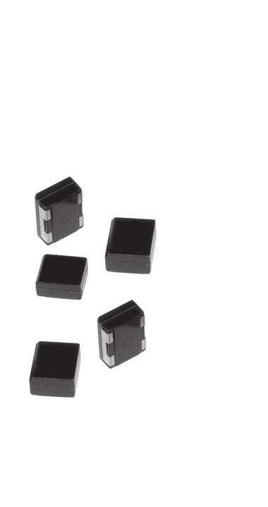
75 TANTALUM CAPACITORS SOLID TANTALUM POLYMER CAPACITORS
76 SOLID TANTALUM POLYMER CAPACITORS MOLDED CASES - SMD General Information OVERVIEW The construction of solid tantalum polymer capacitors is similar to the one of solid tantalum MnO 2 capacitors: the anode is made of tantalum and its oxide constitutes the dielectric, the cathode is made of a conductive polymer to replace MnO 2. CONSTRUCTION Chamfer = Polarity + Tantalum - lead frame welding Silver epoxy bonding Negative lead Positive lead Epoxy resin Tantalum pentoxide Conductive polymer Silver Tantalum powder Graphite Benefits of conductive polymer used as a cathode are a better conductivity and a higher retention frequency which enable to reach a very low ESR. The second advantage of conductive polymer as compare to manganese oxide is a self-healing mechanism which is less exothermic avoiding ignition failures. RECOMMENDED MOUNTING PAD GEOMETRY Vapor phase or infrared soldering (in mm) D B C E A F MARKING + FIRCA + F + V + Positive mark Capacitance in µf Voltage in V Date code = Year : 2 digits Week : 2 digits A Dimensions (mm) Case code A min. B nom. C nom. D nom. E nom. F nom. D 3,6 3,3 7,6 14,2 1,35 3,8 76
77 MOLDED CASES - SMD SOLID TANTALUM POLYMER CAPACITORS General Information CAPACITANCE CHANGE VS FREQUENCY (TYPICAL) ESR CHANGE VS FREQUENCY (TYPICAL) Capacitance 1000 ESR Capacitance in µf CTP21 560µF/16 V ESR in mω 10 CTP21 560µF/16 V 0 0,01 0, Frequency in khz 1 0,01 0, Frequency in khz CAPACITANCE CHANGE VS FREQUENCY (TYPICAL) ESR CHANGE VS FREQUENCY (TYPICAL) Capacitance ESR Capacitance in µf CTP21 330µF/25 V ESR in mω CTP21 330µF/25 V 0 0,01 0, Frequency in khz 1 0,01 0, Frequency in khz CAPACITANCE CHANGE VS FREQUENCY (TYPICAL) ESR CHANGE VS FREQUENCY (TYPICAL) Capacitance 1000 ESR Capacitance in µf ESR in mω CTP21 150µF/40 V 0 0,01 0, Frequency in khz CTP21 150µF/40 V 10 0,01 0, Frequency in khz 77
78 SOLID TANTALUM POLYMER CAPACITORS General Information MOLDED CASES - SMD CAPACITANCE CHANGE VS FREQUENCY (TYPICAL) ESR CHANGE VS FREQUENCY (TYPICAL) 60 Capacitance ESR Capacitance in µf ESR in mω CTP21 56µF/63V CTP21 56µF/63 V 0 0,01 0, Frequency in khz 10 0,01 0, Frequency in khz CAPACITANCE CHANGE VS FREQUENCY (TYPICAL) Capacitance in µf CTP21 47µF/75 V Capacitance 0 0,01 0, Frequency in khz ESR CHANGE VS FREQUENCY (TYPICAL) ESR in mω CTP21 47µF/75 V ESR 1 0,01 0, Frequency in khz 78
79 MOLDED CASES - SMD SOLID TANTALUM POLYMER CAPACITORS General Information CAPACITANCE CHANGE VS TEMPERATURE ESR CHANGE VS FREQUENCY 1,5 2,5 C/C 1,4 1,3 1,2 1,1 1 0,9 Maximum Minimum ESR/ESR 2 1,5 1 0,8 0,5 0,7 0, Temperature ( C) Frequency (khz) 79

80 SOLID TANTALUM POLYMER CAPACITORS MOLDED CASES - SMD CTP21 Polymer tantalum capacitors Very low ESR SMD Polarized ELECTRICAL AND CLIMATIC CHARACTERISTICS CTP21 Operating temperature +105 C Damp heat 56 days Capacitance range 47µF 560µF Tolerance ±10% - ±20% Voltage range 16V 75V Max. capacitance change 25% Max. capacitance change +15% Max. capacitance change +105 C +25% Maximum DF at Maximum DF at Maximum DF at 1,2 x lim. 20 C Maximum DF at +105 C 1,2 x lim. 20 C Max. leakage current at Max. leakage current at 10 x lim. 20 C Max. leakage current at +105 C 10 x lim. 20 C / U C Max. ESR at 100kHz DIMENSIONS (mm) Dimensions Case code L + 0,5 0,1 W + 0,1 0,5 H + 0,5 0,1 T 0,1 W + 0,5 P T D 11 12,5 5,5 10,5 1,5 3 H L W P Tw MARKING, PACKAGING, CONSTRUCTION: see general characteristics W T HOW TO ORDER Commercial description EXXELIA PN Model Case Capacitance in µf Tolerance in % DC Voltage Termination Packaging CTP21 D 150µF 20% 40V T R Model code Case Capacitance code Tolerance code DC Voltage code Termination Packaging CTP21 D 157 M 040 T R Expressed in pf with 3 digits: 2 digits for the value and T = SnPb (non RoHS) Commercial description / EXXELIA PN K = 10% Expressed in volt - = Bulk M = 20% with 3 digits R = Tape & Reel the third for the multiplier F = Sn100% (RoHS) 80
81 MOLDED CASES - SMD SOLID TANTALUM POLYMER CAPACITORS CTP21 STANDARD RATINGS - ELECTRICAL CHARACTERISTICS Capacitance 100Hz (µf) Case (code) Type Max. I leak +105 C Max. DF 100Hz Max. DF 100Hz Max. DF 100Hz Max. DF 100Hz +105 C Max. ESR 100kHz (mω) Rated voltage () 16 V - Category voltage (+105 C) 12 V 390 D CTP21 62, ,2 19,2 30 3,4 470 D CTP21 75, ,2 19,2 30 3,5 560 D CTP21 89, ,2 19,2 30 3,7 Rated voltage () 25 V - Category voltage (+105 C) 20 V 180 D CTP ,4 14,4 40 2,5 270 D CTP21 67, ,4 14,4 35 2,7 330 D CTP21 82, ,4 14,4 35 2,9 Rated voltage () 40 V - Category voltage (+105 C) 30 V 68 D CTP21 27, ,4 82 D CTP21 32, ,5 100 D CTP ,6 120 D CTP ,7 150 D CTP21 60, ,8 Rated voltage () 50 V - Category voltage (+105 C) 40 V 68 D CTP21 34, ,3 Rated voltage () 63 V - Category voltage (+105 C) 50 V 33 D CTP21 29, ,7 47 D CTP21 29, ,9 56 D CTP21 35, ,1 Rated voltage () 75 V - Category voltage (+105 C) 60 V 33 D CTP21 24, ,8 47 D CTP21 35, ,9 Irms Max. 100kHz (A) STANDARD TERMINATIONS: T F tinning electrolytic SnPb (non RoHS) tinning electrolytic 100% Sn (RoHS) PACKAGING: Standard: Bulk Optional: Tape & Reel When ordering add the suffix «R» just after the termination code. 81

 Case code Dimensions (mm) L 1 + 0.5 W 1 + 0.5 H 1 + 0.5 Tw 1 + 0.")
82 SOLID TANTALUM POLYMER CAPACITORS MOLDED CASES - SMD CTP42 Polymer tantalum capacitors Ultra low ESR High capacitance SMD Polarized ELECTRICAL AND CLIMATIC CHARACTERISTICS CTP42 Operating temperature +105 C Damp heat 56 days Capacitance range 68µF 1200µF Tolerance ±10% - ±20% Voltage range 16V 75V Max. capacitance change 25% Max. capacitance change +15% Max. capacitance change +105 C +25% Maximum DF at Maximum DF at Maximum DF at 1,2 x lim. 20 C Maximum DF at +105 C 1,2 x lim. 20 C Max. leakage current at Max. leakage current at 10 x lim. 20 C Max. leakage current at +105 C 10 x lim. 20 C / U C Max. ESR at 100kHz DIMENSIONS (mm) Case code Dimensions (mm) L W H Tw P T D 12 12,5 11,5 10,5 1,5 3 MARKING, PACKAGING, CONSTRUCTION: see general characteristics HOW TO ORDER Commercial description EXXELIA PN Model Case Capacitance in µf Tolerance in % DC Voltage Termination CTP42 D 150µF 20% 50V T Model code Case Capacitance code Tolerance code DC Voltage code Termination CTP42 D 157 M 050 T Expressed in pf with 3 digits: 2 Commercial description / EXXELIA PN K = 10% Expressed in volt digits for the value and the third for the T = SnPb (non RoHS) M = 20% with 3 digits multiplier F = Sn100% (RoHS) 82
83 MOLDED CASES - SMD SOLID TANTALUM POLYMER CAPACITORS CTP42 STANDARD RATINGS - ELECTRICAL CHARACTERISTICS Capacitance 100Hz (µf) Case (code) Type Max. Leakage Current +105 C 100Hz Max. Dissipation Factor 100Hz 100Hz 100Hz +105 C Max. ESR 100kHz (mω) Rated voltage () 16 V - Category voltage (+105 C) 12V 1000 D CTP D CTP Rated voltage () 25 V - Category voltage (+105 C) 20 V 540 D CTP D CTP Rated voltage () 40V - Category voltage (+105 C) 30 V 220 D CTP D CTP Rated voltage () 50V - Category voltage (+105 C) 40 V 150 D CTP Rated voltage () 63V - Category voltage (+105 C) 50 V 100 D CTP D CTP Rated voltage () 75V - Category voltage (+105 C) 60 V 68 D CTP D CTP Irms Max. 100kHz (A) STANDARD TERMINATIONS: T F tinning electrolytic SnPb (non RoHS) tinning electrolytic 100% Sn (RoHS) PACKAGING: Standard: Bulk 83
84 SOLID TANTALUM POLYMER CAPACITORS MOLDED CASES - SMD Tape & Reel packaging (only CTP21) As per IEC TAPE DIMENSIONS (mm) P 0 D 0 P 2 «T» «L» F E W ± 0,3 E ± 0,1 F ± 0,05 P 0 ± 0,1 D 0 + 0,1 0 D 1 ± 0,1 G min. P 1 ± 0,1 P 2 ± 0,05 24,0 1,75 11,5 4,0 1,5 1,5 0,75 16,0 2,0 Cover tape K 0 A 0 B 0 +FIRCA + +C +FIRCA + +D D 1 P 1 G W Note: A 0 B 0 K 0 are defined by component size Reel diameter: 330 mm (nominal) Diameter of central hole: 12,8 mm Direction of unreeling REEL CHARACTERISTICS Case (code) Tape width (mm) Quantity per Reel (mm) Position D 24,0 400 L 16,0 Pitch Note: The minimum quantity per reel is 50% of the above mentioned one COMPONENT POSITION T = Transversal (+ termination away from the sprocket hole) L = Longitudinal (+ termination in the direction of unreeling) 84


85 TANTALUM CAPACITORS SOLID TANTALUM MnO 2 CAPACITORS
86 SOLID TANTALUM MnO 2 CAPACITORS Electrical characteristics HERMETICALLY SEALED - METAL CASES CAPACITANCE The capacitance is defined by a rated value (C R, indicated on the capacitor) and a tolerance (generally ±20%). The capacitance is measured for most of the types at a 100Hz frequency (1 khz for CTS21 - CTS21E - CTC21 - CTC21E) under a 0,1 to 1 V AC voltage and a 2,1 to 2,5 V bias. At room temperature, it must be in the range defined by the rated value and the tolerance. Capacitance change vs applied DC voltage: negligeable CAPACITANCE CHANGE VS FREQUENCY: STANDARD TYPES C/C 100% 50% CAPACITANCE CHANGE VS TEMPERATURE: CTC21 AND CTS21 C/C +15% +10% +5% 0 5% 10% T ( C) See typical curves below. Maximum changes are given, for each type, on the data sheets. TOLERANCE (ON RATED CAPACITANCE) It defines, with the rated capacitance, the range in which the capacitance value must be at room temperature e.g.: Rated capacitance: 100µF Tolerance: 20% The measured capacitance must be between: (20% of 100) = 80 and (20% of 100) = 120 The standard tolerance for tantalum capacitors is 20%. ±20% ± 20% ±20% ±20% ±20% ±20% 100 1k 10k 100k f (Hz) CAPACITANCE CHANGE VS TEMPERATURE: STANDARD TYPES C/C +15% +10% +5% DIRECT DC VOLTAGE The rated voltage (U R ), indicated on the capacitor, is the maximum DC voltage which can be applied continuously between and. For the types which can be used up to 125 C, the voltage must be derated between and according to the following curve. 0 5% U R 10% T ( C) CAPACITANCE CHANGE VS FREQUENCY: CTC21 AND CTS U C = 66% U R C/C 100% % T ( C) The category voltage (U C ) is consequently the maximum DC voltage which can be applied continuously at. The surge voltage is the maximum voltage which can be applied for short periods. It is given for each type in the data sheet and is generally equal to 1,3 times U R between and and 1,3 times U C at. Tests are performed with charging periods of 30 seconds, through a 1000 Ω resistor, and discharging periods of 5 min 30 s cycles are done. 1k 10k 100k 1M f (Hz) 86
87 HERMETICALLY SEALED - METAL CASES SOLID TANTALUM MnO 2 CAPACITORS Electrical characteristics REVERSE VOLTAGE This characteristic is not guaranteed for all types (see data sheets). MAXIMUM REVERSE VOLTAGE IS GENERALLY: 0,15 times U R at 0,05 times U R at 0,01 times U R at TESTS ARE PERFORMED WITH THE FOLLOWING CONDITIONS: 125 hours under Reverse voltage followed by 125 hours under direct voltage. LEAKAGE CURRENT Leakage current is the residual current which flows through the capacitor after the charging time, under rated voltage. It is measured after a time not exceeding 5 minutes and is given in µa. It is equivalent to the insulation resistance of the capacitor and it must be as low as possible. Maximum leakage current is a function of capacitance and rated voltage values and is given, for each type, in the data sheets. AT 20 C, THE LIMIT IS GENERALLY: Lc Max. = 0,01 x C R x U R with C R in µf and U R in V. LEAKAGE CURRENT CHANGE VS APPLIED VOLTAGE DISSIPATION FACTOR Dissipation factor is generally measured at the same time as the capacitance (at 100Hz or 1kHz depending on the model), with the same conditions. It is a function of the series resistance of the capacitor and the capacitance at low frequency. DF = ESR x C x 2p f At low frequency, the series resistance is the sum of an ohmic part (leads, contacts, MnO 2 ) and the dielectric losses. Dissipation factor is given in % and maximum limits are given for each type in the data sheets. DISSIPATION FACTOR CHANGE VS TEMPERATURE DF (10 2 ) Dissipation factor Temperature ( C) DISSIPATION FACTOR CHANGE VS FREQUENCY Multiplier of leakage current LEAKAGE CURRENT CHANGE VS TEMPERATURE Multiplier of leakage current % U R - Percentage of rated voltage Multiplier of 100Hz dissipation factor DF (f) Tg δ (100Hz) k 10k Frequency (Hz) Lc (t C) Lc () Temperature ( C) 87
88 SOLID TANTALUM MnO 2 CAPACITORS Electrical characteristics HERMETICALLY SEALED - METAL CASES EQUIVALENT SERIES RESISTANCE OR IMPEDANCE Equivalent circuit of a capacitor R C L R Z 1/ Cω R: equivalent series resistance of the capacitor (leads,contacts, MnO 2, dielectric losses) L: inductance mainly due to the leads C: capacitance Equivalent Series Resistance for CTS21 CTC21 CTC4 CTS41ESR CTC42 CTP21 CTS21E CTC21E CTC4 RSE CTC42E CTP42 For these types which are specially designed to be used in power supplies and converters, a maximum ESR is given at a frequency of 100kHz or 500 khz. Parameters such output ripple voltage and ripple current capability are directly a function of the ESR value. Maximum ESR: see data sheets. Impedance (for standard products) For the others types, a maximum limit is given for the impedance. The formula for impedance is: Z = BR 2 + (Lq - 1/Cq) 2 Examples of impedance curves vs frequency are given in the following pages. It can be seen that: at low frequencies, impedance is a function of capacitance at high frequencies, impedance is a function of inductance at medium frequencies, it is a function of the ESR Maximum impedance: see data sheets. Lω ESR CHANGE VS TEMPERATURE ESR T ( C) ESR CHANGE VS FREQUENCY ESR k 10k 100k 1M f (Hz) 88
89 HERMETICALLY SEALED - METAL CASES SOLID TANTALUM MnO 2 CAPACITORS Electrical characteristics CTS1 TYPE Impedance (Ohms) CTS1 Type µf - 10 V (A) µf - 16 V (B) µf - 10 V (C) µf V (D) CTS27 TYPE Impedance (Ohms) CTS27 Type 1. 1 µf - 40 V (A) µf - 25 V (B) µf - 16 V (C) µf - 16 V (D) k 10k 100k 1M 10M k 10k 100k 1M 10M CTS4 TYPE Impedance (Ohms) CTS4 Type 1. 1 µf - 20 V (B) 2. 4,7 µf - 20 V (C) µf - 6,3 V (E) µf - 10 V (F) Frequency (Hz) CTC3 TYPE Impedance (Ohms) CTC3 Type 1. 1 µf - 35 V (A) µf - 16 V (B) µf - 16 V (C) µf - 10 V (D) Frequency (Hz) k 10k 100k 1M 10M Frequency (Hz) CTS21 TYPE CASE C Impedance (Ohms) 1000 CTS21 Type Case C µf - 50 V µf - 20 V µf - 10 V k 10k 100k 1M 10M Frequency (Hz) CTS21 TYPE CASE D Impedance (Ohms) 1000 CTS21 Type Case D µf - 50 V µf - 40 V µf - 20 V µf - 10 V k 10k 100k 1M 10M Frequency (Hz) k 10k 100k 1M 10M Frequency (Hz ) 89
90 SOLID TANTALUM MnO 2 CAPACITORS HERMETICALLY SEALED - METAL CASES Electrical characteristics CTS21E TYPE CASE C CTS21E TYPE CASE D Impedance (Ohms) Impedance (Ohms) CTS21E Type Case C CTS21E Type Case D µf - 50 V µf - 40 V µf - 20 V µf - 10 V µf - 50 V µf - 40 V µf - 20 V µf - 10 V k 10k 100k 1M 10M Frequency (Hz) k 10k 100k 1M 10M Frequency (Hz) CTC21 TYPE CASE C Impedance (Ohms) 1000 CTC21 Type Case C CTC21 TYPE CASE D Impedance (Ohms) 1000 CTC21 Type Case D µf - 63 V µf - 40 V µf - 16 V µf V µf - 63 V µf - 40 V µf - 10 V k 10k 100k 1M 10M Frequency (Hz) k 10k 100k 1M 10M Frequency (Hz) CTC21E TYPE CASE C CTC21E TYPE CASE D Impedance (Ohms) Impedance (Ohms) CTC21E Type Case C CTC21E Type Case D µf V µf - 40 V µf - 25 V µf V µf V µf - 40 V µf - 20 V µf V k 10k 100k 1M 10M Frequency (Hz) k 10k 100k 1M 10M Frequency (Hz) 90
91 HERMETICALLY SEALED - METAL CASES SOLID TANTALUM MnO 2 CAPACITORS Electrical characteristics MAXIMUM RIPPLE CURRENT - MAXIMUM RIPPLE VOLTAGE The maximum value of the ripple current, or ripple voltage which can be applied to the capacitor is only limited by the thermal effect. Indeed, as the electrolyte is in this case a solid semi-conductor, there is no damage and physical change in the structure when a ripple current is flowing through it. On the other hand, as the series resistance is not zero, there will be a heating which is proportional to the ESR and to the square of ripple current (P = ESR x Irms 2 ) Types CTS21 CTC21 CTC4 CTS41 RSE CTC42 SMT47 CTS21E CTC21E CTC4 RSE CTC42E For these products, for which a maximum ESR is given, the maximum ripple current is also given in the data sheets. This value has been calculated with the maximum ESR values and a maximum dissipated power per case size. As there is heating due to the ripple current, it is also necessary to derate the maximum ripple current when the room temperature is higher than 20 C: C 25 C 45 C 65 C 85 C 105 C 125 C T ( C) TYPICAL HEATING OF THE CASE VS DISIPATED POWER As the ESR changes in frequency, maximum ripple currents are given for two frequencies (1kHz and 100kHz). For other frequencies, apply the rule given by the curve below. COEFFICIENT APPLY TO THE MAXIMUM RIPPLE CURRENT VS TEMPERATURE T case 60 C 50 C CTC21 Case C l rms max. (A) 40 C 30 C CTC21 Case D l rms max. at 100 khz 20 C 10 C l rms max. at 1 khz 500 mw 1W 1,5W 0.1k 1k 10k 100k 1M Frequency (Hz) 91
92 SOLID TANTALUM MnO 2 CAPACITORS HERMETICALLY SEALED - METAL CASES Electrical characteristics OTHERS TYPES The same rule will be used to calculate the maximum ripple voltage: Irms Max. = B(Pmax/ESR max) MAXIMUM DISSIPATED POWER WILL BE CHOSEN AS FOLLOW: Metal cases (CTS1, CTS13, CTS23, CTS33,... ) case A : 0,090 W case C : 0,125 W case B : 0,100 W case D : 0,180 W Plastic cases (CTS27) case A : 0,080 W case B : 0,090 W case C : 0,100 W case D : 0,125 W SMD cases (CTC3, CTC3E,... ) case A : 0,075 W case S : 0,060 W case B : 0,085 W case T : 0,070 W case C : 0,110 W case U : 0,090 W case D : 0,150 W case V : 0,0125 W These values should be derated at elevated temperature as follows at : 0,9 at: 0,4 For maximum values of ESR, it will be possible to use the maximum impedance value given at 100kHz or to measure the ESR of capacitors. Maximum ripple voltage can be calculated with the value of maximum ripple current and the following formula Urms = Z (impedance) x Irms NOTE FOR ALL TYPES In addition to the requirements due to thermal effects, maximum ripple currents and voltages will be limited by the following parameters: the sum of DC voltage and positive peak of AC voltage must be less than maximum allowable direct voltage of the capacitor. the negative peak of AC voltage will not create a voltage exceeding maximum allowable Reverse voltage. 9 - CHARGE DISCHARGE / SURGE CURRENT For standard types of solid tantalum capacitors, it is necessary to limit the surge current by placing a resistance in series with the capacitor. The value of this resistance will be calculated by using the rule of 3Ω per volt (IMax. = 0,33 A). However, some more recent types can be used without any limit on the surge current; these types are registered with the reference «high surge current» (eg : CTS32, CTS23, CTS33, CTS21, CTS21E, CTS41, CTS41ESR, CTC4, CTC4 RSE, CTC21, CTC21E, CTC42, CTC42E, SMT47). Circuit resistance < 0,5Ω Electronic or mechanical switch U R 0,5s 0,5 s t Power supply I Energy storage bank capacitor ( µf ) Circuit resistance < 0,5Ω Capacitor under test t The high surge current test is performed to check that these capacitors can be used in low impedance circuits, and to make sure of their capability to withstand high surge currents. The test being performed under rated voltage with a maximum 0,5 Ω circuit resistance, the peak surge current will be a minimum equal to Ip = U R / 0,5 (if the ESR of the capacitor is considered as negligible). e.g.: high surge current test performed on a CTS21 100µF-20 V (ESR=75mΩ, negligible compared to 0,5Ω) Surge current = 20/0.5 = 40 A during a few tens of µs. Depending upon the types, this test can be 100% performed or on a sampling basis, during 3 to 5 cycles. During periodic tests, 1 million cycles are performed. 92
93 HERMETICALLY SEALED - METAL CASES SOLID TANTALUM MnO 2 CAPACITORS General characteristics CLIMACTIC CHARACTERISTICS 1- CLIMATIC CATEGORY Climatic category defines the temperature range over which the capacitor can be used continuously, and also the number of days for the damp heat test (this test is performed periodically at 40 C with a 93% moisture rate). Note: for types with a climatic range of to, it is necessary to derate the voltage for temperatures higher than 85 C (see page 84). 2- THERMAL SHOCKS - RAPID CHANGES OF TEMPERATURE This test is performed to check that the capacitors can withstand sudden temperature changes. The method which is used is the one with two chambers, one at, the other one at or, depending upon the types. Five cycles are performed, with 30 min at low temperature and 30 min at high temperature, during the periodic tests or on 100% of the batch. Electrical characteristics are measured after this test. 3 - DAMP HEAT TEST This test is performed during the periodical test, with the following conditions: Temperature: 40 C DC voltage: without Humidity: 90 to 95% Time: 21 or 56 days Electrical characteristics are measured after this test. MECHANICAL CHARACTERISTICS 1 - VIBRATIONS This test is performed during the periodical test, with the following conditions: Metal cases Method B4 Amplitude: 1,5 mm or 196 m/s 2 Frequency: 10 to 2000Hz Time: 6 hours Plastic cases: CTS4 or CTS41 Type Same conditions, except: Amplitude 0,75 mm or 98 m/s 2 Plastic cases: CTS27 Type Same conditions, except: Frequency: 10 to 55Hz Amplitude: 1,5 mm or 98 m/s SHOCKS This test is performed just after the vibrations test, with the following conditions for all types: Acceleration: 981 m/s 2 Shape: 1/2 sinewave Pulse width: 6 ms Number of shocks: 3 for each of the 3 directions RELIABILITY - LIFE TIME 1 - RELIABILITY Reliability of a component can be defined as its probability to work without any failure, in defined conditions and during a fixed time. Reliability is not therefore only a function of the component quality, but also of the application and environmental conditions. The parameter which is the most commonly used for the reliability is the failure rate in time, generally expressed in % per 1000 hours. 1-1 ESTABLISHED FAILURE RATE CAPACITORS (CTS1M) This types, equivalent to MIL types, can be supplied with a fixed failure rate. This failure rate is coded with the following letters: M = 1.0 % / 1000 h P = B = 0.1% / 1000 h R = C = 0.01% / 1000 h S = D = 0.001% / 1000 h For EXXELIA, the rate is calculated by recording the failures during the burn-in and according to the Weibull method. The desired failure rate code letter must be added just after the type reference (ie: CTS1MC = CTS1M with a failure rate of 0.01% / 1000 hours). 1-2 CALCULATION OF A COMPONENT FAILURE RATE USED IN AN EQUIPMENT The calculation method on the next page uses parameters which are given by the CNET (Centre National d Étude des Télécommunications) in its Reliability Data Book (RDF 1993). The failure rate is calculated with parameters which are function of the capacitor (capacitance, case type, approvals, high surge current test) and others ones which are representative of application conditions (voltage, temperature, resistance in series, environmental conditions). Example: CTS21E 150µF-25 V used under 12 volts, at 40 C, without serie resistance, in a satellite in orbit: p t = 1,2 p V = 1,38 p R = 1 p B = 1 p C = 1,8 p E = 0,5 p q = 1 l = 4 x 1,2 x 1,38 x 1 x 1 x 1,8 x 0,5 x /h = /h = 0,0006 % defect/1000 hours 2 - LIFE TIME There is no known damaging mechanism in time for solid tantalum capacitors; that is why it is difficult to give a precise life time. However, life tests at 85 C under rated voltage and 125 C under derated voltage are periodically performed. In addition, during qualification programs for new types, life test at 85 C and 125 C have been performed during hours and no significant parameter change have been observed. 93
94 SOLID TANTALUM MnO 2 CAPACITORS General characteristics HERMETICALLY SEALED - METAL CASES p t = TEMPERATURE INFLUENCE t Formula: p t = exp (1,8.( t / tm) 2 ) with: t = using temperature tm = maximum temperature Curve for tm = 125 C p V = INFLUENCE OF APPLIED VOLTAGE VS RATED VOLTAGE V Formula: p v = exp (( r / 0,85) 2 ) peak voltage r = rated voltage T ( C) p R = INFLUENCE OF CIRCUIT RESISTOR IN SERIE V = using voltage R = circuit resistance between capacitor and power supply 1. Types with high surge current test: p R = 1 2. Others types: p R = function of R/V in /V R/V 3 R = 1 R/V = 0,6 R = 6 R/V = 2 R = 1,5 R/V = 0,4 R = 9 R/V = 1 R = 3 R/V = 0,2 R = 12 R/V = 0,8 p R = 4,5 R/V = 0,1 p R = 15 p E = INFLUENCE OF APPLICATION Satellite in orbit E = 0,5 Ground; stationary; protected E = 1 Ground; stationary; non protected E = 2,5 Ground; mobile; soft conditions E = 4 Aircraft; soft conditions E = 4 Ship; soft conditions E = 4 Ground; mobile; hard conditions E = 5,5 Ship; hard conditions E = 7 Aircraft; hard conditions E = 10 Satellite launching p E = 12 p B = INFLUENCE OF CASE TYPE Metal case B = 1 Molded case B = 3 Dipped p B = 5 p C = INFLUENCE OF CAPACITANCE 0,1µF C = 0,75 150µF C = 1,8 330µF C = µF p C = 3 p q = INFLUENCE OF QUALIFICATION Products approved to CECC q = 1 Others products p q = 1 Curve p v = f (r) 94
95 HERMETICALLY SEALED - METAL CASES SOLID TANTALUM MnO 2 CAPACITORS Axial leads - General characteristics Applicable for types see below: General purpose: CTS1, CTS13, CTS32, CTS1M Extended ranges: CTS23, CTS33 Special for power supplies and converters: CTS21, CTS21E CONSTRUCTION Soldering Glass metal seal Soldering Metal case Soldering Nickel lead (positive) Nickel-Tantalum welding Tantalum pentoxide Tantalum powder Nickel lead (negative) Manganous dioxide Graphite Silver MARKING FIRCA CTS + + V µf % Brand Type Capacitance Voltage Tolerance (except 20%) Date code = year : 2 digits week : 2 digits PACKAGING Depending upon the quantities, there will be different types for packaging: Loose in plastic bags or boxes Taped in plastic bags Taped on reel Dimensions about taping and reels are given on the next page. 95
96 SOLID TANTALUM MnO 2 CAPACITORS Axial leads - Tape & Reel Packaging HERMETICALLY SEALED - METAL CASES LENGTH OF THE CAPACITOR (+) White S ( ) Color 1.2 TAPE DIMENSIONS (in mm) Case code L max. K max. * b ± 2 C max. ** S ± 0,5 Qty per ree Std/max. A 8,1 9, B 12,8 14, C 18,2 18, D 20,8 20, * The size b of 53 mm for B case is the standard dimension. ** Max. cumulative tolerance on 10 capacitors: ±2 mm 6 ± 1 L* 6 ± 1 K b C REEL SIZE (in mm) Ø 16 ± 1 or 27 ± 1 (-) 3 ± 0,5 Size E of reels according to case sizes. EA = 67 B = 67 C-D = 87 Ø 81 Ø 268 ± 2 or 300 ± 2 E 96

97 HERMETICALLY SEALED - METAL CASES SOLID TANTALUM MnO 2 CAPACITORS CTS1 - CTS13 CTS32 - CTS1M Solid tantalum MnO 2 capacitors Hermetically sealed metal cases Axial leads General purpose - Standard range Polarized ELECTRICAL AND CLIMATIC CHARACTERISTICS CTS1 CTS13 CTS32 CTS1M Detail specification CECC CECC CECC Ac cording to MIL-PRF-39003/01 CECC CECC Operating temperature Damp heat 56 days 56 days 56 days 56 days Capacitance range 0,1µF 330µF 0,1µF 330µF 1µF 330µF 0,1µF 330µF Tolerance ±10% - ±20% ±10% - ±20% ±10% - ±20% ±10% - ±20% Voltage range 6,3V 125V 6,3V 63V 6,3V 63V 6,3V 100V Max. capacitance change 10% 10% 10% 10% Max. capacitance change +12% +12% +12% +8% Max. capacitance change +15% - +15% +12% Maximum DF at Maximum DF at 1,5 x lim20 C 1,5 x lim20 C 1,5 x lim20 C = lim20 C Maximum DF at 1,5 x lim20 C 1,5 x lim20 C 1,5 x lim20 C = lim20 C Maximum DF at 2,0 x lim20 C 2,0 x lim20 C = lim20 C Max. leakage current at Max. leakage current at 0,1 x C R U R 0,1 x C R U R 0,1 x C R U R 20 x lim 20 C Max. leakage current at 0,125 x C R U R - 0,125 x C R U R 25 x lim 20 C Max. impedance (20 C): case A 10 Ω 10 Ω 10 Ω 10 Ω Max. impedance (20 C): case B 5 Ω 5 Ω 5 Ω 5 Ω Max. impedance (20 C): case C 2 Ω 2 Ω 2 Ω 2 Ω Max. impedance (20 C): case D 1 Ω 1 Ω 1 Ω 1 Ω High surge current no no 1 million cycles 3 cycles-100% Max. Reverse voltage at % U R 15 % U R Max. Reverse voltage at % U R 5 % U R Max. Reverse voltage at % U R 1 % U R Max. surge voltage at 1,3 x U R 1,3 x U R 1,3 x U R 1,3 x U R Max. surge voltage at 1,3 x U C - 1,3 x U C 1,3 x U C DIMENSIONS (mm) Case code Dimensions with insulating sleeve Lt max L max D max d +10%/ 0,05 A 10,2 8,1 3,6 0,5 B 15,0 12,8 4,9 0,5 C 20,5 18,2 7,5 0,6 D 24,0 20,8 9,1 0,6 MARKING, PACKAGING, CONSTRUCTION: see general characteristics 30 min (*) L 30 min (*) d D Lt (*) 23mm for capacitors delivered on tape HOW TO ORDER Commercial description EXXELIA PN Model Case Capacitance in µf Tolerance in % DC Voltage Termination CTS1 CTS13 CTS32 CTS1M D 150µF 20% 16V H Model code Case Capacitance code Tolerance code DC Voltage code Termination TS01 TS13 TS32 TS01M D 157 M 016 A Expressed in pf with 3 digits: Commercial description EXXELIA PN K = 10% Expressed in volt 2 digits for the value H = SnPb (non RoHS) A = SnPb (non RoHS) M = 20% with 3 digits and the third for the multiplier - = Sn100% (RoHS) F = Sn100% (RoHS) 97
98 SOLID TANTALUM MnO 2 CAPACITORS CTS1 - CTS13 CTS32 - CTS1M HERMETICALLY SEALED - METAL CASES STANDARD RATINGS - ELECTRICAL CHARACTERISTICS Capacitance 100Hz (µf) Case (code) Type Max. leakage current Max. DF Type Max. leakage current Rated voltage () 6,3 V (6 V for CTS1M) - Category voltage () 4 V 5,6 A CTS1 CTS13 CTS32 1 3,5 4,4 6 CTS1M 0,3 6 7,5 4 6,8 A CTS1 CTS13 CTS32 1 4,2 5,3 6 CTS1M 0,3 6 7, B CTS1 CTS13 CTS32 2, CTS1M 1, B CTS1 CTS13 CTS32 3, CTS1M 1, C CTS32 7, C CTS1 CTS13 CTS32 9, CTS1M 4, C CTS1 CTS13 CTS32 11, CTS1M 5, D CTS1 CTS13 CTS CTS1M 6, D CTS1 CTS13 CTS32 20, CTS1M 7, Rated voltage () 10 V - Category voltage () 6,3 V 3,9 A CTS1 CTS13 CTS32 1 3,9 4,8 6 CTS1M 0,3 6 7,5 4 4,7 A CTS1 CTS13 CTS32 1 4,7 5,8 6 CTS1M 0,4 7 8, B CTS1 CTS13 CTS32 2, CTS1M B CTS1 CTS13 CTS32 3, CTS1M 2, B CTS1 CTS13 CTS32 3, CTS1M 2, C CTS1 CTS13 CTS32 8, CTS1M C CTS1 CTS13 CTS CTS1M C CTS1 CTS CTS1M D CTS1 CTS13 CTS CTS1M D CTS1 CTS13 CTS CTS1M Rated voltage () 16 V (15 V for CTS1M) - Category voltage () 10 V 1,8 A CTS1 CTS32 1 2,8 3,6 6 2,2 A CTS1 CTS32 1 3,5 4,4 6 2,7 A CTS1 CTS13 CTS32 1 4,3 5,4 6 CTS1M 0,3 6 7,5 4 3,3 A CTS1 CTS13 CTS32 1 5,2 6,6 6 CTS1M 0, B CTS1 CTS32 1, B CTS1 CTS32 2, B CTS1 CTS13 CTS32 2, CTS1M B CTS1 CTS13 CTS32 3, ,7 6 CTS1M C CTS1 CTS32 6, , C CTS1 CTS32 7, , C CTS1 CTS13 CTS32 8, CTS1M C CTS1 CTS13 CTS32 10, CTS1M D CTS1 CTS32 13, D CTS1 CTS D CTS1 CTS13 CTS32 19, CTS1M D CTS1 CTS13 CTS CTS1M Rated voltage () 20 V - Category voltage () 13 V 1,2 A CTS1M 0,3 6 7,5 4 1,5 A CTS1M 0,3 6 7,5 4 1,8 A CTS13 1 3,6 6 CTS1M 0,3 6 7,5 4 2,2 A CTS13 1 4,4 6 CTS1M 0, ,2 B CTS1M B CTS1M 1, B CTS13 2, CTS1M 1, B CTS CTS1M C CTS1M 2, C CTS1M 3, C CTS13 7, CTS1M C CTS13 9, CTS1M 4, D CTS1M 5, D CTS1M D CTS13 16, CTS1M D CTS CTS1M Rated voltage () 25 V - Category voltage () 16 V 1,2 A CTS ,7 6 1,5 A CTS1 CTS13 CTS32 1 3,7 4,6 6 8,2 B CTS1 CTS13 CTS B CTS1 CTS13 CTS32 2, , C Max. DF. +25 C 98
99 HERMETICALLY SEALED - METAL CASES SOLID TANTALUM MnO 2 CAPACITORS CTS1 - CTS13 CTS32 - CTS1M STANDARD RATINGS - ELECTRICAL CHARACTERISTICS Capacitance 100Hz (µf) Case (code) Type Max. leakage current Max. DF Type Max. leakage current Rated voltage () 25 V - Category voltage () 16 V 27 C CTS1 CTS13 CTS32 6, C CTS1 CTS13 CTS32 8, D CTS1 CTS13 CTS D CTS1 CTS13 CTS Rated voltage () 40 V (35 V for CTS1M) - Category voltage () 25 V (23 V for CTS1M) 0,1 A CTS1 CTS ,12 A CTS1 CTS ,15 A CTS1 CTS ,18 A CTS1 CTS ,22 A CTS1 CTS ,1 6 0,27 A CTS1 CTS ,3 6 0,33 A CTS1 CTS13 1 1,3 1,6 6 0,39 A CTS1 CTS13 1 1,5 1,9 6 0,47 A CTS1 CTS13 1 1,8 2,3 6 0,56 A CTS1 CTS13 1 2,2 2,8 6 0,68 A CTS1 CTS13 1 2,7 3,4 6 0,82 A CTS1 CTS13 1 3,2 4,1 6 1 A CTS1 CTS13 CTS ,2 B CTS1 CTS13 CTS32 1 4, ,5 B CTS1 CTS13 CTS ,5 6 1,8 B CTS1 CTS13 CTS32 1 7, ,2 B CTS1 CTS13 CTS32 1 8, ,7 B CTS1 CTS13 CTS ,5 6 3,3 B CTS1 CTS13 CTS32 1, ,2 6 3,9 B CTS1 CTS13 CTS32 1, ,7 6 4,7 B CTS1 CTS13 CTS32 1, ,5 6 5,6 B CTS1 CTS13 CTS32 2, ,5 6 CTS1M 1, ,8 B CTS1 CTS13 CTS32 2, ,7 6 CTS1M 1, ,2 C CTS1 CTS13 CTS32 3, C CTS1 CTS13 CTS C CTS1 CTS13 CTS32 4, C CTS1 CTS13 CTS C CTS1 CTS13 CTS32 7, C CTS1 CTS13 CTS32 8, CTS1M D CTS1 CTS13 CTS32 10, CTS1M 4, D CTS1 CTS13 CTS32 13, CTS1M 5, D CTS1 CTS13 CTS32 15, CTS1M D CTS1 CTS13 CTS32 18, CTS1M Rated voltage () 50 V - Category voltage () 32 V 0,1 A CTS1 CTS CTS1M 0,3 5 6,3 2 0,12 A CTS1 CTS CTS1M 0,3 5 6,3 2 0,15 A CTS1 CTS CTS1M 0,3 5 6,3 2 0,18 A CTS1 CTS ,1 6 CTS1M 0,3 5 6,3 2 0,22 A CTS1 CTS13 1 1,1 1,3 6 CTS1M 0,3 5 6,3 2 0,27 A CTS1 CTS13 1 1,3 1,6 6 CTS1M 0,3 5 6,3 2 0,33 A CTS1 CTS13 1 1,6 2 6 CTS1M 0,3 5 6,3 2 0,39 A CTS1 CTS13 1 1,9 2,4 6 CTS1M 0,3 5 6,3 2 0,47 A CTS1 CTS13 1 2,3 2,9 6 CTS1M 0,3 5 6,3 2 0,56 A CTS1 CTS13 1 2,8 3,5 6 CTS1M 0,3 5 6,3 2 0,68 A CTS1 CTS13 1 3,4 4,2 6 CTS1M 0,3 5 6,3 2 0,82 A CTS1 CTS13 1 4,1 5,1 6 CTS1M 0,3 5 6,3 2 1 A CTS1 CTS13 CTS ,2 6 CTS1M 0, ,2 B CTS1 CTS13 CTS ,5 6 CTS1M 0, ,5 B CTS1 CTS13 CTS32 1 7,5 9,3 6 CTS1M 0, ,8 B CTS1 CTS13 CTS ,2 6 CTS1M 0, ,2 B CTS1 CTS13 CTS32 1, ,7 6 CTS1M 0, ,7 B CTS1 CTS13 CTS32 1, ,2 6 CTS1M ,3 B CTS1 CTS13 CTS32 1, CTS1M 1, ,9 B CTS1 CTS13 CTS32 1, CTS1M 1, ,7 B CTS1 CTS13 CTS32 2, CTS1M 1, ,6 C CTS1 CTS13 CTS32 2, CTS1M 2, ,8 C CTS1 CTS13 CTS32 3, CTS1M 2, ,2 C CTS1 CTS13 CTS32 4, CTS1M 2, C CTS1 CTS13 CTS CTS1M 2, C Max. DF+25 C 99
100 SOLID TANTALUM MnO 2 CAPACITORS CTS1 - CTS13 CTS32 - CTS1M HERMETICALLY SEALED - METAL CASES STANDARD RATINGS - ELECTRICAL CHARACTERISTICS Capacitance 100Hz (µf) Case (code) Type Max. leakage current Max. DF Type Max. leakage current Rated voltage () 50 V - Category voltage () 32 V 12 C CTS1 CTS13 CTS CTS1M C CTS1 CTS13 CTS32 7, CTS1M C CTS1 CTS13 CTS CTS1M 4, D CTS1 CTS13 CTS CTS1M 5, Rated voltage () 63 V - Category voltage () 40 V 0,1 A CTS1 CTS ,12 A CTS1 CTS ,15 A CTS1 CTS ,1 6 0,18 A CTS1 CTS13 1 1,1 1,4 6 0,22 A CTS1 CTS13 1 1,3 1,7 6 0,27 A CTS1 CTS13 1 1,7 2,1 6 0,33 A CTS1 CTS ,5 6 0,39 A CTS1 CTS13 1 2, ,47 A CTS1 CTS13 1 2,9 3,7 6 0,56 A CTS1 CTS13 1 3,5 4,4 6 0,68 A CTS1 CTS13 1 4,2 5,3 6 0,82 B CTS1 CTS13 1 5,1 6,4 6 1 B CTS1 CTS13 CTS32 1 6,3 7,8 6 1,2 B CTS1 CTS13 CTS32 1 7,5 9,4 6 1,5 B CTS1 CTS13 CTS32 1 9,4 11,8 6 1,8 B CTS1 CTS13 CTS32 1, ,7 6 2,2 B CTS1 CTS13 CTS32 1, ,2 6 2,7 B CTS1 CTS13 CTS32 1, ,2 6 3,3 B CTS1 CTS13 CTS ,9 B CTS1 CTS13 CTS32 2, ,7 C CTS1 CTS13 CTS32 2, ,6 C CTS1 CTS13 CTS32 3, ,8 C CTS1 CTS13 CTS32 4, ,2 C CTS1 CTS13 CTS32 5, C CTS1 CTS13 CTS32 6, D CTS1 CTS13 CTS32 7, D CTS1 CTS13 CTS32 9, D CTS1 CTS13 CTS32 11, D CTS1 CTS13 CTS32 13, Rated voltage () 80 V (75 V for CTS1M) - Category voltage () 50 V 0,1 A CTS CTS1M 0,3 5 6,3 2 0,12 A CTS ,2 6 CTS1M 0,3 5 6,3 2 0,15 A CTS1 1 1,2 1,5 6 CTS1M 0,3 5 6,3 2 0,18 A CTS1 1 1,4 1,8 6 CTS1M 0,3 5 6,3 2 0,22 A CTS1 1 1,7 2,2 6 CTS1M 0,3 5 6,3 2 0,27 A CTS1 1 2,1 2,7 6 CTS1M 0,3 5 6,3 2 0,33 A CTS1 1 2,6 3,3 6 CTS1M 0,3 5 6,3 2 0,39 A CTS1 1 3,1 3,9 6 CTS1M 0,3 5 6,3 2 0,47 A CTS1 1 3,7 4,7 6 CTS1M 0,3 5 6,3 2 0,56 A CTS1 1 4,4 5,6 6 CTS1M 0,3 5 6,3 2 0,68 A CTS1 1 5,4 6,8 6 CTS1M 0,3 5 6,3 2 0,82 B CTS1 1 6,5 8,2 6 CTS1M 0,3 5 6,3 2 1 B CTS CTS1M 0,3 5 6,3 2 1,2 B CTS1 1 9, CTS1M 0,3 5 6,3 4 1,5 B CTS1 1, CTS1M 0, ,8 B CTS1 1, CTS1M 0, ,2 B CTS1 1, CTS1M 0, ,7 B CTS1 2, CTS1M ,3 B CTS1 2, CTS1M 1, ,9 B CTS1 3, CTS1M 1, ,7 C CTS1 3, CTS1M ,6 C CTS1 4, CTS1M ,8 C CTS1 5, CTS1M ,2 C CTS1 6, CTS1M C CTS CTS1M D CTS1 9, CTS1M D CTS CTS1M C Max. DF +25 C 100
101 HERMETICALLY SEALED - METAL CASES SOLID TANTALUM MnO 2 CAPACITORS CTS1 - CTS13 CTS32 - CTS1M STANDARD RATINGS - ELECTRICAL CHARACTERISTICS Capacitance 100Hz (µf) Case (code) Type Max. leakage current Max. DF Type Max. leakage current Rated voltage () 100 V - Category voltage () 63 V 0,1 A CTS ,2 6 CTS1M 0,3 5 6,3 2 0,12 A CTS1 1 1,2 1,5 6 CTS1M 0,3 5 6,3 2 0,15 A CTS1 1 1,5 1,8 6 CTS1M 0,3 5 6,3 2 0,18 A CTS1 1 1,8 2,2 6 CTS1M 0,3 5 6,3 2 0,22 A CTS1 1 2,2 2,7 6 CTS1M 0,3 5 6,3 2 0,27 A CTS1 1 2,7 3,3 6 CTS1M 0,3 5 6,3 2 0,33 A CTS1 1 3,3 4,1 6 CTS1M 0,3 5 6,3 2 0,39 A CTS1 1 3,9 4,8 6 CTS1M 0,3 5 6,3 2 0,47 A CTS1 1 4,7 5,8 6 CTS1M 0,3 5 6,3 2 0,56 A CTS1 1 5,6 7 6 CTS1M 0,3 5 6,3 2 0,68 B CTS1 1 6,8 8,5 6 CTS1M 0,3 5 6,3 2 0,82 B CTS1 1 8, CTS1M 0,4 5 6,3 2 1 B CTS CTS1M 0,5 5 6,3 2 1,2 B CTS1 1, CTS1M 0,5 5 6,3 4 1,5 B CTS1 1, CTS1M 0, ,8 B CTS1 1, CTS1M 0, ,2 B CTS1 2, CTS1M 0, ,7 B CTS1 2, CTS1M 1, ,3 C CTS1 3, CTS1M 1, ,9 C CTS1 3, CTS1M 1, ,7 C CTS1 4, CTS1M 2, ,6 C CTS1 5, CTS1M 2, ,8 C CTS1 6, CTS1M 2, ,2 D CTS1 8, D CTS Rated voltage () 125 V - Category voltage () 80 V 0,1 A CTS1 1 1,2 1,5 6 0,12 A CTS1 1 1,5 1,8 6 0,15 A CTS1 1 1,8 2,3 6 0,18 A CTS1 1 2,2 2,8 6 0,22 A CTS1 1 2,7 3,4 6 0,27 A CTS1 1 3,3 4,2 6 0,33 A CTS1 1 4,1 5,1 6 0,39 B CTS1 1 4, ,47 B CTS1 1 5,8 7,3 6 0,56 B CTS ,7 6 0,68 B CTS1 1 8, ,82 B CTS B CTS1 1, ,2 B CTS1 1, ,5 B CTS1 1, ,8 B CTS1 2, ,2 B CTS1 2, ,7 C CTS1 3, ,3 C CTS1 4, ,9 C CTS1 4, ,7 C CTS1 5, ,6 C CTS ,8 C CTS1 8, ,2 D CTS1 10, D CTS1 12, C Max. DF +25 C 101

102 SOLID TANTALUM MnO 2 CAPACITORS CTS23 CTS33 HERMETICALLY SEALED - METAL CASES Solid tantalum MnO 2 capacitors Hermetically sealed metal cases Axial leads General purpose - Extended range Polarized ELECTRICAL AND CLIMATIC CHARACTERISTICS CTS23 CTS33 Detail specification CECC qualified CECC qualified Operating temperature Damp heat 56 days 56 days Capacitance range 1µF 1200µF 1,2µF 1000µF Tolerance ±10% - ±20% ±10% - ±20% Voltage range 6,3V 63V 6,3V 50V Max. capacitance change 10% 10% Max. capacitance change +12% +8% Max. capacitance change +15% +12% Maximum DF at Maximum DF at = lim20 C = lim20 C Maximum DF at = lim20 C = lim20 C Maximum DF at = lim20 C = lim20 C Max. leakage current at Max. leakage current at 0,1 x C R U R 0,1 x C R U R Max. leakage current at 0,125 x C R U R 0,125 x C R U R Max. impedance (20 C): case A 10 Ω 10 Ω Max. impedance (20 C): case B 5 Ω 5 Ω Max. impedance (20 C): case C 2 Ω 2 Ω Max. impedance (20 C): case D 1 Ω 1 Ω High surge current 1 million cycles 1 million cycles Max. Reverse voltage at 15 % U R 15 % U R Max. Reverse voltage at 5 % U R 5 % U R Max. Reverse voltage at 1 % U R 1 % U R Max. surge voltage at 1,3 x U R 1,3 x U R Max. surge voltage at 1,3 x U C 1,3 x U C DIMENSIONS (mm) Case code Dimensions with insulating sleeve Lt max L max D max d +10%/ 0,05 A 10,2 8,1 3,6 0,5 B 15,0 12,8 4,9 0,5 C 20,5 18,2 7,5 0,6 D 24,0 20,8 9,1 0,6 30 min (*) L 30 min (*) d D MARKING, PACKAGING, CONSTRUCTION: see general characteristics Lt (*) 23mm for capacitors delivered on tape HOW TO ORDER Commercial description EXXELIA PN Model Case Capacitance in µf Tolerance in % DC Voltage Termination CTS23 CTS33 D 560µF 20% 10V H Model code Case Capacitance code Tolerance code DC Voltage code Termination TS23 TS33 D 567 M 010 A Expressed in pf with 3 digits: Commercial description EXXELIA PN K = 10% Expressed in volt 2 digits for the value H = SnPb (non RoHS) A = SnPb (non RoHS) M = 20% with 3 digits and the third for the multiplier - = Sn100% (RoHS) F = Sn100% (RoHS) 102
103 HERMETICALLY SEALED - METAL CASES SOLID TANTALUM MnO 2 CAPACITORS CTS23 CTS33 STANDARD RATINGS - ELECTRICAL CHARACTERISTICS Capacitance 100Hz (µf) Case (code) Type Max. I leak Max. DF Type Max. I leak Rated voltage () 6,3 V - Category voltage () 4 V 12 A CTS CTS A CTS CTS B CTS23 6,3 8 CTS B CTS23 7,5 8 CTS C CTS23 20,8 10 CTS C CTS23 24,5 10 CTS33 2, C CTS23 29,6 10 CTS33 2, D CTS23 42,8 10 CTS33 4, D CTS23 51,6 10 CTS33 5, D CTS23 63,0 10 CTS33 6, * D CTS23 75,6 10 Rated voltage () 10 V - Category voltage () 6,3 V 8,2 A CTS CTS A CTS CTS B CTS23 4,7 6 CTS B CTS23 5,6 6 CTS B CTS23 6,8 8 CTS B CTS23 8,2 8 CTS C CTS CTS33 2, C CTS CTS33 2, D CTS CTS33 3, D CTS CTS33 4, D CTS CTS33 5,6 10 Rated voltage () 16 V - Category voltage () 10 V 5,6 A CTS CTS ,8 A CTS CTS B CTS23 5,2 6 CTS B CTS23 6,2 8 CTS C CTS CTS33 2, C CTS23 28,8 10 CTS33 2, D CTS23 43,2 10 CTS33 4, D CTS23 52,8 10 CTS33 5,2 10 Rated voltage () 20 V - Category voltage () 13 V 3,9 A CTS CTS ,7 A CTS CTS B CTS23 5,4 6 CTS C CTS CTS C CTS CTS33 2, D CTS CTS33 3, D CTS CTS33 4,4 10 Rated voltage () 25 V - Category voltage () 16 V 2,2 A CTS CTS ,7 A CTS CTS ,3 A CTS CTS B CTS CTS B CTS23 3,7 6 CTS B CTS23 4,5 6 CTS B CTS23 5,5 6 CTS Rated voltage () 25 V - Category voltage () 16 V 56 C CTS CTS33 1, C CTS CTS33 1, C CTS23 20,5 10 CTS * D CTS CTS33 2, D CTS CTS D CTS23 37,5 10 CTS33 3,7 10 * out of CECC range Max. DF 103
104 SOLID TANTALUM MnO 2 CAPACITORS CTS23 CTS33 HERMETICALLY SEALED - METAL CASES STANDARD RATINGS - ELECTRICAL CHARACTERISTICS Capacitance 100Hz (µf) Case (code) Type Max. I leak Max. DF Type Rated voltage () 40 V - Category voltage () 16 V Max. I leak 1,2 A CTS ,5 A CTS CTS ,8 A CTS CTS ,2 B CTS23 3,2 6 CTS B CTS CTS C CTS23 10,8 8 CTS C CTS23 13,2 8 CTS33 1, C CTS23 15,6 8 CTS33 1, C CTS23 18,8 8 CTS33 1, D CTS23 22,4 10 CTS33 2, D CTS23 27,2 10 CTS33 2, D CTS23 32,8 10 CTS33 3, D CTS CTS * D CTS Rated voltage () 50 V - Category voltage () 32 V 1,2 A CTS CTS ,5 A CTS CTS ,6 B CTS23 2,8 6 CTS ,8 B CTS23 3,4 6 CTS C CTS CTS33 1, C CTS23 13,5 8 CTS33 1, D CTS23 16,5 8 CTS33 1, D CTS23 19,5 8 CTS33 1,9 8 47* D CTS23 23, * D CTS * D CTS Rated voltage () 63 V - Category voltage () 40 V 1* A CTS ,7* B CTS23 2,9 6 5,6* B CTS23 3,5 6 15* C CTS23 9,4 8 18* C CTS23 11,3 8 22* C CTS23 13,8 8 27* D CTS * D CTS23 20, * D CTS23 24, * D CTS23 29,6 10 * out of CECC range Max. DF 104

105 HERMETICALLY SEALED - METAL CASES SOLID TANTALUM MnO 2 CAPACITORS CTS21 CTS21E Solid tantalum MnO 2 capacitors Hermetically sealed metal cases Axial leads For power supplies and converters Polarized ELECTRICAL AND CLIMATIC CHARACTERISTICS CTS21 CTS21E Detail specification CECC CECC Operating temperature Damp heat 56 days 56 days Capacitance range 5,6µF 330µF 22µF 1000µF Tolerance ±10% - ±20% ±10% - ±20% Voltage range 6,3V 50V 6,3V 50V Max. capacitance change 10% 10% Max. capacitance change +8% +8% Max. capacitance change +12% +12% Maximum DF at Maximum DF at = 2 x lim20 C = 2 x lim20 C Maximum DF at = 1,5 x lim20 C = 1,5 x lim20 C Maximum DF at = 1,5 x lim20 C = 1,5 x lim20 C Max. leakage current at Max. leakage current at 0,1 x C R U R 0,1 x C R U R Max. leakage current at 0,125 x C R U R 0,125 x C R U R Max. ESR at 100kHz Max. ripple current 1kHz Max. ripple current 100kHz High surge current 1 million cycles 1 million cycles Max. Reverse voltage at 15 % U R 15 % U R Max. Reverse voltage at 5 % U R 5 % U R Max. Reverse voltage at 1 % U R 1 % U R Max. surge voltage at 1,3 x U R 1,3 x U R Max. surge voltage at 1,3 x U C 1,3 x U C DIMENSIONS (mm) Case code Dimensions with insulating sleeve Lt max L max D max d +10%/ 0,05 C 20,5 18,2 7,5 0,6 D 24,0 20,8 9,1 0,6 MARKING, PACKAGING, CONSTRUCTION: see general characteristics HOW TO ORDER Commercial description EXXELIA PN 30 min (*) L 30 min (*) d Lt (*) 23mm for capacitors delivered on tape Model Case Capacitance in µf Tolerance in % DC Voltage Termination (RoHS) CTS21 CTS21E D 22µF 20% 50V H Model code Case Capacitance code Tolerance code DC Voltage code Termination (RoHS) TS21 TS21E D 226 M 050 A Expressed in pf with 3 digits: Commercial description EXXELIA PN K = 10% Expressed in volt 2 digits for the value H = SnPb (No RoHS) A = SnPb (No RoHS) M = 20% with 3 digits and the third for the multiplier - = Sn100% (RoHS) F = Sn100% (RoHS) D 105
106 SOLID TANTALUM MnO 2 CAPACITORS CTS21 HERMETICALLY SEALED - METAL CASES (Standard range) STANDARD RATINGS - ELECTRICAL CHARACTERISTICS Capacitance 1kHz (µf) Case (code) Type Max. I leak Max. DF 1kHz Max. ESR 100kHz (mω) Irms Max. 1kHz (A) Irms Max. 100kHz (A) Rated voltage () 6,3 V (6 V for CTS21M) - Category voltage () 4 V 120 C CTS21 7, ,5 3,2 150 C CTS21 9, ,3 270 D CTS ,4 4,1 330 D CTS21 20, ,8 4,3 Rated voltage () 10 V - Category voltage () 6,3 V 82 C CTS21 8, ,8 2,9 100 C CTS , D CTS ,4 3,7 220 D CTS ,4 3,9 Rated voltage () 16 V (15 V for CTS21M) - Category voltage () 10 V 56 C CTS21 8, ,8 2,6 68 C CTS21 10, ,2 2,7 120 D CTS21 19, ,8 3,5 150 D CTS ,1 3,6 Rated voltage () 20 V - Category voltage () 13 V 39 C CTS21 7, ,7 2,4 47 C CTS21 9, ,8 2,5 82 D CTS21 16, ,5 3,1 100 D CTS ,5 3,3 Rated voltage () 25 V - Category voltage () 16 V 27 C CTS21 6, ,2 2,2 33 C CTS21 8, ,4 2,3 56 D CTS ,2 2,9 68 D CTS ,4 3 Rated voltage () 35 or 40 V (35 V for CTS21M) - Category voltage () 23 or 25 V 22 C CTS21 7, ,5 2,1 27 D CTS21 9, ,9 2,4 33 D CTS21 11, ,9 2,5 39 D CTS21 13, ,6 47 D CTS21 16, ,2 2,7 Rated voltage () 50 V - Category voltage () 32 V 5,6 C CTS21 2, ,6 1,5 6,8 C CTS21 3, ,7 1,6 8,2 C CTS21 4, ,9 1,6 10 C CTS ,1 1,7 12 C CTS ,3 1,8 15 C CTS21 7, ,4 1,9 18 C CTS ,4 2,0 22 D CTS ,7 2,
107 HERMETICALLY SEALED - METAL CASES (Extended range) SOLID TANTALUM MnO 2 CAPACITORS CTS21E STANDARD RATINGS - ELECTRICAL CHARACTERISTICS Capacitance 1kHz (µf) Case (code) Type Max. I leak Max. DF 1kHz Max. ESR 100kHz (mω) Irms Max. 1kHz (A) Rated voltage () 6,3 V - Category voltage () 4 V 330 C CTS21E 20, ,4 3,9 390 C CTS21E 24, ,6 4,1 470 C CTS21E 29, ,6 4,2 680 D CTS21E 42, ,0 5,2 820 D CTS21E 51, ,0 5, D CTS21E ,1 5,7 Rated voltage () 10 V - Category voltage () 6,3 V 220 C CTS21E ,2 3,6 270 C CTS21E ,4 3,7 390 D CTS21E ,8 4,5 470 D CTS21E ,8 4,5 560 D CTS21E ,9 4,8 Rated voltage () 16 V - Category voltage () 10 V 150 C CTS21E ,0 3,3 180 C CTS21E 28, ,4 3,4 270 D CTS21E 43, ,4 4,1 330 D CTS21E 52, ,8 4,3 Rated voltage () 20 V - Category voltage () 13 V 100 C CTS21E ,2 3,0 120 C CTS21E ,5 3,2 180 D CTS21E ,4 3,7 220 D CTS21E ,4 3,9 Rated voltage () 25 V - Category voltage () 16 V 56 C CTS21E ,8 2,6 68 C CTS21E ,2 2,7 82 C CTS21E 20, ,2 2,9 150 D CTS21E 37, ,8 3,6 Rated voltage () 35 or 40 V - Category voltage () 23 or 25 V 33 C CTS21E 11, ,4 2,3 39 C CTS21E 13, ,7 2,4 47 C CTS21E 16, ,8 2,5 56 D CTS21E 19, ,2 2,9 68 D CTS21E 23, ,4 3,0 82 D CTS21E 28, ,5 3,1 100 D CTS21E ,5 3,3 120 D CTS21E ,8 3,5 Rated voltage () 50 V - Category voltage () 32 V 22 C CTS21E ,5 2,1 27 C CTS21E 13, ,5 2,2 33 D CTS21E 16, ,9 2,5 39 D CTS21E 19, ,0 2,6 47 D CTS21E 23, ,2 2,7 56 D CTS21E ,2 2,9 68 D CTS21E ,4 3,0 Rated voltage () 63 V - Category voltage () 40 V 47* D CTS21E 29, ,2 2,7 Irms Max. 100kHz (A) * out of CECC range 107
108 SOLID TANTALUM MnO 2 CAPACITORS Radial leads - General characteristics MOLDED CASES Applicable for types see below: General purpose: CTS4, CTS41, CTS27 Special for power supplies and converters: CTS41ESR CONSTRUCTION Tantalum powder Tantalum pentoxide Manganous dioxide Graphite Soldering Epoxy resin Tantalum wire Silver Nickel lead (positive) Nickel lead (negative) MARKING Capacitance (µf) White dot for CTS41 RSE Tolerance (except 20%) 10% = K or silver dot 5% = J or gold dot Voltage (V) Polarity mark : red dot 100 µ + CTS 27 F Date code year : 2 digits week : 2 digits CTS 27 Tolerance 10% : silver 5% : gold Capacitance (µf) Multiplier 2nd digit 1rst digit (see colour codes) Case sizes B, C and D Case size A Coded marking Direct marking COLOR CODE Color Digit Multiplier Color Digit Multiplier Black 0 Green 5 10 Brown 1 Blue 6 x 1 Red 2 Purple 7 x 10 Orange 3 Grey 8 Yellow White 9 PACKAGING CTS27: case sizes A and B: on tape (see next page) case sizes C and D: boxes or plastic bags CTS41 - CTS4 - CTS41 RSE: boxes or plastic bags 108
109 MOLDED CASES SOLID TANTALUM MnO 2 CAPACITORS Radial leads - Tape & Reel packaging TAPING FOR CTS27 TYPE (mm) P 2 Dh Dh D 0 W 1 W 2 L H H 1 W W 0 W 2 l F P d P 0 t Note: For cases A and B only Unreeling direction REEL SIZE (mm) Ø 302 ±2 Ø 27 ±1 or Ø 30 ±1 Ø 81 ±2 2,6 ±0,5 42 ±2 Symbol Designation Dimensions Symbol Designation Dimensions W Tape width ,5 L Length of residual snipped leads 11 max. W Hold-down tape width 12,5 min. P 0 Sprocket hole pitch * 12,7 ±0,3 W 2 Hold-down tape position 3 max. Lh Lateral deviation of component ± 2 max. W 1 Sprocket hole position 3 +0,75 0,5 P Component pitch 12,7 ±1 D 0 Sprocket hole diameter 4 ±0,3 t Total tape tickness 0,7 ±2 H Component base to tape center Case code A B H 1 Component top to tape center 32,2 max. F Lead wire spacing ** 2,54 +0,6 0,2 5,08 +0,6 0,2 d Lead wire diameter 0,5 ±0,05 P 1 Hole center to component center 5,08 ±0,7 3,85 ±0,7 l Lead protrusion 2 max. P 2 Hole center to lead center 6,35 ±1,3 6,35 ±1,3 * Pitch tolerance over any 20 pitch = ± 1 mm ** F. measured at the upper edge of the tape Quantity of unit per reel =

110 SOLID TANTALUM MnO 2 CAPACITORS CTS41 - CTS4 CTS41 RSE MOLDED CASES Solid tantalum MnO 2 capacitors Molded cases Radial leads Polarized ELECTRICAL AND CLIMATIC CHARACTERISTICS CTS41 CTS4 CTS41 RSE Detail specification CECC CECC Operating temperature Damp heat 56 days 21 days 56 days Capacitance range 0,1µF 150µF 0,1µF 150µF 4,7µF 150µF Tolerance ±10% - ±20% ±10% - ±20% ±10% - ±20% Voltage range 6,3V 50V 6,3V 50V 6,3V 50V Max. capacitance change 10% 10% 10% Max. capacitance change +12% +12% +12% Max. capacitance change +15% % Maximum DF at Maximum DF at = 1,5 x lim20 C = 1,5 x lim20 C = 1,5 x lim20 C Maximum DF at = 1,5 x lim20 C = 1,5 x lim20 C = 1,5 x lim20 C Maximum DF at = 2,0 x lim20 C --- = 2,0 x lim20 C Max. leakage current at Max. leakage current at Max. leakage current at --- Max. ESR at 100kHz Max. impedance (100kHz) --- Max. ripple current 100kHz High surge current 1 million cycles no 1 million cycles Max. Reverse voltage at 10 % U R % U R Max. Reverse voltage at 5 % U R % U R Max. Reverse voltage at 1 % U R % U R Max. surge voltage at 1,3 x U R 1,3 x U R 1,3 x U R Max. surge voltage at 1,3 x U C --- 1,3 x U C DIMENSIONS (mm) Case code Dimensions L max H max E max e ± 0,3 d +10%/ 0,05 A 2,1 3,4 1,8 1,27 0,3 B 3,3 4,4 2,1 2,54 0,3 C 4,9 5,9 2,1 3,81 0,3 D 6,0 7,6 3,0 5,08 0,4 E 6,1 8,1 3,5 5,08 0,4 F 9,8 12,3 4,1 7,62 0,4 MARKING, PACKAGING, CONSTRUCTION: see general characteristics HOW TO ORDER Commercial description EXXELIA PN Model Case Capacitance in µf Tolerance in % DC Voltage Termination (RoHS) CTS41 CTS4 CTS41 RSE F 47µF 20% 20V H Model code Case Capacitance code Tolerance code DC Voltage code Termination (RoHS) TS41 TS04 TS12 F 476 M 020 A Expressed in pf with 3 digits: 2 digits for the value and the third for the multiplier H K = 10% M = 20% L e Expressed in volt with 3 digits 10 d E Commercial description H = SnPb (No RoHS) - = Sn100% (RoHS) EXXELIA PN A = SnPb (No RoHS) F = Sn100% (RoHS) 110
111 MOLDED CASES SOLID TANTALUM MnO 2 CAPACITORS CTS41 - CTS4 CTS41 RSE STANDARD RATINGS - ELECTRICAL CHARACTERISTICS Capacitance 100Hz (µf) Case (code) Type Max. I leak Max. DF Max. Impedance (Ω) Type Max. I leak Max. DF Max. ESR 100kHz (mω) Rated voltage () 6,3 V - Category voltage () 4 V 0,47 A CTS ,68* A CTS ,3 B CTS41 CTS4 1 2,1 2, C CTS41 CTS4 1 6,3 6,3 6 5 CTS41 RSE ,40 33 D CTS41 CTS4 2, CTS41 RSE 2, ,65 47 E CTS41 CTS CTS41 RSE , F CTS41 CTS4 9, CTS41 RSE 9, ,15 Rated voltage () 10 V - Category voltage () 6,3 V 0,33 A CTS ,47* A CTS ,2 B CTS41 CTS4 1 2,2 2, ,8 C CTS41 CTS4 1 6,8 6,8 6 5 CTS41 RSE ,35 22 D CTS41 CTS4 2, CTS41 RSE 2, ,61 33 E CTS41 CTS4 3, CTS41 RSE 3, , F CTS41 CTS CTS41 RSE ,00 Rated voltage () 16 V - Category voltage () 10 V 0,22 A CTS ,33* A CTS ,5 B CTS41 CTS4 1 2,4 2, D CTS41 CTS4 2, CTS41 RSE 2, ,55 22 E CTS41 CTS4 3, CTS41 RSE 3, ,63 68 F CTS41 CTS CTS41 RSE ,90 Rated voltage () 20 V - Category voltage () 13 V 0,1 A CTS ,15 A CTS ,22* A CTS B CTS41 CTS ,3 C CTS41 CTS4 1 6,6 6, ,7 C CTS41 CTS4 1 9,4 9,4 6 5 CTS41 RSE ,32 6,8 D CTS41 CTS4 1, D CTS41 CTS CTS41 RSE ,48 15 E CTS41 CTS CTS41 RSE ,57 47 F CTS41 CTS4 9, CTS41 RSE 9, ,82 Rated voltage () 25 V - Category voltage () 16 V 0,68 B CTS41 CTS4 1 1,7 1, ,2 C CTS41 CTS4 1 5,5 5, ,8* D CTS4 1, E CTS41 CTS4 2, CTS41 RSE 2, ,50 33 F CTS41 CTS4 8, CTS41 RSE 8, ,76 Rated voltage () 32 V - Category voltage () 20 V 0,47 B CTS41 CTS4 1 1,5 1, ,5 C CTS41 CTS4 1 4,8 4, ,7 D CTS41 CTS4 1, CTS41 RSE 1, ,39 6,8 E CTS41 CTS4 2, CTS41 RSE 2, ,45 22 F CTS41 CTS CTS41 RSE ,71 Rated voltage () 40 V - Category voltage () 25 V 0,1* B CTS ,15* B CTS ,22* B CTS ,33 B CTS41 CTS4 1 1,3 1, ,47* B CTS4 1 1, ,68* C CTS4 1 2, * C CTS ,5* C CTS ,2* D CTS4 1 8, ,3 D CTS41 CTS4 1, Irms Max. (A) 111
112 SOLID TANTALUM MnO 2 CAPACITORS CTS41 - CTS4 CTS41 RSE MOLDED CASES STANDARD RATINGS - ELECTRICAL CHARACTERISTICS Capacitance 100Hz (µf) Case (code) Type Max. I leak Max. DF Max. Impedance (Ω) Type Max. I leak Max. DF Max. ESR 100kHz (mω) Rated voltage () 40 V - Category voltage () 25 V 4,7* D CTS4 1, ,8* E CTS4 2, * F CTS F CTS41 CTS CTS41 RSE ,63 Rated voltage () 50 V - Category voltage () 32 V 0,1 B CTS41 CTS ,15 B CTS41 CTS ,22 B CTS41 CTS4 1 1,1 1,1 6-0,33* C CTS4 1 1, ,47* C CTS4 1 2, ,68* C CTS4 1 3, C CTS41 CTS ,5 D CTS41 CTS4 1 7,5 7, ,2 D CTS41 CTS4 1, ,3 E CTS41 CTS4 1, ,7 E CTS41 CTS4 2, CTS41 RSE 2, ,40 6,8 F CTS41 CTS4 3, CTS41 RSE 3, ,50 10 F CTS41 CTS CTS41 RSE ,55 Rated voltage () 63 V - Category voltage () 40 V 10 F CTS4 2, * out of CECC range Irms Max. (A) NOTES Voltage and leakage current values at are not applicable for CTS4 type. Rated voltage is not marked on the capacitors; in the event of two different voltages for a same capacitance value in a same case size, the higher voltage is identified by a color dot on the upper side of the capacitor (opposite side to the polarity mark). Green = 50V Yellow = 40V Examples: Case size F: 10µF - 40 V: no identification 10µF - 50 V: green dot Case size B: 0,47µF - 32 V: no identification 0,47µF - 40 V: yellow dot 112
113 MOLDED CASES SOLID TANTALUM MnO 2 CAPACITORS CTS27 Solid tantalum MnO 2 capacitors Molded cases Radial leads Polarized ELECTRICAL AND CLIMATIC CHARACTERISTICS CTS27 Detail specification According to CECC Operating temperature Damp heat 21 days Capacitance range 0,1µF 330µF Tolerance ±10% - ±20% Voltage range 6,3V 50V Max. capacitance change 10% Max. capacitance change +12% Max. capacitance change +15% Maximum DF at Maximum DF at Maximum DF at Maximum DF at Max. leakage current at Max. leakage current at Max. leakage current at Max. impedance (100kHz) High surge current no Max. Reverse voltage at --- Max. Reverse voltage at --- Max. Reverse voltage at --- Max. surge voltage at Max. surge voltage at 1,3 x U R 1,3 x U C DIMENSIONS (mm) Case code Dimensions L max H max E max e ± 0,3 d +10%/ 0,05 A 4,7 7,3 4,2 2,5 0,5 B 7,3 10,5 4,8 5,0 0,5 C 12,3 10,5 7,3 10,16 0,6 D 12,3 10,5 12,3 10,16 0,6 MARKING, PACKAGING, CONSTRUCTION: see general characteristics HOW TO ORDER Commercial description EXXELIA PN Model Case Capacitance in µf Tolerance in % DC Voltage Termination CTS27 D 68µF 20% 25V H Model code Case Capacitance code Tolerance code DC Voltage code Termination TS27 D 686 M 025 A Expressed in pf with 3 digits: 2 Commercial description EXXELIA PN K = 10% Expressed in volt digits for the value and the third for the H = SnPb (non RoHS) A = SnPb (non RoHS) M = 20% with 3 digits multiplier - = Sn100% (RoHS) F = Sn100% (RoHS) H L e 10 d E 113
114 SOLID TANTALUM MnO 2 CAPACITORS MOLDED CASES CTS27 STANDARD RATINGS - ELECTRICAL CHARACTERISTICS Capacitance 100Hz (µf) Case (code) Type Max. leakage current Max. DF Max. Impedance (Ω) Rated voltage () 6,3 V - Category voltage () 4 V 6,8 A CTS27 1 4,2 4, B CTS27 2, , C CTS27 9, D CTS27 20, Rated voltage () 10 V - Category voltage () 6,3 V 4,7 A CTS27 1 4,7 5, B CTS27 3, , C CTS D CTS Rated voltage () 16 V - Category voltage () 10 V 2,2 A CTS27 1 3,5 4, ,3 A CTS27 1 5,2 6, B CTS27 2, B CTS27 3, , C CTS27 7, , C CTS27 10, D CTS D CTS Rated voltage () 25 V - Category voltage () 16 V 1,5 A CTS27 1 3,7 4, B CTS27 2, , C CTS27 8, D CTS Rated voltage () 40 V - Category voltage () 25 V 0,1* A CTS ,15* A CTS ,22* A CTS , ,33* A CTS27 1 1,3 1, ,47* A CTS27 1 1,8 2, ,68* A CTS27 1 2,7 3, A CTS ,5 B CTS , ,2 B CTS27 1 8, ,3 B CTS27 1, , ,7 B CTS27 1, , ,8 B CTS27 2, , C CTS C CTS C CTS27 8, D CTS27 13, D CTS27 18, Rated voltage () 50 V - Category voltage () 32 V 0,1* A CTS ,15* A CTS ,22* A CTS27 1 1,1 1, ,33* A CTS27 1 1, ,47* B CTS27 1 2,3 2, ,68* B CTS27 1 3,4 4, * B CTS , ,5* B CTS27 1 7,5 9, ,2* B CTS27 1, , ,3* B CTS27 1, , ,7* B CTS27 2, ,8* C CTS27 3, * C CTS * C CTS27 7, * D CTS * out of CECC range 114
115 MOLDED CASES - SMD SOLID TANTALUM MnO 2 CAPACITORS SMD - General characteristics Applicable for types see below: General purpose: CTC3, CTC3E, CTC23 Special for power supplies and converters: CTC4, CTC21, CTC21E, CTC42, CTC42E, SMT47 CONSTRUCTION Chamfer = Polarity + Tantalum - lead frame welding Silver epoxy bonding Negative lead Positive lead Epoxy resin Tantalum pentoxide Manganous dioxide Silver Tantalum powder Graphite MARKING CTC3 - CTC3E - CTC4 - CTC4 RSE Polarity band + + Positive mark Coded capacitance Voltage in V Date code = Year : 1 digit Week : 2 digits K K indicates ±10% + FIRCA + F + V Capacitance in µf Voltage in V Date code = Year : 2 digits Week : 2 digits MARKING CAPACITANCE CODING Code C (µf) Code C (µf) Code C (µf) Code C (µf) 104 0, , , , , , , , , , , , PACKAGING CTC3, CTC3E, CTC4, CTC4 RSE: on tape (see next page) CTC21, CTC21E, CTC23, SMT47: boxes or plastic bags or on tape (see datasheet) CTC42, CTC42E: boxes or plastic bags 115
116 SOLID TANTALUM MnO 2 CAPACITORS SMD - General characteristics MOLDED CASES - SMD CTC21, CTC21E, CTC3, CTC4, CTC3E, CTC4 RSE, CTC23, CTC42, CTC42E, SMT47: vapour phase or infrared (see temperature profiles below) and soldering iron. CTC3, CTC4, CTC3E, CTC4 RSE: Double-Wave-Soldering (see temperature profiles below) VAPOR PHASE SOLDERING, BATCH SYSTEM WITH PREHEATING: VAPOR PHASE SOLDERING, IN-LINE SYSTEM WITH PREHEATING: INFRARED SOLDERING: ATTENTION For models CTC21, CTC21E, CTC23, CTC42 and CTC42E, SMT47 for which the nominal voltage (U R ) is > = 40 volts; due to their substantial volume and the thermo-mechanical constraints brought about during the soldering of circuits by the method infrared forced convection, we advise as far as it is possible by the design of the board to make this soldering manually using a soldering iron. Numerous experiments demonstrate that this solution although difficult to control gives very good results compared with the above-mentioned automated method. For soldering ovens using infrared forced convection, their mode of operation depends on the coefficient of absorption of the surface of the material and the thermal mass of the various components subjected to the infrared radiation. The temperature of the various components under these conditions is not easily managed or controlled during the passage through the oven. For some components, temperatures within the components were found to be much more than 15 C higher than the external temperatures. The parameters which affect the temperature of components are: Time and power Mass of the component Size of the component Dimension of the circuit Coefficient of absorption of the surfaces Density of components Wavelength of radiation of the source Relation between energy of radiation and energy of convection The standard profile of this process is given on the previous page and comes from the CECC standard A period of pre-heating is necessary to allow the evacuation of solvents contained in solder flux before starting the flux wetting. ADVICE Preheat the board (to eliminate the tracks of humidity) before the application of the solder flux. 4 hours minimum in +70 C. In the case of a double-sided board, not to clean after the first passage. It could result in a higher level of humidity which could affect the quality of the soldering during the second passage. DOUBLE-WAVE-SOLDERING: A minimum solder joint is preferable. The solder does not have to run up too high up the connections. Good solder joints are realised with connections having a good solderability (check the angle of wetting). The mechanical adhesion of the component on the board is best assured when the connecting pad is directly in contact with the board. Bold line Fine line : prefered temperature/time profile : temperature/time profile limit 116
117 MOLDED CASES - SMD SOLID TANTALUM MnO 2 CAPACITORS SMD - General characteristics RECOMMENDED MOUNTING PAD GEOMETRY CTC21, CTC21E, CTC23, CTC42, CTC42E, SMT47 VAPOR PHASE OR INFRARED SOLDERING (in mm) D B C E A F A Dimensions (mm) Case code A min. B nom. C nom. D nom. E nom. F nom. C 2,6 3,3 7,6 14,2 1,35 2,3 D 3,6 3,3 7,6 14,2 1,35 3,8 RECOMMENDED MOUNTING PAD GEOMETRY CTC3, CTC3E, CTC3E Low Profile, CTC4, CTC4 RSE VAPOR PHASE OR INFRARED SOLDERING (in mm) D B C E Case code Dimensions (mm) A min. B nom. C nom. D nom. E nom. A A 1,80 2,15 1,35 5,65 1,23 B 2,80 2,15 1,65 5,95 1,23 C 2,80 2,70 3,15 8,55 1,28 V/D/E 3,00 2,70 4,45 9,85 1,28 WAVE SOLDERING (in mm) D B C E Case code Dimensions (mm) A min. B nom. C nom. D nom. E nom. A A 0,87 2,15 1,35 5,65 1,23 B 1,54 2,15 1,65 5,95 1,23 C 1,54 2,70 3,15 8,55 1,28 V/D/E 1,68 2,70 4,45 9,85 1,
118 SOLID TANTALUM MnO 2 CAPACITORS CTC3 - CTC4 CTC3E MOLDED CASES - SMD Solid tantalum MnO 2 capacitors Molded cases SMD 100% Tin (Sn) plated Polarized ELECTRICAL AND CLIMATIC CHARACTERISTICS CTC3 CTC4 CTC3E Operating temperature Damp heat 56 days 56 days 56 days Capacitance range 0,1µF 150µF 0,1µF 100µF 0,15µF 680µF Tolerance ±10% - ±20% ±10% - ±20% ±10% - ±20% Voltage range 4V 50V 4V 50V 4V 50V Max. capacitance change 10% 10% 10% Max. capacitance change +10% +10% +10% Max. capacitance change +12% +12% +15% Maximum DF at Maximum DF at = 1,5 x lim20 C = 1,5 x lim20 C Maximum DF at = 1,5 x lim20 C = 1,5 x lim20 C Maximum DF at = 2,0 x lim20 C = 2,0 x lim20 C Max. leakage current at Max. leakage current at Max. leakage current at Max. ESR at 100kHz --- Max. impedance (100kHz) Max. ripple current 100kHz High surge current non / no 1 million cycles non / no Max. Reverse voltage at 15 % U R 15 % U R 15 % U R Max. Reverse voltage at 5 % U R 5 % U R 5 % U R Max. Reverse voltage at 1 % U R 1 % U R 1 % U R Max. surge voltage at 1,3 x U R 1,3 x U R 1,3 x U R Max. surge voltage at 1,3 x U C 1,3 x U C 1,3 x U C DIMENSIONS (mm) Case code Dimensions L W H P Tw Th min. A 3,2 ±0,2 1,6 ±0,2 1,6 ±0,2 0,8 ±0,3 1,2 ±0,1 0,7 B 3,5 ±0,2 2,8 ±0,2 1,9 ±0,2 0,8 ±0,3 2,2 ±0,1 0,7 C 6,0 ±0,3 3,2 ±0,3 2,5 ±0,3 1,3 ±0,3 2,2 ±0,1 1,0 D 7,3 ±0,3 4,3 ±0,3 2,8 ±0,3 1,3 ±0,3 2,4 ±0,1 1,0 H L P W Tw Th MARKING, PACKAGING, CONSTRUCTION: see general characteristics W Tw HOW TO ORDER Commercial description EXXELIA PN Model Case Capacitance in µf Tolerance in % DC Voltage Termination CTC3 CTC4 CTC3E D 33µF 20% 16V - Model code Case Capacitance code Tolerance code DC Voltage code Termination TS83 TS84 TS83E D 336 M 016 F Expressed in pf with 3 digits: 2 digits for the value and the third for the multiplier K = 10% M = 20% Expressed in volt with 3 digits Commercial description - = Sn100% (RoHS) EXXELIA PN F = Sn100% (RoHS) Page revised 02/19
119 MOLDED CASES - SMD (Standard range) SOLID TANTALUM MnO 2 CAPACITORS CTC3 CTC4 STANDARD RATINGS - ELECTRICAL CHARACTERISTICS Capacitance 100Hz (µf) Case (code) Type Max. I leak Max. DF Max. Impedance (Ω) Type Max. ESR 100kHz (Ω) Rated voltage () 4 V - Category voltage () 2,5 V 3,3 A CTC3 0,5 5 6,2 6 9 CTC4 9,0 88 4,7 A CTC3 0,5 5 6,2 6 8 CTC4 7, B CTC3 0,5 5 6,2 6 4,5 CTC4 4, * A CTC3 0,6 6 7, B CTC3 0,6 6 7,5 6 3,5 CTC4 3, C CTC3 0, CTC4 2, * B CTC3 1, ,5 33 C CTC3 1, ,5 CTC4 1, * C CTC3 2, ,6 68 D CTC3 2, ,8 CTC4 1, D CTC ,5 CTC4 0,8 433 Rated voltage () 6,3 V - Category voltage () 4 V 2,2 A CTC3 0,5 5 6, CTC4 9,0 88 3,3 A CTC3 0,5 5 6,2 6 7 CTC4 7,5 97 6,8 B CTC3 0,5 5 6,2 6 4,5 CTC4 4, * A CTC3 0,6 6 7, B CTC3 0,6 6 7,5 6 3,5 CTC4 3, C CTC3 0, CTC4 2, * B CTC3 1, ,5 22 C CTC3 1, ,5 CTC4 1, * C CTC3 2,9 29, ,6 47 D CTC3 2,9 29, ,8 CTC4 1, D CTC ,5 CTC4 0, * D CTC3 6, ,7 8 1,5 CTC4 0, D CTC3 9,4 94, ,7 Rated voltage () 10 V - Category voltage () 6,3 V 1,5 A CTC3 0,5 5 6,2 6 10,5 CTC4 8,0 94 2,2 A CTC3 0,5 5 6,2 6 7 CTC4 7,5 97 4,7 B CTC3 0,5 5 6,2 6 4,5 CTC4 4, ,8 B CTC3 0,6 6,8 8,5 6 3,5 CTC4 3, C CTC CTC4 2, * B CTC3 1, ,7 6 3,5 15 C CTC3 1, ,7 6 2,5 CTC4 1, * C CTC ,6 33 D CTC ,8 CTC4 0, D CTC3 4, ,7 6 1,5 CTC4 0, * D CTC3 6, ,8 100* D CTC ,7 Rated voltage () 16 V - Category voltage () 10 V 1 A CTC3 0,5 5 6, CTC4 10,0 84 1,5 A CTC3 0,5 5 6,2 6 8 CTC4 8,0 94 3,3* A CTC3 0,5 5 6, ,3 B CTC3 0,5 5 6,2 6 5 CTC4 4, ,7 B CTC3 0,7 7,5 9,4 6 3,5 CTC4 3, ,8* B CTC3 1, ,5 6,8 C CTC3 1, CTC4 1, * B CTC3 1, ,5 10 C CTC3 1, ,5 CTC4 1, * C CTC3 2, ,8 22* C CTC3 3, ,6 22 D CTC3 3, ,8 CTC4 0, D CTC ,5 CTC4 0, * D CTC3 7, ,8 Irms Max. (ma) * out of CECC range 119
120 SOLID TANTALUM MnO 2 CAPACITORS CTC3 CTC4 MOLDED CASES - SMD (Standard range) STANDARD RATINGS - ELECTRICAL CHARACTERISTICS Capacitance 100Hz (µf) Case (code) Type Max. I leak Max. DF Max. Impedance (Ω) Type Max. ESR 100kHz (Ω) Rated voltage () 20 V - Category voltage () 13 V 0,68 A CTC3 0,5 5 6, CTC4 12, A CTC3 0,5 5 6,2 4 9 CTC4 10,0 84 1,5* A CTC3 0,5 5 6, ,2* A CTC3 0,5 5 6, ,2 B CTC3 0,5 5 6,2 6 6 CTC4 3, ,3 B CTC3 0,7 7 8,5 6 4,5 CTC4 3, ,7* B CTC3 0, ,5 4,7 C CTC3 0, CTC4 2, ,8 C CTC3 1,3 13, ,5 CTC4 1, * C CTC ,8 15 D CTC ,8 CTC4 1, D CTC3 4, ,5 CTC4 0, * D CTC3 6, ,5 6 0,9 Rated voltage () 25 V - Category voltage () 16 V 0,47 A CTC3 0,5 5 6, CTC4 14,0 71 0,68 A CTC3 0,5 5 6, CTC4 10,0 84 1,5 B CTC3 0,5 5 6,2 6 7 CTC4 5, ,3 C CTC3 0, ,5 CTC4 2, ,7 C CTC3 1,1 11,7 14,6 6 2,8 CTC4 2, ,8* C CTC3 1, ,2 6 1,9 10 D CTC3 2, CTC4 1, D CTC3 3,7 37,5 46,8 6 1,5 CTC4 1, * D CTC3 5, ,7 6 0,9 Rated voltage () 35 V - Category voltage () 23 V 0,1 A CTC3 0,5 5 6, CTC4 20,0 54 0,15 A CTC3 0,5 5 6, CTC4 19,0 58 0,22 A CTC3 0,5 5 6, CTC4 18,0 62 0,33 A CTC3 0,5 5 6, CTC4 15,0 68 0,47 B CTC3 0,5 5 6, CTC4 8,0 89 0,68 B CTC3 0,5 5 6,2 4 8 CTC4 6, B CTC3 0,5 5 6,2 4 7 CTC4 5, ,5 C CTC3 0,5 5 6,3 6 6 CTC4 4, ,2 C CTC3 0,7 7,7 9,6 6 4 CTC4 3, ,3 C CTC3 1,1 11,5 14,4 6 3 CTC4 2, ,7 D CTC3 1, ,5 CTC4 1, ,8 D CTC3 2,3 23,8 29,7 6 2 CTC4 1, D CTC3 3, ,7 6 1,5 CTC4 1,0 387 Rated voltage () 50 V - Category voltage () 33 V 0,1 A CTC3 0,5 5 6, CTC4 20,0 56 0,15 B CTC3 0,5 5 6, CTC4 16,0 69 0,22 B CTC3 0,5 5 6, CTC4 14,0 76 0,33 B CTC3 0,5 5 6, CTC4 10,0 82 0,47 C CTC3 0,5 5 6,2 4 9 CTC4 8, ,68 C CTC3 0,5 5 6,2 4 7 CTC4 7, C CTC3 0,5 5 6,2 4 6 CTC4 5, ,5 D CTC3 0,7 7,5 9,3 6 5 CTC4 3, ,2 D CTC3 1, ,7 6 3,5 CTC4 2, ,3 D CTC3 1,6 16,5 20,6 6 2 CTC4 2, ,7 D CTC3 2,3 23,5 29,3 6 1,5 CTC4 1,4 327 Irms Max. (ma) * out of CECC range 120
121 MOLDED CASES - SMD (Extended range) SOLID TANTALUM MnO 2 CAPACITORS CTC3E STANDARD RATINGS - ELECTRICAL CHARACTERISTICS Capacitance 100Hz (µf) Case (code) Type Max. I leak Max. DF Max. ESR 100kHz (Ω) Rated voltage () 4 V - Category voltage () 2,5 V 33 A CTC3E 1,3 13,2 16, ,0 47 A CTC3E 1, ,5 68 A CTC3E 2,7 27, ,0 68 B CTC3E 2,7 27, ,5 100 C CTC3E 4, ,0 150 B CTC3E 6, ,0 150 C CTC3E 6, ,2 220 B CTC3E 8, ,5 220 C CTC3E 8, ,2 330 D CTC3E 13, ,2 470 D CTC3E 18, ,8 680 D CTC3E 27, ,5 Rated voltage () 6,3 V - Category voltage () 4 V 15 A CTC3E 0,9 9,4 11, ,0 22 A CTC3E 1,4 13,9 17, ,0 33 A CTC3E 2, ,5 47 A CTC3E 2, , ,6 47 B CTC3E 2, ,5 68 B CTC3E 4, , ,0 100 B CTC3E 6, ,7 22, ,5 30 3,0 100 C CTC3E 6, , ,2 150 B CTC3E 9, , ,5 30 3,0 220 C CTC3E 13, ,2 330 D CTC3E 19, ,5 470 D CTC3E 28, , ,5 Rated voltage () 10 V - Category voltage () 6,3 V 6,8 A CTC3E 0,6 6,8 8, ,0 10 A CTC3E 1, , ,0 15 A CTC3E 1, , ,0 22 A CTC3E 2, , ,0 22 B CTC3E 2, , ,0 33 A CTC3E 3, ,5 22, ,5 30 6,0 33 B CTC3E 3, , ,5 47 B CTC3E 4, , ,0 47 C CTC3E 4, , ,2 68 B CTC3E 6, ,0 68 C CTC3E 6, ,2 100 C CTC3E 10, ,2 100 D CTC3E 10, ,2 150 C CTC3E 15, , ,2 150 D CTC3E 15, , ,7 220 D CTC3E 22, ,5 330 D CTC3E 33, , ,5 Rated voltage () 16 V - Category voltage () 10 V 4,7 A CTC3E 0,7 7,5 9, ,0 6,8 A CTC3E 1, , ,0 10 B CTC3E 1, ,0 15 B CTC3E 2, ,0 22 B CTC3E 3, ,2 33 C CTC3E 5, ,2 47 C CTC3E 7, , ,2 68 D CTC3E 10, ,7 100 D CTC3E 16, ,7 150 D CTC3E 24, ,
122 SOLID TANTALUM MnO 2 CAPACITORS CTC3E MOLDED CASES - SMD (Extended range) STANDARD RATINGS - ELECTRICAL CHARACTERISTICS Capacitance 100Hz (µf) Case (code) Type Max. I leak Max. DF Max. ESR 100kHz (Ω) Rated voltage / Tension nominale () 20 V - Category voltage / Tension de catégorie () 13 V 3,3 A CTC3E 0,7 6,6 8, ,0 4,7 A CTC3E 1, , ,0 6,8 A CTC3E 1, , ,0 6,8 B CTC3E 1,3 13, ,5 10 A CTC3E 2, ,0 10 B CTC3E 2, ,0 15 B CTC3E 3, , ,5 15 C CTC3E 3, , ,7 22 B CTC3E 4, ,0 22 C CTC3E 4, ,2 33 B CTC3E 6, , ,0 33 C CTC3E 6, , ,2 47 C CTC3E 9, , ,9 47 D CTC3E 9, , ,7 68 D CTC3E 13, ,7 Rated voltage / Tension nominale () 25 V - Category voltage / Tension de catégorie () 16 V 1,5 A CTC3E 0,5 5 6, ,0 2,2 A CTC3E 0,5 5,5 6, ,0 2,2 B CTC3E 0,5 5,5 6, ,5 3,3 A CTC3E 0,9 8,3 10, ,0 3,3 B CTC3E 0,9 8,3 10, ,5 4,7 A CTC3E 1, ,0 4,7 B CTC3E 1, ,5 6,8 B CTC3E 1, , ,0 10 B CTC3E 2, , ,0 10 C CTC3E 2, , ,5 15 B CTC3E 3, , ,0 15 C CTC3E 3, , ,5 22 C CTC3E 5, , ,5 33 C CTC3E 8, , ,2 33 D CTC3E 8, , ,7 47 D CTC3E 11, , ,7 68 D CTC3E , ,7 Rated voltage / Tension nominale () 35 V - Category voltage / Tension de catégorie () 23 V 0,47 A CTC3E 0,5 5 6, ,0 0,68 A CTC3E 0,5 5 6, ,0 1 A CTC3E 0,5 5 6, ,0 1,5 B CTC3E 0,5 5,2 6, ,0 2,2 B CTC3E 0,8 7,7 9, ,0 3,3 B CTC3E 1, ,5 4,7 C CTC3E 1,6 16,4 20, ,5 6,8 C CTC3E 2, , ,0 10 C CTC3E 3, , ,0 15 D CTC3E 5,3 52,5 65, ,8 22 D CTC3E 7, , ,7 Rated voltage / Tension nominale () 50 V - Category voltage / Tension de catégorie () 33 V 0,15 A CTC3E 0,5 5 6, ,0 0,47 B CTC3E 0,5 5 6, ,0 0,68 B CTC3E 0,5 5 6, ,0 1,5 C CTC3E 0,7 7,5 9, ,5 2,2 C CTC3E 1, , ,5 6,8 D CTC3E 3, , ,
123 MOLDED CASES - SMD (Low profile) SOLID TANTALUM MnO 2 CAPACITORS CTC3E Solid tantalum MnO 2 capacitors Molded cases - Low profile SMD 100% Tin (Sn) plated Polarized ELECTRICAL AND CLIMATIC CHARACTERISTICS CTC3E Operating temperature Damp heat 56 days Capacitance range 1µF 330µF Tolerance ±10% - ±20% Voltage range 4V 50V Max. capacitance change 10% Max. capacitance change +10% Max. capacitance change +15% Maximum DF at Maximum DF at Maximum DF at Maximum DF at Max. leakage current at Max. leakage current at Max. leakage current at Max. ESR at 100kHz High surge current non / no Max. Reverse voltage at Max. Reverse voltage at Max. Reverse voltage at 15 % U R 5 % U R 1 % U R Max. surge voltage at Max. surge voltage at 1,3 x U R 1,3 x U C DIMENSIONS (mm) Case code Dimensions L W H P Tw Th min. S 3,2 ±0,2 1,6 ±0,2 1,2 ±0,2 0,8 ±0,2 1,2 ±0,1 0,3 T 3,5 ±0,2 2,8 ±0,2 1,2 ±0,2 0,8 ±0,3 2,2 ±0,1 0,3 U 6,0 ±0,3 3,2 ±0,3 1,5 ±0,3 1,3 ±0,3 2,2 ±0,1 0,5 V 7,3 ±0,3 4,3 ±0,3 2,0 ±0,3 1,3 ±0,3 2,4 ±0,1 1,1 H L P W Tw Th MARKING, PACKAGING, CONSTRUCTION: see general characteristics W Tw HOW TO ORDER Commercial description EXXELIA PN Model Case Capacitance in µf Tolerance in % DC Voltage Termination (RoHS) CTC3E V 33µF 20% 20V - Model code Case Capacitance code Tolerance code DC Voltage code Termination (RoHS) TS83E V 336 M 020 F Expressed in pf with 3 digits: 2 digits for the value and the third for the multiplier K = 10% M = 20% Expressed in volt with 3 digits Commercial description - = Sn100% (RoHS) EXXELIA PN F = Sn100% (RoHS) 123
124 SOLID TANTALUM MnO 2 CAPACITORS CTC3E MOLDED CASES - SMD (Low profile) STANDARD RATINGS - ELECTRICAL CHARACTERISTICS Capacitance 100Hz (µf) Case (code) Type Max. I leak Max. DF Max. ESR 100kHz (Ω) Rated voltage () 4 V - Category voltage () 2,5 V 6,8 S CTC3E 0,5 5 6, ,0 10 S CTC3E 0,5 5 6, ,0 15 T CTC3E 0,6 6 7, ,0 22 S CTC3E 0, ,0 22 T CTC3E 0, ,0 33 U CTC3E 1, , ,8 47 T CTC3E 1, , ,8 47 U CTC3E 1, , ,8 68 U CTC3E 2, ,8 100 T CTC3E ,0 150 V CTC3E ,7 220 V CTC3E 8, ,7 330 V CTC3E 13, ,7 Rated voltage () 6,3 V - Category voltage () 4 V 4,7 S CTC3E 0,5 5 6, ,0 6,8 S CTC3E 0,5 5 6, ,0 10 T CTC3E 0,6 6 7, ,0 15 S CTC3E 0, , , ,0 15 T CTC3E 0, ,0 22 T CTC3E 1, , ,0 22 U CTC3E 1, , ,8 33 T CTC3E ,0 33 U CTC3E ,8 47 U CTC3E 2, ,8 100 U CTC3E ,8 100 V CTC3E ,7 150 V CTC3E ,7 220 V CTC3E 13, ,7 Rated voltage () 10 V - Category voltage () 6,3 V 3,3 S CTC3E 0,5 5 6, ,0 4,7 S CTC3E 0,5 5 6, ,0 6,8 S CTC3E 0,7 7 8, ,0 6,8 T CTC3E 0,6 6,8 8, ,0 10 S CTC3E 1, , ,0 10 T CTC3E 1, , ,0 15 T CTC3E 1, , ,0 15 U CTC3E 1, , ,8 22 T CTC3E 2, , ,0 22 U CTC3E 2, , ,8 33 U CTC3E 3, , ,8 33 V CTC3E 3, , ,7 47 U CTC3E 4, , ,2 47 V CTC3E 4, , ,7 68 U CTC3E 6, ,8 68 V CTC3E 6, ,7 100 V CTC3E ,7 150 V CTC3E , ,7 Rated voltage () 16 V - Category voltage () 10 V 2,2 S CTC3E 0,5 5 6, ,0 4,7 T CTC3E 0,7 7,5 9, ,0 10 T CTC3E 1, ,0 10 U CTC3E 1, ,8 15 U CTC3E 2, ,8 22 U CTC3E 3, ,0 33 U CTC3E 5, , ,0 47 V CTC3E 7, ,7 100 V CTC3E ,7 Rated voltage () 20 V - Category voltage () 13 V 1,0 S CTC3E 0,5 5 6, ,0 1,5 S CTC3E 0,5 5 6, ,0 3,3 T CTC3E 0,7 6,6 8, ,0 6,8 U CTC3E 1,3 13, ,9 10 U CTC3E ,8 22 V CTC3E 4, ,7 33 V CTC3E 6, , ,7 Rated voltage () 25 V - Category voltage () 16 V 22 V CTC3E 5, , ,7 Rated voltage () 35 V - Category voltage () 23 V 10 V CTC3E 3, , ,0 Rated voltage () 50 V - Category voltage () 33 V 1 V CTC3E 0,5 5 6, ,

125 MOLDED CASES - SMD SOLID TANTALUM MnO 2 CAPACITORS CTC4 RSE Solid tantalum MnO 2 capacitors Molded cases SMD Low ESR 100% Tin (Sn) plated Polarized ELECTRICAL AND CLIMATIC CHARACTERISTICS CTC4 RSE Operating temperature Damp heat 56 days Capacitance range 4,7µF 1000µF Tolerance ±10% - ±20% Voltage range 4V 50V Max. capacitance change 10% Max. capacitance change +10% Max. capacitance change +12% Maximum DF at Maximum DF at Maximum DF at Maximum DF at Max. leakage current at Max. leakage current at Max. leakage current at Max. ESR at 100kHz Max. ripple current 100kHz High surge current 100 % - 4 cycles Max. Reverse voltage at Max. Reverse voltage at Max. Reverse voltage at 15 % U R 5 % U R 1 % U R Max. surge voltage at Max. surge voltage at 1,3 x U R 1,3 x U C DIMENSIONS (mm) Case code Dimensions L W H P Tw Th min. V 7,3 ±0,3 4,3 ±0,3 2,0 ±0,3 1,3 ±0,3 2,4 ±0,1 1,0 D 7,3 ±0,3 4,3 ±0,3 2,8 ±0,3 1,3 ±0,3 2,4 ±0,1 1,0 E 7,3 ±0,3 4,3 ±0,3 4,0 ±0,3 1,3 ±0,3 2,4 ±0,1 1,0 H L P W Tw Th MARKING, PACKAGING, CONSTRUCTION: see general characteristics W Tw HOW TO ORDER Commercial description EXXELIA PN Model Case Capacitance in µf Tolerance in % DC Voltage Termination (RoHS) CTC4 RSE E 15µF 20% 50V - Model code Case Capacitance code Tolerance code DC Voltage code Termination (RoHS) TS84R E 156 M 050 F Expressed in pf with 3 digits: 2 digits for the value and the third for the K = 10% Expressed in volt Commercial description EXXELIA PN multiplier M = 20% with 3 digits - = Sn100% (RoHS) F = Sn100% (RoHS) 125
126 SOLID TANTALUM MnO 2 CAPACITORS MOLDED CASES - SMD CTC4 RSE STANDARD RATINGS - ELECTRICAL CHARACTERISTICS Capacitance 100Hz (µf) Case (code) Type Max. I leak Max. DF 100Hz Max. ESR 100kHz (mω) Rated voltage () 4 V - Category voltage () 2,5 V 1000 E CTC4 RSE ,5 Rated voltage () 6,3 V - Category voltage () 4 V 68 D CTC4 RSE 4,3 42,8 53, ,9 100 V CTC4 RSE 6,3 63,0 78, ,9 150 E CTC4 RSE 9,5 94,5 118, ,3 220 D CTC4 RSE 13,9 138,6 173, ,2 220 E CTC4 RSE 13,9 138,6 173, ,3 330 D CTC4 RSE 20,8 207,9 259, ,2 330 E CTC4 RSE 20,8 207,9 259, ,3 470 D CTC4 RSE 29,6 296,1 370, ,1 470 E CTC4 RSE 29,6 296,1 370, ,6 Rated voltage () 10 V - Category voltage () 6,3 V 47 D CTC4 RSE 4, , ,9 68 V CTC4 RSE 6, ,9 68 D CTC4 RSE 6, ,0 68 E CTC4 RSE 6, ,0 100 V CTC4 RSE ,9 100 D CTC4 RSE ,2 100 E CTC4 RSE ,3 150 D CTC4 RSE , ,2 150 E CTC4 RSE , ,3 220 V CTC4 RSE ,9 220 D CTC4 RSE ,1 220 E CTC4 RSE ,3 330 D CTC4 RSE , ,1 330 E CTC4 RSE , ,7 Rated voltage () 16 V - Category voltage () 10 V 33 D CTC4 RSE 5,3 52, ,8 47 D CTC4 RSE 7, ,0 68 D CTC4 RSE 10, ,0 100 D CTC4 RSE ,1 100 E CTC4 RSE ,3 150 E CTC4 RSE ,3 Rated voltage () 20 V - Category voltage () 13 V 15 D CTC4 RSE , ,7 22 D CTC4 RSE 4, ,8 33 D CTC4 RSE 6, , ,9 47 D CTC4 RSE 9, , ,9 47 E CTC4 RSE 9, , ,0 68 D CTC4 RSE 13, ,0 68 E CTC4 RSE 13, ,0 Rated voltage () 25 V - Category voltage () 16 V 15 D CTC4 RSE 3,8 37,5 46, ,7 15 E CTC4 RSE 3,8 37,5 46, ,9 22 D CTC4 RSE 5, , ,9 22 E CTC4 RSE 5, , ,9 33 D CTC4 RSE 8,3 82,5 103, ,7 33 E CTC4 RSE 8,3 82,5 103, ,0 47 E CTC4 RSE 11,8 117,5 146, ,9 68 E CTC4 RSE 17, , ,9 Rated voltage () 35 V - Category voltage () 23 V 6,8 E CTC4 RSE 2,4 23,8 29, ,7 10 D CTC4 RSE 3, , ,7 10 E CTC4 RSE 3, , ,8 15 D CTC4 RSE 5,3 52,5 65, ,7 15 E CTC4 RSE 5,3 52,5 65, ,9 22 D CTC4 RSE 7, , ,7 22 E CTC4 RSE 7, , ,8 33 E CTC4 RSE 11,6 115,5 144, ,8 47 E CTC4 RSE 16,5 164,5 205, ,7 Rated voltage () 50 V - Category voltage () 32 V 4,7 D CTC4 RSE 2,4 23,5 29, ,7 4,7 E CTC4 RSE 2,4 23,5 29, ,7 6,8 D CTC4 RSE 3, , ,7 15 E CTC4 RSE 7, , ,7 Irms Max. (A) 126
127 MOLDED CASES - SMD SOLID TANTALUM MnO 2 CAPACITORS SMD - Tape & Reel Packaging (CTC3, CTC3E, CTC4, CTC4 RSE) Dimension (mm) Size A Size B Size C Size D Semitransparent emboss plastic tape Polyester cover tape A 2,3 ±0,2 3,3 ±0,2 3,6 ±0,2 4,7 ±0,2 B 4,2 ±0,2 3,8 ±0,2 6,4 ±0,2 7,7 ±0,2 C 8 ±0,3 8 ±0,3 12 ±0,3 12 ±0,3 D 3,5 ±0,1 3,5 ±0,05 5,5 ±0,1 5,5 ±0,1 E 5 max. 5 max. 8,4 max. 8,4 max. F 4 ±0,1 4 ±0,1 8 ±0,1 8 ±0,1 G 2 ±0,1 H 4 ±0,1 J (Dia.) 1,5 +0,1/ 0 t 0,4 max. K 2,4 max. 2,4 max. 4,5 max. 4,5 max. L 1,75 +0,15/ 0,4 REEL SIZE (mm) A t W E A B C D 178 ± 2 50 min. 13 ± 0,5 21 ± 0,8 E W W t B C 2 Quantity per ± 0,5 10 ±1,5 reel for size A, B 14 ±1,5 for size C, D 3 max. (Sizes) A, B = 2000 (Sizes) C, D = 500 D 127

128 SOLID TANTALUM MnO 2 CAPACITORS CTC21 CTC21E MOLDED CASES - SMD Solid tantalum MnO 2 capacitors Molded cases SMD Very low ESR Polarized ELECTRICAL AND CLIMATIC CHARACTERISTICS CTC21 CTC21E Detail specification CECC CECC ESCC 3012/002 - ESA-ESCC EPPL 1 ESCC 3012/003 - ESA-ESCC EPPL 1 Operating temperature Damp heat 56 days 56 days Capacitance range 5,6µF 330µF 10µF 680µF Tolerance ±10% - ±20% ±10% - ±20% Voltage range 6,3V 63V 6,3V 100V Max. capacitance change 10% 10% Max. capacitance change +8% +8% Max. capacitance change +12% +12% Maximum DF at Maximum DF at = 2,0 x lim20 C = 2,0 x lim20 C Maximum DF at = 1,5 x lim20 C = 1,5 x lim20 C Maximum DF at = 1,5 x lim20 C = 1,5 x lim20 C Max. leakage current at Max. leakage current at Max. leakage current at Max. ESR at 500kHz Max. ripple current 1kHz Max. ripple current 500kHz High surge current 1 million cycles 1 million cycles Max. Reverse voltage at 10 % U R 10 % U R Max. Reverse voltage at 5 % U R 5 % U R Max. Reverse voltage at 1 % U R 1 % U R Max. surge voltage at 1,3 x U R 1,3 x U R Max. surge voltage at 1,3 x U C 1,3 x U C DIMENSIONS (mm) Case code L 0,1 +0,5 W 0,1 +0,5 Dimensions H 0,1 +0,5 Tw ± 0,3 P ± 0,3 T ± 0,3 C ,5 7 1,5 2 D 11 12,5 5,5 10,5 1,5 3 MARKING, PACKAGING, CONSTRUCTION: see general characteristics HOW TO ORDER Commercial description EXXELIA PN Model Case Capacitance in µf Tolerance in % DC Voltage Termination Packaging CTC21 CTC21E D 33µF 20% 40V F R Model code Case Capacitance code Tolerance code DC Voltage code Termination Packaging TS22 TS22E D 336 M 040 F Commercial description / EXXELIA PN Expressed in pf with 3 T = Tinning electrolytic SnPb (non RoHS) digits: 2 digits for the K = 10% Expressed in volt - = Bulk F = Tinning electrolytic Sn100% (RoHS) value and the third for M = 20% with 3 digits R = Tape & Reel S = Hot solder dipped (non RoHS) the multiplier A = Silver plated (RoHS) H W L P T W Tw 128
129 MOLDED CASES - SMD (Standard range) SOLID TANTALUM MnO 2 CAPACITORS CTC21 STANDARD RATINGS - ELECTRICAL CHARACTERISTICS Capacitance 1kHz (µf) Case (code) Type Max. I leak Max. DF Max. ESR 500kHz (mω) Irms Max. 1kHz (A) Irms Max. 500kHz (A) Rated voltage () 6,3 V - Category voltage () 4 V 120 C CTC21 7, ,5 3,2 150 C CTC21 9, ,0 3,3 270 D CTC21 17, ,4 4,1 330 D CTC21 20, ,8 4,3 Rated voltage () 10 V - Category voltage () 6,3 V 82 C CTC21 8, ,8 2,9 100 C CTC21 10, ,2 3,0 180 D CTC21 18, ,4 3,7 220 D CTC21 22, ,4 3,9 Rated voltage () 16 V - Category voltage () 10 V 56 C CTC21 8, ,8 2,6 68 C CTC21 10, ,2 2,7 120 D CTC21 19, ,8 3,5 150 D CTC21 24, ,1 3,6 Rated voltage () 20 V - Category voltage () 13 V 39 C CTC21 7, ,7 2,4 47 C CTC21 9, ,8 2,5 82 D CTC21 16, ,5 3,1 100 D CTC21 20, ,5 3,3 Rated voltage () 25 V - Category voltage () 16 V 27 C CTC21 6, ,2 2,2 33 C CTC21 8, ,4 2,3 56 D CTC21 14, ,2 2,9 68 D CTC21 17, ,4 3,0 Rated voltage () 40 V - Category voltage () 25 V 22 C CTC21 8, ,5 2,1 33 D CTC21 13, ,9 2,5 47 D CTC21 18, ,2 2,7 Rated voltage () 50 V - Category voltage () 32 V 15 C CTC21 7, ,4 1,9 18 C CTC21 9, ,4 2,0 22 D CTC21 11, ,7 2,3 Rated voltage () 63 V - Category voltage () 40 V 5,6 C CTC21 3, ,6 1,5 6,8 C CTC21 4, ,7 1,6 8,2 C CTC21 5, ,9 1,6 10 C CTC21 6, ,1 1,7 18 D CTC21 11, ,5 2,1 22 D CTC21 13, ,7 2,3 STANDARD TERMINATIONS: T F tinning electrolytic SnPb (non RoHS) tinning electrolytic 100% Sn (RoHS) UPON REQUEST: S A hot solder dipped (add 0,4 mm to dimensions L and H) (non RoHS) silver plated for epoxy bonding (RoHS) PACKAGING: Standard: Bulk Optional: Tape & Reel When ordering add the suffix «R» just after the termination code
130 SOLID TANTALUM MnO 2 CAPACITORS CTC21E MOLDED CASES - SMD (Extended range) STANDARD RATINGS - ELECTRICAL CHARACTERISTICS Capacitance 1kHz (µf) Case (code) Type Max. I leak Max. DF Max. ESR 500kHz (mω) Irms Max. 1kHz (A) Irms Max. 500kHz (A) Rated voltage () 6,3 V - Category voltage () 4 V 270 C CTC21E 17, ,0 2,9 330 C CTC21E 20, ,0 2,9 560 D CTC21E 35, ,5 3,6 680 D CTC21E 42, ,5 3,6 Rated voltage () 10 V - Category voltage () 6,3 V 180 C CTC21E 18, ,9 2,7 220 C CTC21E 22, ,0 2,9 390 D CTC21E 39, ,5 3,6 470 D CTC21E 47, ,5 3,6 Rated voltage () 16 V - Category voltage () 10 V 120 C CTC21E 19, ,8 2,6 150 C CTC21E 24, ,0 2,9 270 D CTC21E 43, ,3 3,5 330 D CTC21E 52, ,5 3,6 Rated voltage () 20 V - Category voltage () 13 V 82 C CTC21E 16, ,7 2,4 100 C CTC21E 20, ,7 2,5 180 D CTC21E 36, ,1 3,0 220 D CTC21E 44, ,2 3,1 Rated voltage () 25 V - Category voltage () 16 V 39 C CTC21E 9, ,4 2,0 47 C CTC21E 11, ,5 2,1 82 D CTC21E 20, ,8 2,6 100 D CTC21E 25, ,9 2,7 Rated voltage () 40 V - Category voltage () 25 V 33 C CTC21E 13, ,3 1,9 56 D CTC21E 22, ,6 2,3 68 D CTC21E 27, ,7 2,4 Rated voltage () 50 V - Category voltage () 32 V 22 C CTC21E 11, ,2 1,7 47 D CTC21E 23, ,6 2,3 Rated voltage () 63 V - Category voltage () 40 V 12 C CTC21E 7, ,1 1,5 15 C CTC21E 9, ,1 1,6 33 D CTC21E 20, ,5 2,1 Rated voltage () 100 V - Category voltage () 63 V 10 C CTC21E 10, ,0 1,4 22 D CTC21E 22, ,3 1,9 STANDARD TERMINATIONS: T F tinning electrolytic SnPb (non RoHS) tinning electrolytic 100% Sn (RoHS) UPON REQUEST: S A hot solder dipped (add 0,4 mm to dimensions L and H) (non RoHS) silver plated for epoxy bonding (RoHS) PACKAGING: Standard: Bulk Optional: Tape & Reel When ordering add the suffix «R» just after the termination code

131 MOLDED CASES - SMD SOLID TANTALUM MnO 2 CAPACITORS CTC23 Solid tantalum MnO 2 capacitors Molded cases SMD High capacitance Polarized ELECTRICAL AND CLIMATIC CHARACTERISTICS CTC23 Operating temperature Damp heat 56 days Capacitance range 15µF 1000µF Tolerance ±10% - ±20% Voltage range 6,3V 63V Max. capacitance change 10% Max. capacitance change +8% Max. capacitance change +12% Maximum DF at Maximum DF at = lim 20 C Maximum DF at = lim 20 C Maximum DF at = lim 20 C Max. leakage current at Max. leakage current at Max. leakage current at Max. Impedance at 100kHz Max. Reverse voltage at Max. Reverse voltage at Max. Reverse voltage at 10 % U R 5 % U R 1 % U R Max. surge voltage at Max. surge voltage at 1,3 x U R 1,3 x U C DIMENSIONS (mm) Case code L 0,1 +0,5 W 0,1 +0,5 Dimensions H 0,1 +0,5 Tw ± 0,3 P ± 0,3 T ± 0,3 C ,5 7 1,5 2 D 11 12,5 5,5 10,5 1,5 3 H L P W Tw MARKING, PACKAGING, CONSTRUCTION: see general characteristics W T HOW TO ORDER Commercial description EXXELIA PN Model Case Capacitance in µf Tolerance in % DC Voltage Termination) Packaging CTC23 D 39µF 20% 63V F R Model code Case Capacitance code Tolerance code DC Voltage code Termination Packaging TS29 D 396 M 063 F Commercial description / EXXELIA PN Expressed in pf with 3 digits: 2 digits for the value and K = 10% Expressed in volt T = Tinning electrolytic SnPb (non RoHS) - = Bulk M = 20% with 3 digits F = Tinning electrolytic Sn100% (RoHS) R = Tape & Reel the third for the multiplier S = Hot solder dipped (non RoHS) 131
132 SOLID TANTALUM MnO 2 CAPACITORS MOLDED CASES - SMD CTC23 STANDARD RATINGS - ELECTRICAL CHARACTERISTICS Capacitance 100Hz (µf) Case (code) Type Max. I leak Max. DF Max. Impedance (Ω) Rated voltage () 6,3 V - Category voltage () 4 V 330 C CTC23 20, C CTC23 24, C CTC23 29, D CTC23 42, ,5 820 D CTC23 51, , D CTC ,5 Rated voltage () 10 V - Category voltage () 6,3 V 220 C CTC C CTC D CTC ,5 470 D CTC ,5 560 D CTC ,5 Rated voltage () 16 V - Category voltage () 10 V 150 C CTC C CTC23 28, D CTC23 43, ,5 330 D CTC23 52, ,5 Rated voltage () 20 V - Category voltage () 13 V 100 C CTC C CTC C CTC D CTC ,5 220 D CTC ,5 270 D CTC ,5 Rated voltage () 25 V - Category voltage () 16 V 33 C CTC23 8,2 82, C CTC23 11, C CTC C CTC23 20, D CTC ,5 120 D CTC ,5 150 D CTC23 37, ,5 Rated voltage () 40 V - Category voltage () 25 V 33 C CTC23 13, C CTC23 15, D CTC23 18, ,5 68 D CTC23 27, ,5 82 D CTC23 32, ,5 100 D CTC ,5 Rated voltage () 50 V - Category voltage () 32 V 22 C CTC C CTC23 13, D CTC23 23, ,5 56 D CTC ,5 Rated voltage () 63 V - Category voltage () 4 V 15 C CTC23 9,4 94, C CTC23 11, D CTC23 20, ,5 39 D CTC23 24, ,5 NOTE See notes of CTC

133 MOLDED CASES - SMD SOLID TANTALUM MnO 2 CAPACITORS CTC42 CTC42E Solid tantalum MnO 2 capacitors Stacked molded cases SMD High capacitance Very low ESR Polarized ELECTRICAL AND CLIMATIC CHARACTERISTICS CTC42 CTC42E Operating temperature Damp heat 56 days 56 days Capacitance range 12µF 680µF 22µF 1500µF Tolerance ±10% - ±20% ±10% - ±20% Voltage range 6,3V 63V 6,3V 80V Max. capacitance change 10% 10% Max. capacitance change +8% +8% Max. capacitance change +12% +12% Maximum DF at Maximum DF at = 2,0 x lim20 C = 2,0 x lim20 C Maximum DF at = 1,5 x lim20 C = 1,5 x lim20 C Maximum DF at = 1,5 x lim20 C = 1,5 x lim20 C Max. leakage current at Max. leakage current at Max. leakage current at Max. ESR at 100kHz Max. ripple current 1kHz Max. ripple current 100kHz High surge current 1 million cycles 1 million cycles Max. reverse voltage at 10 % U R 10 % U R Max. reverse voltage at 5 % U R 5 % U R Max. reverse voltage at 1 % U R 1 % U R Max. surge voltage at 1,3 x U R 1,3 x U R Max. surge voltage at 1,3 x U C 1,3 x U C DIMENSIONS (mm) L W Case code L 0,1 +0,5 W 0,1 +0,5 Dimensions H 0,1 +0,5 Tw ± 0,3 P ± 0,3 T ± 0,3 C ,5 7 1,5 2 D 12 12,5 11,5 10,5 1,5 3 H P Tw MARKING, PACKAGING, CONSTRUCTION: see general characteristics W T HOW TO ORDER Commercial description EXXELIA PN Model Case Capacitance in µf Tolerance in % DC Voltage Termination (RoHS) CTC42 CTC42E D 47µF 20% 63V F Model code Case Capacitance code Tolerance code DC Voltage code Termination (RoHS) TS42 TS42E D 476 M 063 F Expressed in pf with 3 digits: 2 digits for the value and the third for the multiplier K = 10% M = 20% Expressed in volt with 3 digits Commercial description T = SnPb (No RoHS) F = Sn100% (RoHS) S = Tinning (RoHS) EXXELIA PN T = SnPb (No RoHS) F = Sn100% (RoHS) A = Tinning (RoHS) 133
134 SOLID TANTALUM MnO 2 CAPACITORS CTC42 MOLDED CASES - SMD (Standard range) STANDARD RATINGS - ELECTRICAL CHARACTERISTICS Capacitance 1kHz (µf) Case (code) Type Max. I leak Max. DF Max. ESR 500kHz (mω) Irms Max. 1kHz (A) Irms Max. 500kHz (A) Rated voltage () 6,3 V - Category voltage () 4 V 270 C CTC42 17, ,0 6,4 330 C CTC42 20, ,6 6,6 560 D CTC42 35, ,8 8,2 680 D CTC42 42, ,6 8,6 Rated voltage () 10 V - Category voltage () 6,3 V 160 C CTC ,6 5,8 220 C CTC ,4 6,0 390 D CTC ,8 7,4 470 D CTC ,8 7,8 Rated voltage () 16 V - Category voltage () 10 V 120 C CTC42 19, ,6 5,2 150 C CTC ,4 5,4 270 D CTC42 43, ,6 7,0 330 D CTC42 52, ,2 7,2 Rated voltage () 20 V - Category voltage () 13 V 82 C CTC42 16, ,4 4,8 100 C CTC ,6 5,0 180 D CTC ,0 6,2 220 D CTC ,0 6,6 Rated voltage () 25 V - Category voltage () 16 V 56 C CTC ,4 4,4 68 C CTC ,8 4,6 120 D CTC ,4 5,8 150 D CTC42 37, ,8 6,0 Rated voltage () 40 V - Category voltage () 25 V 47 C CTC42 18, ,0 4,2 68 D CTC42 27, ,8 5,0 100 D CTC ,4 5,4 Rated voltage () 50 V - Category voltage () 32 V 33 C CTC42 16, ,8 3,8 39 C CTC42 19, ,8 4,0 47 D CTC42 23, ,4 4,6 Rated voltage () 63 V - Category voltage () 40 V 12 C CTC42 7, ,2 3,0 15 C CTC42 9, ,4 3,2 18 C CTC42 11, ,8 3,2 22 C CTC42 13, ,2 3,4 39 D CTC42 24, ,0 4,2 47 D CTC42 29, ,4 4,6 STANDARD TERMINATIONS: T F tinning electrolytic SnPb (non RoHS) tinning electrolytic 100% Sn (RoHS) UPON REQUEST: S hot solder dipped (add 0,4 mm to dimensions L and H) (non RoHS) PACKAGING: Standard: Bulk 134
135 MOLDED CASES - SMD (Extended range) SOLID TANTALUM MnO 2 CAPACITORS CTC42E STANDARD RATINGS - ELECTRICAL CHARACTERISTICS Capacitance 1kHz (µf) Case (code) Type Max. I leak Max. DF Max. ESR 500kHz (mω) Irms Max. 1kHz (A) Irms Max. 500kHz (A) Rated voltage () 6,3 V - Category voltage () 4 V 560 C CTC42E 35, ,0 5,8 680 C CTC42E 42, ,0 5, D CTC42E 75, ,0 7, D CTC42E 94, ,0 7,2 Rated voltage () 10 V - Category voltage () 6,3 V 390 C CTC42E ,8 5,4 470 C CTC42E ,0 5,8 820 D CTC42E ,0 7, D CTC42E ,0 7,2 Rated voltage () 16 V - Category voltage () 10 V 270 C CTC42E 43, ,6 5,2 330 C CTC42E 52, ,0 5,8 560 D CTC42E 89, ,6 7,0 680 D CTC42E ,0 7,2 Rated voltage () 20 V - Category voltage () 13 V 180 C CTC42E ,4 4,8 220 C CTC42E ,4 5,0 390 D CTC42E ,2 6,0 470 D CTC42E ,4 6,2 Rated voltage () 25 V - Category voltage () 16 V 82 C CTC42E 20, ,8 4,0 100 C CTC42E ,0 4,2 180 D CTC42E ,6 5,2 220 D CTC42E ,8 5,4 Rated voltage () 40 V - Category voltage () 25 V 68 C CTC42E 27, ,6 3,8 120 D CTC42E ,2 4,6 150 D CTC42E ,4 4,8 Rated voltage () 50 V - Category voltage () 32 V 47 C CTC42E 23, ,4 3,4 100 D CTC42E ,2 4,6 Rated voltage () 63 V - Category voltage () 40 V 27 C CTC42E ,2 3,0 33 C CTC42E 20, ,2 3,2 68 D CTC42E 42, ,0 4,2 Rated voltage () 80 V - Category voltage () 50 V 22 C CTC42E ,0 2,8 47 D CTC42E ,6 3,8 STANDARD TERMINATIONS: T F tinning electrolytic SnPb (non RoHS) tinning electrolytic 100% Sn (RoHS) UPON REQUEST: S hot solder dipped (add 0,4 mm to dimensions L and H) (non RoHS) PACKAGING: Standard: Bulk 135
 to 56 days Capacitance range 47µF 1500µF Tolerance 10% or 20% Voltage range 6.3V 63V Max.")
136 SOLID TANTALUM MnO 2 CAPACITORS MOLDED CASES - SMD SMT47 Solid tantalum MnO 2 capacitors Molded cases SMD Very high capacitance Polarized ELECTRICAL AND CLIMATIC CHARACTERISTICS SMT47 Detail specification According to IEC Operating temperature Damp Heat (+40 C, 95% HR) to 56 days Capacitance range 47µF 1500µF Tolerance 10% or 20% Voltage range 6.3V 63V Max. capacitance change 10% Max. capacitance change +8% Max. capacitance change +12% Maximum DF at Maximum DF at Maximum DF at Maximum DF at Max. reverse voltage at Max. reverse voltage at Max. reverse voltage at Max. surge voltage at Max. surge voltage at High surge current Life testing 2 x lim20 C 1,5 x lim20 C 1,5 x lim20 C 5% U R 3% U R 1% U R 1,3 x U R 1,3 x U C 1 million of cycles 2000 h at under rated voltage or 2000 h at under category voltage Solderability MIL STD 202 method 208 DIMENSIONS (mm) Case code Dimensions with insulating sleeve 1 L W H Tw P T D H L P W Tw MARKING, PACKAGING, CONSTRUCTION: see general characteristics W T HOW TO ORDER Commercial description EXXELIA PN Model Case Capacitance in µf Tolerance in % DC Voltage Termination Packaging SMT47 D 47µF 20% 63V F R Model code Case Capacitance code Tolerance code DC Voltage code Termination Packaging SMT47 D 476 M 063 F Expressed in pf with 3 digits: Commercial description / EXXELIA PN K = 10% Expressed in volt - = Bulk 2 digits for the value and the T = SnPb (No RoHS) M = 20% with 3 digits R = Tape & Reel third for the multiplier F = Sn100% (RoHS) 136
137 MOLDED CASES - SMD SOLID TANTALUM MnO 2 CAPACITORS SMT47 STANDARD RATINGS - ELECTRICAL CHARACTERISTICS Capacitance 100Hz (µf) Case (code) Maximum leakage current Max. DF 100Hz Rated voltage () 6.3 V - Category voltage () 4 V Max. ESR 500kHz (mω) 100kHz (A) I rms Max D D Rated voltage () 10 V - Category voltage () 6.3 V 820 D D Rated voltage () 16 V - Category voltage () 10 V 560 D D Rated voltage () 20 V - Category voltage () 13 V 330 D D Rated voltage () 25 V - Category voltage () 16 V 120 D D Rated voltage () 35 V - Category voltage () 22 V 82 D D Rated voltage () 50 V - Category voltage () 32 V 68 D Rated voltage () 63 V - Category voltage () 40 V 47 D kHz (A) STANDARD TERMINATIONS: T F tinning electrolytic SnPb (non RoHS) tinning electrolytic 100% Sn (RoHS) PACKAGING: Standard: Bulk Optional: Tape & Reel When ordering add the suffix «R» just after the termination code
138 SOLID TANTALUM MnO 2 CAPACITORS Tape & Reel packaging (CTC21, CTC23, SMT47) MOLDED CASES - SMD As per IEC TAPE DIMENSIONS (mm) P 0 D 0 P 2 Cover tape K 0 A 0 B 0 «T» «L» +FIRCA + +C +FIRCA + +D D 1 P 1 G F E W W ± 0,3 E ± 0,1 F ± 0,05 P 0 ± 0,1 D 0 + 0,1 0 D 1 ± 0,1 G min. P 1 ± 0,1 P 2 ± 0,05 24,0 1,75 11,5 4,0 1,5 1,5 0,75 12,0 2,0 24,0 1,75 11,5 4,0 1,5 1,5 0,75 16,0 2,0 Note: A 0 B 0 K 0 are defined by component size Reel diameter: 330 mm (nominal) Diameter of central hole: 12,8 mm Direction of unreeling REEL CHARACTERISTICS Case (code) Tape width (mm) Quantity per Reel (mm) Position C 24,0 800 T 12,0 D 24,0 400 L 16,0 Pitch Note: The minimum quantity per reel is 50% of the above mentioned one COMPONENT POSITION T = Transversal (+ termination away from the sprocket hole) L = Longitudinal (+ termination in the direction of unreeling) 138


139 EXXELIA Components Portfolio