NEMI Sn Whisker Project
|
|
|
- Alice Jefferson
- 5 years ago
- Views:
Transcription

1 NEMI Sn Whisker Project JISSO/PROTEC Forum Irina Boguslavsky, NEMI Consultant Japan May 15-16, 2003
2 Tin Whisker Committees Tin Whisker Test Standards Committee (Test Group) First committee formed Objective to develop tests/test criteria for tin whiskers Subject of Today s report Tin Whisker Modeling Group (Modeling Group) Formed to gain fundamental understanding of whisker formation Tin Whisker Users Group (Users Group) Formed by large companies with high reliability products to look at mitigation techniques
3 NEMI Committee Structure Tin Whisker Test Standards Committee (Test Group) 42 companies including two governmental organizations Nick Vo (Chair) Motorola Jack McCullen (Co-Chair) Intel Mark Kwoka (Co-Chair) Intersil Tin Whisker Modeling Group (Modeling Group) 13 companies including one government organization. George Galyon (Chair) IBM Maureen Williams (Co-Chair) NIST Irina Boguslavsky (Co-Chair) NEMI Consultant Tin Whisker Users Group (Users Group) Recently started in late companies George Galyon (Chair) IBM Richard Coyle (Co-Chair) Lucent
4 Test Team Members Agilent Alcatel Allegro Microsystems AMD Analog Devices Boeing ChipPAC Cooper Bussmann Delphi Delco Engelhard Clal Enthone FCI Framatome Flextronics HP IBM Indium Infineon AG Intel (Co-Chair) Intersil (Co-Chair) IPC ITRI Soldertec Kemet Lockheed Martin Microchip Micro Semi Molex Motorola (Chair) NASA Goddard NIST NEMI On Semi Philips Raytheon Soldering Tech. Shipley Solectron ST Micro SUNY Binghamton SUNY Buffalo Technic Texas Instruments US Army
5 Test Committee Goals Objective: To identify an accelerated test method for whiskering by evaluating various known test methods. Scope of Work: Collect all existing test methods for whiskers Evaluate theory behind whisker formation Devise a test or tests to detect whisker formation Evaluate the test method with known good and bad processes to prove suitability Develop a test specification and provide it to IPC/JEDEC for release as an industry standard
6 Summary of Phase 1 DOE Samples (brass coupons and 8 lead SOICs) were prepared with bright Sn along with SnPb (control) Whiskers formed only on the bright Sn-plated coupons, and were few in number - much less than expected There were two possible explanations of low whiskering the level of impurities and/or contamination were maintained very low (samples plated in the lab) and thus helped to retard whisker growth when the terminations were formed the plating cracked reducing stress in the finish and thus helped to retard whisker growth The results of the Phase 1 study were inconclusive
7 Summary of Phase 2 DOE
8 Phase 2 DOE Experimental Parameters Finishes Matte pure tin plated from MSA and Sulfate baths 90Sn/10Pb alloy as a control Plating done on production line and in laboratory Samples Production type components (OLIN 194 Cu SOIC) Passives (fuses) Brass coupons (flat) Test Conditions (modified conditions from Phase 1) Ambient exposure ( 30 C) for 5 months Temperature + humidity exposure (30 C/90%RH and 60 C/95%RH) for 4 weeks Thermal cycling (500 cycles; -55 C to 85 C, 20 min cycle with 7 min dwell) And a combination of all of the above conditions
9 Phase 2 DOE Matrix Legs Temp Cycle Temp Humidity Plating Site Remarks Supplier A Temp&Humidity Supplier B Temp&Humidity 8-30C (Amb) 90 Supplier A Humidity 9-30C (Amb) 90 Supplier B Humidity to 85 30C (Amb) 90 Supplier A Sequential T/C & Humidity to 85 30C (Amb) 90 Supplier B Sequential T/C & Humidity to 85 Amb Amb Supplier A Test T/C to 85 Amb Amb Supplier B Test T/C 14 Amb Amb Amb Supplier A Ambient 15 Amb Amb Amb Supplier B Ambient
10 Samples Tested in DOE 2 A = microinch 100% Matte Sn (Sulphate) on OLIN 194 Cu SOIC Molded/singulated B = microinch 100% Matte Sn (Sulphate) on OLIN 194 Cu SOIC Molded/singulated C = microinch 100% Bright Sn plate brass coupon D = microinch 90Sn/10Pb on OLIN 194 Cu Molded/Singulated (control) E = microinch 100% Matte Sn (MSA) on OLIN 194 Cu SOIC Molded/singulated F = microinch 100% Matte Sn (MSA) on OLIN 194 Cu SOIC Molded/singulated
11 Plating Bath Control for Suppliers A and B Supplier A Pb Fe Cu Zn Ni Contaminations, ppm t o t e t o t e t o t e t o t e t o t e Sulfate (samples A and B) MSA (samples E and D) N/A N/A Supplier B MSA (samples E and D) t o before plating t e after plating
12 SEM Inspection Protocol: Report Average number of whiskers from the three fields The length of the longest whisker found in those fields The the length of longest whisker found during 300x inspection of entire leadframe surfaces on all three devices/coupons The estimated grain size range of the deposit. In all reports include: The date of plating The date, duration, and conditions of accelerated test/storage The date of inspection

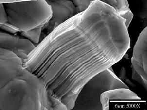
13 Effect of Deposit Thickness on Morphology microinch deposit microinch deposit Sulfate chemistry, supplier A, after TC 55C to 85C and 30C/90%RH (legs 10A and B)

14 Recrystallization in the Damaged Area Undamaged area Damaged area Sulfate chemistry, supplier A, after TC 55C to 85C and 30C/90%RH (leg 10B)


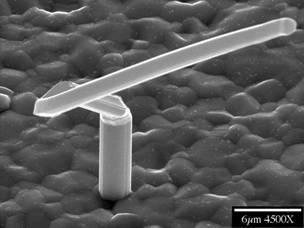
15 Temperature-cycled Thick Sulfate Leg 10 B early whisker growth Leg 12 B early whisker growth
16 Effect of Bath Chemistry (SOIC( SOIC s) Thin MSA Supplier A Thin MSA Supplier B Thin Sulfate Whisker density, per 300x field /95 30/90 TC-30/90TC-Amb Amb Aging conditions Longest whisker on 3 SOIC's /95 30/90 TC-30/90 TC-Amb Amb /95 30/90 TC-30/90 TC-Amb Amb Density Longest whisker, micron Density Longest whisker, micron Density Longest whisker, micron Thick MSA Supplier A Thick MSA Suppler B Thick Sulfate Whisker density, per 300x field /95 30/90 TC-30/90TC-Amb Amb Aging conditions Longest whisker on 3 SOIC's /95 30/90 TC-30/90 TC-Amb Amb /95 30/90 TC-30/90 TC-Amb Amb Density Longest whisker, micron Density Longest whisker, micron Density Longest whisker, micron
17 Effect of Bath Chemistry (brass( coupons) Set Cy: matte MSA Sn over brass (thin) Set Cx: Sulfate Sn over brass (thin) Density in 300x field /95 30/90 TC- 30/90 TC-Amb Aging conditions Amb Longest whisker, micron Density in 300x field /95 30/90 TC- 30/90 TC-Amb Aging conditions Amb Longest whisker, micron Density Longest whisker, micron Density Longest whisker, micron


18 Sample Set Cy 300X 1500X Leg 6 Cy 300+ small whiskers


19 Sample Set D: SnPb No Whiskers Secondary Electron Image Backscattered Electron Image Leg 13 D
20 Initial Findings In general, more whiskers grew with the -55C/85C temperature cycle method, followed by 60C/90%RH storage; some whisker growth was also observed with the ambient environment There is no indication in this experiment that thicker deposits are less prone to whisker Bath chemistry/plating process parameters seem to have the most significant influence on whiskering Slight advantage of sulfate-based chemistry comparing to a good-practice MSA bath Significant difference between two MSA-based processes from two suppliers All these observation may indicate that there are some unknown factors that have influence on whisker growth comparable with aging conditions Another conclusion maybe made that whisker growth phenomenon is multi-factorial event and the theory/model describing it should take into consideration numerous parameters
21 Recommended Test Method Prepare whisker test method for release by JEDEC. Purpose: Provide test method to aid in the evaluation and development of plating finishes. Provide an industry-standardized test for comparison of whiskerpropensity for different plating systems and processes. Not intended for use in reliability assessment or qualification. Recommended Test Methods: -55 C (+0, -10) / 85 C (+10, -0) air-air temperature cycle (20minutes/cycle) 60 C, 90±5%RH temperature / humidity storage Ambient storage (~23 C, %RH to be determined) All three tests are to be performed using separate samples
22 Future Work and Concerns Future work: Prepare whisker test method document for release by JEDEC. Validate and verify recommended test methods. Perform tests to extended durations (establish end points for recommended test methods). Attempt to identify test methods which can be correlated to application life (to attempt to define reliability and qualification tests). Concerns: How do we correlate whisker tests to application life (proof of quality & reliability)? How do we to utilize fundamental understanding to define an accelerated test? Are the proposed mitigation techniques effective?
23 Phase 3 DOE Validate and Verify Tests: -55 C (+0, -10) / 85 C (+10, -0) air-air temperature cycle (20minutes/cycle) 60 C, 90±5%RH temperature / humidity storage Ambient storage (~23 C, ~60%RH) Samples: Leaded packages from assembly contractors Sn, SnBi, SnCu and SnPb (control) finishes Copper CDA194, copper 7025, and Alloy42 leadframes For comparison include cells with Ni underplating (both matte and bright Sn) Fused (confirm melting) and/or annealed Sn Hot-dipped Sn JEITA test vehicle
24 Phase 3 DOE3 Tentative milestones Complete design of experiment (DOE) matrix May 30 Prepare samples Jun 27 Perform initial SEM Jul 18 Storage and temp cycle and regular inspections Sep 26 Analyze the data Oct 17 Prepare report Nov 14
25 Whisker Definition Purpose: To specify the physical and visual characteristics of a tin whisker for use in inspection (not intended as a metallurgical definition) Tin Whisker: A spontaneous columnar or cylindrical filament, which rarely branches, of tin emanating from the surface of a plating finish. NOTE, For the purpose of inspection tin whiskers have the following characteristics: an aspect ratio (length/width) > 2; can be kinked, bent, twisted; generally have a consistent cross-sectional shape; rarely branch; and may have striations/rings around it.

")

26 Whisker Examples Hillocks (Lumps) Odd-Shaped Eruptions (OSE) Whisker


27 Whisker Examples Consistent Cross-section Striations Rings


28 Whisker Examples Kinked Branched Initiating from Hillock
29 Inspection Protocol Scope: Establish an inspection method to quantify the propensity of an electroplated lead finish to develop tin whiskers. Examples of electroplated lead finish uses: terminals of ICs and passives, connectors, printed circuit boards, etceteras. Purpose: To recommend the equipment, locations and area of inspection, sample size and procedure for inspection. Equipment: Scanning Electron Microscope (SEM) is recommended for whisker inspection and verification.
30 Inspection Protocol Procedure: Use carbon tape, paint, or other conductive material to attach the sample to the work holder to prevent charging. When handling the samples, care must be taken to avoid contact with the electroplated finish. Contact with the finish may detach whiskers. Inspect each sample for whiskers at a magnification of 300X. The samples should be mounted in the best position (maximize inspection areas and view of critical locations such as bends) for SEM inspection. At each inspection: Record the presence of hillocks, odd-shaped eruptions and whiskers (whiskers 10 microns in length or > 2 in aspect ratio). Estimate and record the length of the longest whisker. Whisker length is measured from the termination/electroplate surface. Use higher power as necessary to determine length. Record the whisker density representative of the level of whisker growth (number of whiskers within a 250µm X 250µm area).
31 SEM Inspection Set-up Carbon Tape Package Live Bug SEM Work Holder
32 Inspection Protocol Recommended Sample Sizes: Example: Leaded Packages Inspect all plated surfaces, as practical, of 3 leads on a minimum of 3 packages randomly chosen from the test samples. Top Side 2 Side 1
33 Inspection Protocol Recommended Sample Sizes: Example: Test Coupons Inspect 3 locations on a minimum of 3 coupons randomly selected from the test samples. The area inspected at each location should be the field of view at 300x (approximate area 250 µm X 250 µm). Coupon 3 Inspection Locations
34 Inspection Protocol Recommended Sample Sizes: Example: Passive Chipcaps/resistors Inspect the 3 visible sides and end of each termination on a minimum of 3 samples selected at random.
35 Overview of Committee Effort Direct: Completed two comprehensive matrices, Phase 1 and 2, both for ICs and Passives. Identified three test methods recommended for plating finish development and characterization. Proposed a definition for whiskers. Developed an inspection protocol. Initiated test method document for potential release by JEDEC. Preparing matrix for Phase 3 DOE (validation and verification). Indirect: Generated considerable momentum to understand whiskers and tin plating globally.
36 Recommended Test Method Recommended Test Methods: -55 C (+0, -10) / 85 C (+10, -0) air-air temperature cycle (20minutes/cycle) 60 C, 90±5%RH temperature / humidity storage Ambient storage (~23 C, %RH to be determined) All three tests are to performed using separate samples Still need further verification, acceleration factors