Bypassing Problems related to water cooling Case studyforiltec in EAF. AISTech18, 9 th May 2018
|
|
|
- June O’Connor’
- 5 years ago
- Views:
Transcription


1 Bypassing Problems related to water cooling Case studyforiltec in EAF AISTech18, 9 th May 2018


2 Mettop Group Organigramm 50.0 %


3 Mettopat a Glance Meet customers problems tailor-made process optimization Tankhouse Engineering Furnace Integrity Cooling Technology METTOP-BRX Technology Basic Engineering Detail Engineering Feasibility Studies Consulting decreasing OPEX Consulting increasing Current Efficiency Process Modelling CFD Simulation Gas Purging Systems 3D Refractory Engineering Cooling Solutions ILTEC Technology Feasibility Studies

4 Cooling Technology Revolutionary new: Ionic Liquid Cooling Technology (ILTEC)

5 FurnaceIntegrity Optimized safety CFM Cooling Composite Furnace Module
 accidents caused by water coming into contact with liquid metal happen")

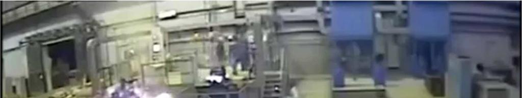
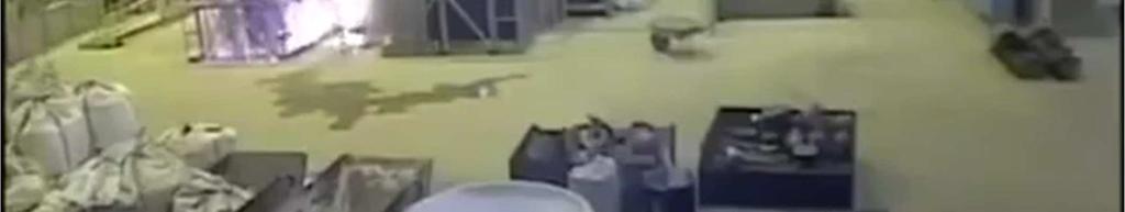
6 ILTEC Technology Why rethink cooling solutions? Over 200 documented (!!!) accidents caused by water coming into contact with liquid metal happen every year. Water + liquid metal = 1700 times volume expansion plus potential oxyhydrogen reaction Norway 1 fatality 2007 China 16 dead, 64 injured


7 Weshalb das Überdenken von Kühllösungen wichtig ist? Source: Harmen Oterdoom, FURNACE EXPLOSIONS WITH A FOCUS ON WATER


8 Ionic Liquid IL-B2001 Optimized properties Almost no vapour pressure below decomposition temperature Not flammable below decomposition temperature Non toxic Non corrosive
9 Ionic Liquid IL-B2001 Characteristic properties Symbol Value Unit Range Operation temperature [ C] ΔT = 150 C Short term stability 250 [ C] Decomposition temperature 450 [ C] Minimum operation temperature -10 [ C] Crystallization temperature [ C] Density ρ [kg/dm 3 ] C Specific heatcapacity c p [J/gK] C Dynamic viscosity η 20 5 [mpa s] C Electrical conductivity κ [ms/cm] C Q [W] = ṁ [m/s] cp [J/gK] ΔT [K] Lower specific heat capacity can be compensated due to a higher temperature range and enables a heat transfer comparable to water (c p =4.19[J/gK]).


10 Ionic Liquid IL-B2001 Optimized properties


11 Ionic Liquid IL-B2001 Optimized safety Industrial scale tests with IL-B2001 introduced into liquid steel melt No reaction when liquid steel melt gets in contact with IL-B2001 Improved safety standards


12 ILTEC Technology Re-defining the term safety and becoming Best Available Technology (BAT) Cooling withil-b2001 Water cooling Likelihood Negligible Unlikely Seldom Possibe Often Accidents happen from time to time When exchanging water by IL-B2001 -> explosion free environment that allows cooling in a safe and sound manner Probability remains at the same level BUT the extent of consequences can be tremendously shifted towards a decreased impact The diagram shows the path of becoming best available technology Insignificant Minor Significant Major Severe Consequences


13 ILTEC Technology Possible applications of ILTEC-Technology with IL-B2001 Substitution of water in existing systems Blast furnace taphole, formerly cooled with water Newcooling applications Possibility of heat recovery Tuyere zone of Peirce Smith Converter, no cooling so far because of danger Sufficient heat transfer and higher outlet temperature of up to 200 C enable heat recovery
 guarantee the flow of the IL through the entire pipe system Two heat exchangers to remove the heat to the secondary cooling")
14 ILTEC Technology Hardware Main components: Tankfilled with IL-B2001, the freeboard volume above the liquid level is purged with nitrogen to prevent hydration of the liquid through moisture in the air Two identical pumps(one for redundancy in case of breakage or malfunction) guarantee the flow of the IL through the entire pipe system Two heat exchangers to remove the heat to the secondary cooling circuit, again one in operation, one for redundancy Numerous measuring devices (digital as well as analogue) throughout the entire system to measure temperature, flow, pressure and differential pressure Variety of valves, adjusting wheels and shut-off devices for all different operation modes
15 ILTEC Technology References of industrial scale use
16 ILTEC Technology References of industrial scale use Application Benefit Supply lines Cooling of shaft partof plasma furnace Guaranteeing higher temperature inside the furnace for preventing corrosion from sulfuric acid Overall flow capacity Country Start Up 3 30m 3 /h Norway January 2015 Blast furnace tap hole Increasing safety 2 30m 3 /h Germany October 2015 Test for cooling EAF bottom shell Coolingof pipes of copper coolersduring the casting process Coolingof connection flanges at the RH degassing vessel Coolingof a permanent charging lance and camera at TBRC converter Test at tuyere zoneof copper converter Increasing the lifetimeof refractory beneath bath level Increasing process safety and improve copper cooler quality Increasing process safety and prevent warping Increasing process safety and allowing a permanently remaining lance in TBRC Increasing lifetime of tuyere zone 2 20m 3 /h Germany Testsperformed in Summer m 3 /h Spain January m 3 /h Austria June m 3 /h Germany June m 3 /h Canada June 2018

")
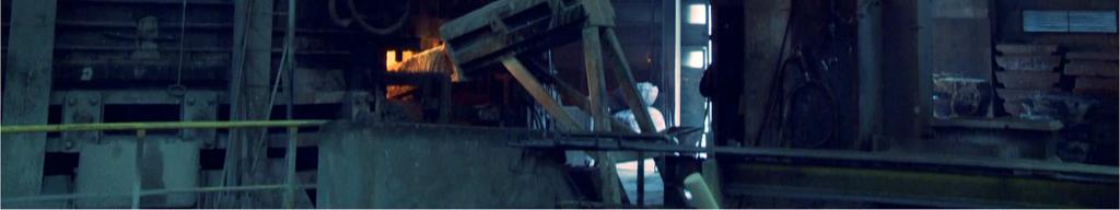
17 Blast Furnace Taphole Substitution of water in existing taphole Taphole cooling Blast Furnace ArchelorMittal, Bremen (Germany) since October 2015


18 ILTECTechnology Industrial scale application at Blast Furnaces CFM Modelling Temperature distribution during tapping and during normal operation Temperature distribution during tapping and during normal operation

19 ILTEC-Technology Industrial scale application at a zinc oxide furnace (Høyanger, Norway)
20 ZincOxide Furnace Industrial scale application for side wall cooling at higher temperatures Cooling of furnace walls For preventing temperatures below the dew point, installed at Nyrstrar(Norway) and in operation since January 2015 No corrosion of the steel structure due to selective cooling to temperatures of 180 C and hence preventing of condensation of sulfuric acid Increase in lifetime of entire vessel


21 ILTEC Technology Hardware as installed in Hoyanger


22 RH Degassing Industrial scale application at a steel vacuum degassing system Cooling of all flanges as the connection parts between nozzle and lower part and lower and upper part for increased operating safety at voestalpine DonawitzGmbH, Austria.
 Dimensioning and Capacity System Media Supply Number supply lines Piping dimension supply lines Piping dimension facility Cacapity pumps Maximum Flow Maximum heat removal")
23 ILTECTechnology For cooling the copper piping during casting of copper coolers, Spain Start-up date Actual Application Jan 18 Cooling of copper pipes during casting Former applications Outer dimensions (l x b x h) Dimensioning and Capacity System Media Supply Number supply lines Piping dimension supply lines Piping dimension facility Cacapity pumps Maximum Flow Maximum heat removal Heizkabel Capacity instantanuous heater Tank volume Water Supply Piping dimension water supply Current/Frequency Power Supply Full load current 2,5 x 1,6 x 2,5 m 2,5 x 1,6 x 2,5 m 4 DN40 DN80 20 m 3 /h + 30 m 3 /h 50 m 3 /h 2x kw --- 7,5 kw + 30 kw 400 dm 3 max. 100 m 3 /h DN100 3x 400/ Hz 45 kw 65 A


24 ILTECTechnology For tuyere zone cooling of converter Value Unit Individual supply lines Maximum pumping capacity 20 m 3 /h Capacity heat exchanger 400 kw Inlet temperature IL-B C Piping dimension facility DN50 Piping dimension supply lines DN40 Tank volume 250 dm 3 CFM copper cooling element, comprising of two individual copper parts, connected with a steel construction. In between the copper parts, the AlCrtuyere bricks are inserted and in the final construction stage the castablerefractory mass in casted upon the copper fingers. Start up in summer 2018

25 ILTECTechnology For charging lance cooling in a TBRC converter Start up in June 2018 ILTEC facility with two individual supply lines for cooling of the permanent charging lance and the camera installed in the TBRC converter. Start up in June 2018
26 ILTEC Technology For use in EAF
27 Concept for EAF Cooling Solution for entire EAF ILTEC Roof and off-gas duct ILTEC Side Wall Panels UpperShell ILTEC Side Wall LowerShell
28 ILTEC Technology in EAF Upper shell cooling to increase safety Benefits: Increased safety because of a water-free furnace area Decreased damagein case of leakage due to the lack of volume expansion and explosion Fast leak detection in case of individual supply and supervision of each panel Avoidance of hydration of refractory of the bottom vessel in case of leakage Easy, fast and safe repair work in case of breakage
29 ILTEC Technology in EAF Upper shell cooling to increase safety
30 ILTEC Technology in EAF Upper shell cooling to increase safety Option 1 Option 2 Unit Supply lines cooling panels Total flow rate IL-B Temp. difference average (peak) 15 (30) 15 (30) C m 3 /h Cooling load average (peak) 2500 (5000) 2500 (5000) kw Inlet temperature IL-B C Outlet temperature IL-B2001 (peak) 65 (80) 65 (80) C Amount of IL-B kg
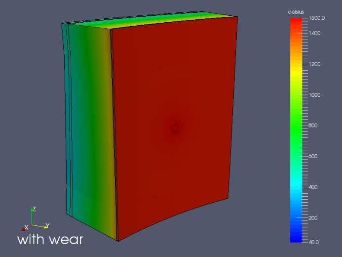
31 ILTEC Technology in EAF Lower shell cooling to increase vessel lifetime Benefits: Intensified cooling steep temperature gradient, less infiltration zone Less wear increased lifetime of refractory Decreased down time more productivity Decreased repair work/gunning lower production costs Increased safety for employees and systems Increased inner furnace diameter by decreasing refractory thickness


32 ILTEC Technology in EAF Lower shell cooling to increase vessel lifetime CFM cooler Slag spout Slag level Liquid steel bath Sill level Plate cooler Gas purging plug
![ILTEC Technology in EAF Lower shell cooling to increase vessel lifetime Initial brick thickness[mm] Remaining brick thickness[mm] Area without cooling(1) 1.+2.](/docs-images/94/121325208/images/33-2.jpg "Layer 3.+4. Layer 450 450 0 319 0 71 5. Layer 500 494 99 Area of copper panel(2) 1.+2. Layer 350 20 6 3.+4. Layer 350 330 94 5.")
33 ILTEC Technology in EAF Lower shell cooling to increase vessel lifetime Initial brick thickness[mm] Remaining brick thickness[mm] Area without cooling(1) Layer Layer Layer Area of copper panel(2) Layer Layer Layer Slag Remaining thickness [%]
34 ILTEC Technology in EAF Lower shell cooling to increase vessel lifetime
35 ILTEC Technology in EAF Off-gas duct cooling for heat recovery Benefits: Heat recovery due to outlet temperature of up to 200 C Bypassing corrosion problems in cold spots Increased safety for employees and systems (no water in the furnace in case of leakage)
36 ILTEC Technology in EAF Off-gas duct cooling for heat recovery
37 ILTEC-Technology 37 Let s think out of the box!