CONTENTS Of the ROVELD P 315 B MANUAL 1. Introduction 2. Introduction for the welding process 3. Drawings and part lists of single machine parts of th
|
|
|
- Whitney Price
- 5 years ago
- Views:
Transcription

1
2
3

4
5
6

7

8

9

10

11

12
13
14
15

16

17

18

19

20

21

22

23

24
25

26

27

28

29

30
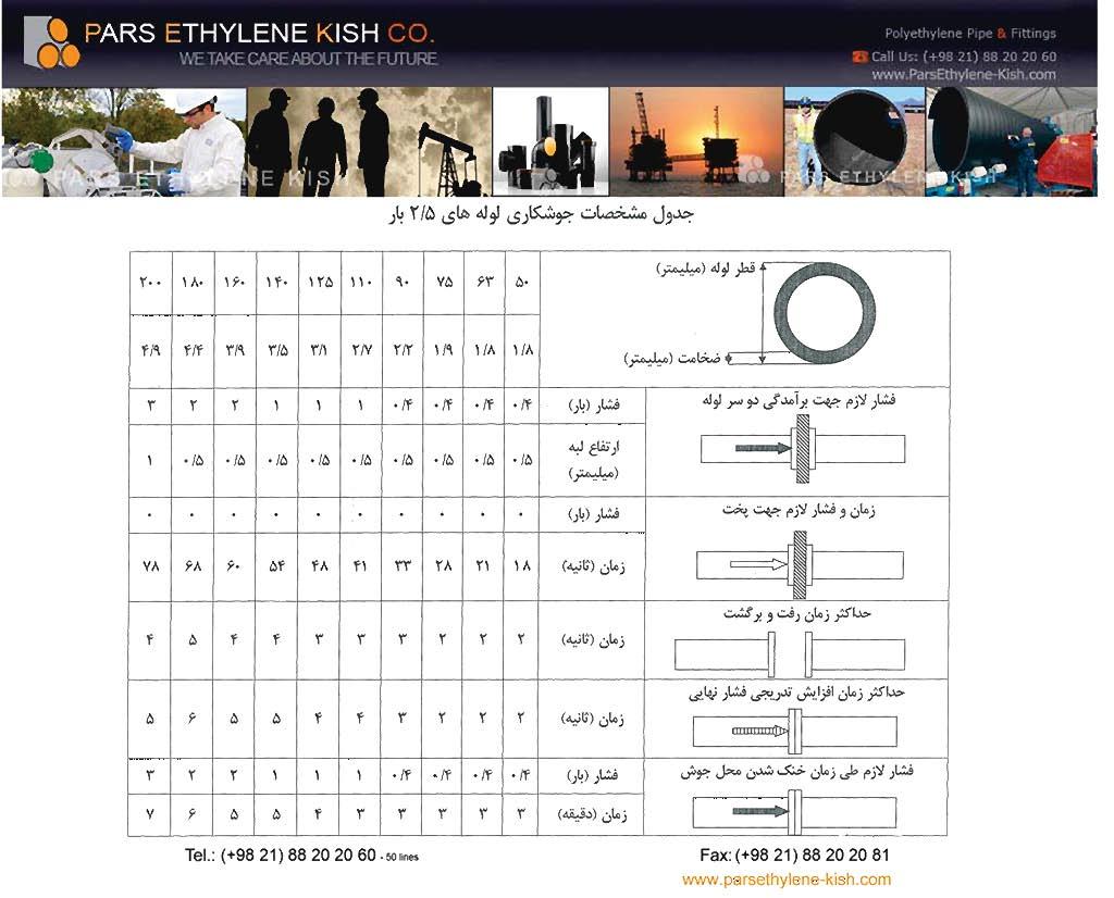
31 CONTENTS Of the ROVELD P 315 B MANUAL 1. Introduction 2. Introduction for the welding process 3. Drawings and part lists of single machine parts of the Roweld P 315 B a) Basic Machine b) Milling Equipment c) Heating Element d) Hydraulic Unit e) Hydraulic hoses f) Control and Connection case g) Flange Adaptor (accessory) 4. Instruction for the ROWELD P 315 B 5. Pressure Table (Look at enclosed DIN A5 folder) 6. Welding Conditions 7. Maintenance Instructions 8. Safety Rules 9. Catalog
32 Introduction of the manual for ROWELD P 315 B Dear customer, We congratulate you to the purchase of a Parsethylene Kish Roweld P 315 B You decided to buy a machine that we product with a high quality level, Capable to meet all requirements of the foreseen applications. This machine type belongs to the "new generation and we could make remarkable improvements in quality and product sections. The most important improvements are described below and we want to bring them to your attentionbecause you should not abandon on a more of quality. Important improvements: - Machine frame of basic machine is stronger and more rigid - Piston shafts are made out of stainless steel: a test with about strokes(under load) did nۥt show a fading in quality or function - The milling cutter is equipped with a limit switch in order to prevent starting the cutter outside of the machine. - Better surface and a better high quality PTFE-coting on the heating element: - Heating element, milling cutter and hydraulic unit will be connected with the new connection and control box so that there is only need for one electrical cable. The electronic temperature control is integrated into the control box and protected against dirt, heat and shocks. - Reusable transport box for durable storage and transport of the machine with partitions for keeping the clamping inserts. To maintain the level of quality for a long time pleas respect and follow the operating and maintenance instructions.
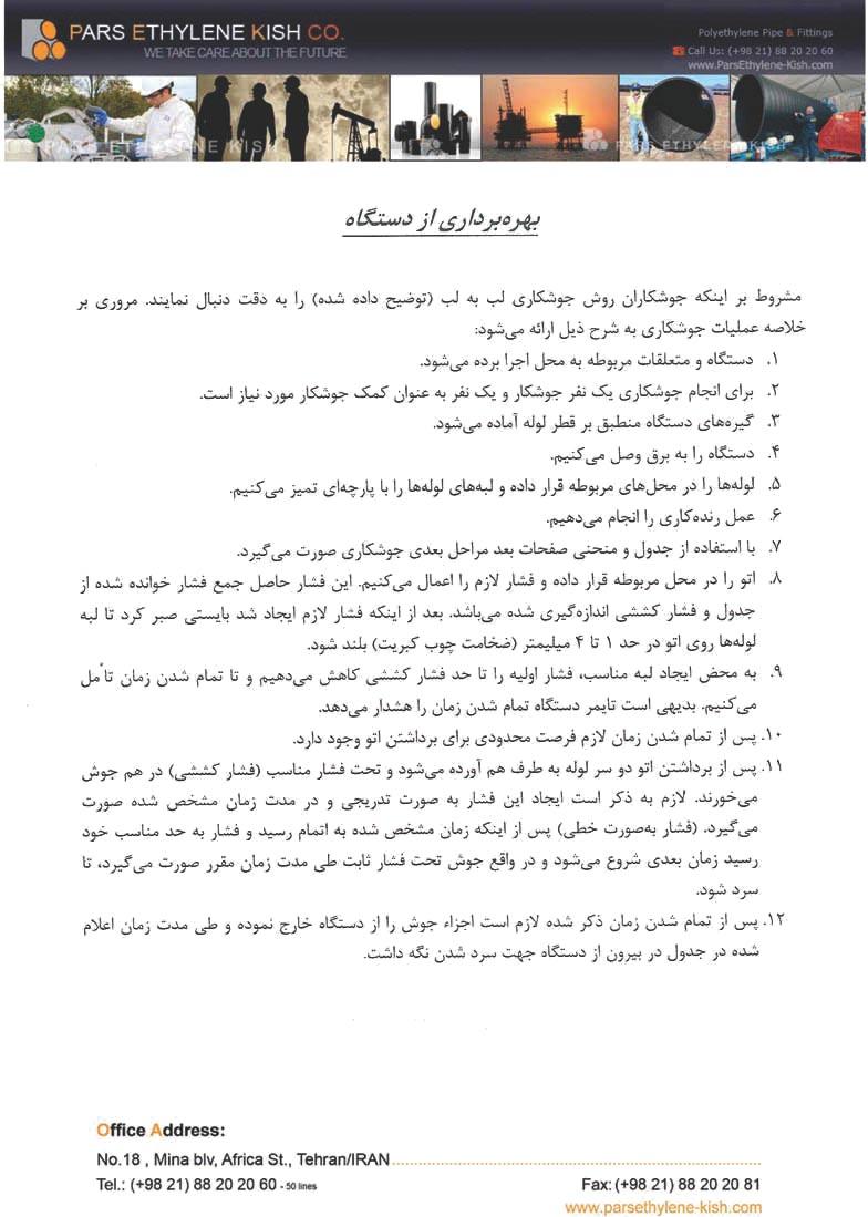
33 Instruction for the Welding process Hot plats butt welding (according to DVS-regulations) 1. Set up the machine and switch on all units. 2. If necessary erect welding tent or some thing similar. 3. Clamp in the parts which are to be welded. 4. Set milling equipment. 5. If there are long pipes. The pipes have to be supported by rollers or similar equipment. 6. Trim parts which are to be welded. 7. Take out the milling cutter. 8. Remove swarf without dirtying trimmed parts. 9. check whether parts are trimmed correctly by closing pipes (gap mm accord. To pipe diameter). 10. Check pipe alignment (max. 10% of wall thickness). 11. The surfaces of the heating plate have to be cleaned with a piece of paper or cloth (free of dust or fluff) with white spirit. 12. Check the welding temperature (PEHD 210 deg +/- 10 deg. C). try to react the lower range of temperature if there is a wall thickness of more than 12 mm. 13. Check the drag pressure and add the welding pressure. 14. Place the heating plate in the machine. 15. Press the surfaces which are to be welded together (according to the figure for the alignment) to the heating plate until there is a bead on the whole perimeter ( mm according to the wall thickness). 16. Reduce the pressure for the heat soak time to nearly zero. 17. After heat soak time (heating time is corresponding to wall thickness) open the machine and take out the heating plate without damaging the melted surface. 18. Close together the connecting surfaces immediately (3-20 sec.acc. to pipe diameter). 19. Increase the welding pressure from zero to the limit (in 3-35 sec.). 20. Now there is a cooling time (4-45 min. according to the pipe wall thickness) but the welding pressure has to remain. 21. At the end of the cooling time the welded parts can be removed from the machine.
34 Operating Instructions for Roweld P315 B Starting operations 1. Connect basic machine and hydraulic unit with the two hydraulic hoses. 2. Connect the plug of control box to power supply. Connect the plugs of milling cutter, hydraulic unit and heating element to control box. Take care that the plug of the heating element is fixed well into the control box by the locked safety mechanism. Loosen the screws of the PVC-cover of the control box and remove it. Press down green start button the temperature control knob. Advised temperatures differ from country to country Preparation for welding 3. for pipes which are smaller than 250 mm Dia. Appropriate clamping inserts (8 half sections made out of aluminum) have to be placed together with the clamping inserts 250 mm wide (8 half sections made out of aluminum) into the basic clamps. For 280 mm pipes the clamping inserts will be placed directly into the basic clamps. 4. Place the pipes of fittings into the clamps and tighten the hexagonal brass nuts of the upper clamps. Eggshapeness of the pipes can be eliminated by thightening or loosening the upper clamps. 5. Close the pipes together under reguired pressure and check that. They are fixed well into the clamps. Also check that the heating element has reached the required temperature. (the working temperature is reached when the red control lamp turns on and off in intervals) Welding process 6. Place the milling cutter between the two pipes which must be welded. Switch on hydraulic unit.
35 Operating Instructions for ROWELD P 315 B By moving the operating lever gently press the ends of pipes against the rotating cutters of the milling unit. To prevent damages on the electrical drive it has to be welded with low contact pressure. The contact pressure can be adjusted by using the pressure adjusting valve. 7. The milling operation is complete when the swarf
36 Operating instructions for Roweld P 315 B The drag pressure indicated on pressure gauge when moving the machine must be added to the welding pressure stated in pressure table and must be computed prior to welding. 12. For pipe to pipe joins the distance blocks have to be fixed in both left clamping elements. For pipe to fitting joints the distance blocks have to be fixed in both centre clamping elements, so that the pipe is fixed by 3 basic elements and the fitting by one. The third basic clamp can be individually moved on the shafts in order to get the necessary space for clamping and welding. 13. By using heating element and milling cutter damages on the two guiding shafts should be avoided. 14. For welding flanges we do recommend the use of our special flange adaptor in order to get a exact alignment of the flange to the pipe.
37 Welding conditions 1. The welding area has to protected from all weathers (e.g. and temperatures below 0 deg. C). The operator has to be sure that there is a sufficient temperature for the wall of the pipe. If necessary the pipes have to be warmed. This can be done by putting up a welding? and to heat this. If this is possible, the welder can work at any outside temperature. If necessary the welder has to make a test join under the mentioned condition to get an additional proof. 2. If the pipe is warmed up uneven by irradiation a temperature balance has to be made by covering in time in the area of the welding point. 3. There has to be no damage on the surfaces which are to be welded together. They also have to be clean from dirt, oil, swart. The cleaning of the surfaces has to be made just before the welding. 4. There has to be no disturbance during the welding and also during the cooling time. 5. The whole welding process has to be controlled. We recommend to Note the welding figures for each section of the building site in a welding report. The figures should be separated from diameters.

38 Maintenance Instructions ROWELD P 315 B The following conditions for the maintenance of machine should be observed: 1. The chromium plated guide shafts on the basic machine must be kept free of dirt. 2. The electric motors on milling unit, hydraulic unit and the heating plate require a 220 V AC 50 cycle supply. 3. The heating plate should be kept free of dirt and dust. Therefore it should be cleaned frequently with a fluff free cloth soaked with white spirit. 4. The oil tank of the hydraulic unit must always be kept filled with hydraulic oil, otherwise the pump can be damaged. Use only high quality oil (viscosity 68 deg. 150 at 20 deg C-DTE 26). 5. The quick action couplings on the hydraulic parts of the machine should be kept free of dirty by using the enclosed protection caps. 6. The blades of the milling cutter must be checked from time to time. Worm blades must be either turned over (they are double sided) or replaced.