Explosive Testing of Open Cylinders for Verification of Composite Properties used in Computational Analysis
|
|
|
- Erik Craig
- 5 years ago
- Views:
Transcription
, Jagadeep Thota, University of Nevada, Las Vegas ASME 2012 Verification and Validation")
1 Explosive Testing of Open Cylinders for Verification of Composite Properties used in Computational Analysis Stacy Nelson, Ph.D. Sandia National Labs, Livermore CA Brendan O Toole (presenter), Jagadeep Thota, University of Nevada, Las Vegas ASME 2012 Verification and Validation Symposium May 2-4, 2012 Las Vegas, NV
2 General Motivation and Approach There is a need for: Accurate composite failure prediction in computational model Dynamic component experimental data for validation of modeling procedure Typical Problem: Thin-walled structure subject to impact or blast loading Desire accurate prediction of peak strains and deformations Prefer shell element based model for faster design optimization Example: Explosively Loaded Cylinder Loads: Efficient Modeling of Blast Materials: Steel Laminated Composites Strain Rates: Intermediate ( )
3 Symmetry Boundary Conditions Symmetry boundary conditions used for efficiency
4 Simplified Model of Explosive Material All air blast were modeled with CONWEP Developed by US Army to calculate conventional weapons effects Blast Behavior Characterized by Friedlander s Equation Pressure P max t + Time LS-DYNA implements Friedlander s equation for TNT User defines mass of TNT location of explosive time of detonation surface interacting with blast
5 Metallic Material Model Modeled with *MAT_PLASTIC_KINEMATIC Bi-linear elastic-plastic model with failure prediction capabilities First linear portion represents the elastic region Second linear portion represents the plastic region Modeled materials deform according to the bi-linear stress-strain relationship until the simulated strain exceeds the failure strain Elements are deleted from the model when the failure strain is surpassed Minimum Required Properties Density Elastic Modulus Poisson s Ratio Yield Strength Tangent Modulus Failure Strain

6 Composite Material Model Modeled with *MAT_ENHANCED_COMPOSITE_DAMAGE Predicts composite failure with Chang-Chang criteria tensile fiber failure compressive fiber failure tensile matrix failure compressive matrix failure Complete failure occurs only after tensile fiber failure Composite stiffness is adjusted after other failure modes Minimum Required Properties Density Longitudinal Modulus Transverse Modulus Major Poisson s Ratio Shear Modulus Longitudinal Compressive Strength Longitudinal Tensile Strength Transverse Compressive Strength Transverse Tensile Strength Shear Strength

7 Contacts for Composite Lamination Each ply of the composite is modeled with separate shell elements Delamination simulated with a tiebreak contact in 2 stages: Stage 1: plies are perfectly bonded until the tiebreak failure occurs Combination of normal and shear strength values Stage 2: After delamination, the contact algorithm switches to a surface-to-surface contact σ n : σ s : NFLS: SFLS: Stress in normal direction Stress in shearing direction Normal strength of bond Shear strength of bond
8 Case 1: Simulating Elastic Response Experimental data provided by Russian Federal Nuclear Agency (RFNA) Cylindrical composite shells with spherical internal load Basalt/epoxy composite Properties required for MAT 54 supplied by RFNA Circumferential strain recorded with high-speed photochronography Pulse light source used to create a photographic image of deformation
9 Case 1: Experimental Configuration RFNA cylinder test # mm 135 g TNT 600 mm 161 mm g of explosive causes visible circumferential strain oscillations (no failure recorded) 5.9 mm 3.8 mm 3.8 mm

10 Case 1: Simulation Approach Finite element model of cylinder #261
11 Case 1: Mesh Refinement Mesh density study Element Size Predicted Peak Strain Computational Time 6.0 mm 1.281% 103 s 4.0 mm 1.298% 318 s
12 Case 1: Comparison of Experiments and Simulation Computational model under predicts initial peak by 12% Period of oscillation matches indicating good mass and stiffness
 MAT 54 properties provided by UCSI and literature")
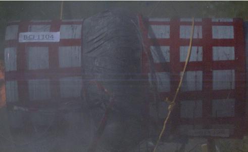
13 Case 2: Picatinny Arsenal Testing Explosive testing of six E-glass/ Vinylester composite tubes Deformation was measured with high-speed photography Best experimental data recorded for cylinder tests #4 and #5 Cylinders manufactured by Utility Composite Solutions International (UCSI) MAT 54 properties provided by UCSI and literature #4 #5


14 Case 2: Experimental Configuration High speed camera was protected by a steel enclosure Cylinders were loaded with centrally placed charges of C4, positioned with light-weight foam blocks

15 Case 2: Composite/Metallic Cylinder (#4) Outer layer of E-glass composite with inner liner of AISI 1008 Material properties for MAT 3 taken from literature Experimental testing completed with ~300 g of C4 Significant amount of observed deformation and composite failure Innermost and outermost composite plies in the central region completely ablated upon detonation Central region would radially expand, causing a decrease in length Steel material would plastically deform Reduction in length is permanent 400

16 Case 3: FEA Model of Composite/Metallic Cylinder (#4)
17 Case 3: Mesh Refinement Element Size Predicted Minimum Length Computational Time 6.0 mm mm 1320 s 4.0 mm mm 2520 s


18 Case 3: Comparison of Results
19 Case 3: Summary of Results Model accurately predicts the peak deformation 1% difference between model and experiment Two differences between experiment and model Computational model contracts to a maximum deformation faster Model may be stiffer than the actual test cylinder Composite inconsistencies cannot be detected and accounted for in model CONWEP blast function. Predicted blast time-of-arrival and pressure wave profile may vary slightly from the experiment Computational model rebounds slightly after the peak deformation Less than 5.0 mm A similar rebound may have been present during the physical explosive testing minimum resolution of the high speed camera = 1.5 mm
20 Summary and Conclusions An efficient analytical technique to predict the peak strains and deformations of blast loaded composite structures was created Case Study 1: Elastic Response Excellent agreement with experimental data Shell elements are capable of capturing the relatively small displacements Tiebreak contacts correctly simulate the composite lamination and stiffness LS-DYNA composite material model accurate for smaller amounts of deformation CONWEP blast function is capable of approximating lower level blasts Case Study 2: Composite/Steel Cylinder High Deformation Response Model simulated explosive test completed at Picatinny Arsenal Accurate prediction of complete test duration Thin steel liner plastically deforms and overall composite displacement is limited Case studies demonstrate accurate simulation of complete elastic response and accurate prediction of peak deformations when the response is post-failure Future Work Rebound behavior of damaged all-composite vessel needs additional work Experimental data collection during explosive tests can be improved
21 Questions Thank You!
22 Case 3: All Composite Cylinder (#5) Experimental testing completed with 180 g of C4 C4 to TNT conversion of 1.2 Significant amount of observed deformation and composite failure Innermost and outermost composite plies in the central region completely ablated upon detonation Central region would radially expand, causing a decrease in length Length reduction most measurable deformation After maximum length reduction, the cylinder would spring back out Mechanical energy stored in the unbroken fibers

23 Case 3: All Composite Cylinder (#5) Assumptions were made to facilitate the use of the CONWEP blast function During actual testing, the central section of the innermost layers of ±88 fibers were completely ablated upon detonation. When modeled with CONWEP, this behavior is accurately simulated Elements in the central area of the shell layer representing the ±88 plies are completely deleted. Transference of blast pressure to remaining composite plies in the central zone is lost Central region of the innermost ±88 plies are omitted from model CONWEP blast pressure is applied to the ends of the innermost ±88 plies and the central region of the innermost ±15 plies.
24 Case 3: All Composite Cylinder (#5) Comparison of models with and without central section of ±88 completed to verify assumptions Model with the complete layer of ±88 plies contracts much less and rebounds much sooner Stiffness of structure minimally effected by omission Slight difference in the radial displacements experienced by the two models
25 Case 3: All Composite Cylinder (#5) Mesh density study Element Size Predicted Minimum Length Computational Time 6.0 mm mm 4438 s 4.0 mm mm s 3.0 mm mm s

26 Case 3: All Composite Cylinder (#5) Results of the 4.0 mm model were compared to experimental results
27 Case 3: All Composite Cylinder (#5) Model accurately predicts the peak deformation 2% difference in the peak length deformations Two differences between the experiment and model Computational model contracts to a maximum deformation faster Model may be stiffer than the actual test cylinder Composite inconsistencies cannot be detected and accounted for in model CONWEP blast function Predicted blast time of arrival and pressure wave profile may vary slightly from the experiment Computational model does not completely rebound after the maximum contraction Likely related to composite material model Tensile matrix failure mode present throughout the structure after the partial rebound» Depletes remaining elastic energy from the unbroken fibers» Not present during actual testing