INVERTER MMA DC WELDING MACHINE WD U WD WD WD WD A/160A/180A/200A/250A
|
|
|
- Kenneth Caldwell
- 5 years ago
- Views:
Transcription


1 INVERTER MMA DC WELDING MACHINE WD U WD WD WD WD A/160A/180A/200A/250A
2 WD U/WD /WD /WD /WD Thank you for purchasing a VIDO product. We are confident that you will appreciate the quality of the product and you will be entirely satisfied with your purchase. Please read carefully the user safety and operating instruction on how to operate this product correctly within safety norms and regulations.
3 WD U/WD /WD /WD /WD


4 WD U/WD /WD /WD /WD x
5 COMPONENT LIST 1) - output terminal 2) Current meter 3) Handle 4) Power indicator light 5) Welding current selector 6) Protection indicator light 7) + output terminal 8) Power switch 9) Electrode holder with cable 10) Ground clamp with cable NORMAL ACCESSORIES 1) Electrode holder with cable: 1pc 2) Ground clamp with cable: 1pc 3) Protective mask: 1pc 4) Hammer brush: 1pc 5) Belt: 1pc We recommend that you purchase your accessories from the same store that sold you the welding machine. Use good quality accessories marked with a well-known brand name. Choose the type according to the work you intend to undertake. Refer to the accessory packaging for further details. Store personnel can assist you and offer advice.
6 WELDING MACHINE SAFETY WARNINGS Warning: Read all safety warnings and all instructions. Failure to follow the warnings and instructions may result in electric shock, fire and/or serious injury. Save all warnings and instructions for future reference. Electric shock can kill. Electric arc welders can produce a shock that can cause injury or death. Touching electrically live parts can cause fatal shocks and severe burn. While welding, all metal components connected to the wise are electrically live. Poor ground connections are a hazard, so secure the ground lead before welding. Wear dry protective apparel: coat, shirt, gloves and insulated footwear. Insulate yourself from the workpiece. Avoid contacting the workpiece or ground. Do not attempt to repair or maintain the welder while the power is on. rea as possible. Do not touch the welding wire and the ground or grounded work piece at the same time. Do not use a welder to thaw frozen pipes. welder not in use. Fumes can be dangerous. Fumes emitted from the welding process displace clean air and can result in injury or death. Do not breathe in fumes emitted by the welding process. Make sure your breathing air is clean and safe. Work only in a well - ventilated area or use a ventilation device to remove welding fumes from the environment where you will be working. Do not weld on coated materials (galvanized, cadmium plated or containing zinc, mercury or barium). They will emit harmful fumes that are dangerous to breathe. If necessary use a ventilator, respirator with air supply or remove the coating from the material in the weld area. The fumes emitted from some metals when heated are extremely toxic. Refer to the material safety data sheet for the manufacturer s instructions. Do not weld near materials that wil l emit toxic fumes when heated. Vapors from cleaners, sprays and degreasers can be highly toxic when heated. Arc rays can burn eyes and skin. The welding arc produces ultraviolet (UV) and infrared (IR) rays that can cause injury to your eyes and skin. Do not look at the welding arc without proper eye protection. ear.
7 use a shade 10 lens; for above 160 A, use a shade 12 lens. - retardant cloth or leather shirts, coats, pants or coveralls are available for protection. other people from the arc rays emitted from your welding. themselves. Welding can cause fire or explosion. Do not weld on containers or pipes that contain or have had flammable, gaseous or liquid combustibles in them. Welding creates sparks and heat that can ignite flammable and explosive materials. Do not operate any electric arc welder in areas where flammable or explosive materials are present. Remove all flammable materials within 10m of the welding arc. If removal is not possible, tightly cover them with fireproof covers. Take precautions to ensure that flying sparks do not cause fires or explosions in hidden areas,cracks or areas you cannot see. Keep a fire extinguisher close in the case of fire. Wear garments that are oil-free with no pockets or cuffs that will collect sparks. Do not have on your person any items that are combustible, such as lighters or matches. Keep work lead connectedas close to the weld area as possible to prevent any unknown,unintended paths of electrical current from causing electrical shock and fire hazards. To prevent any unintended arcs, cut wire back to 6mm stick out after welding. m holder or cut off welding wire at contact tip when not in use. Hot materials can cause severe burns. Welded materials are hot and can cause severe burns if handled improperly. Do not touch hot welding materials with bare hands. Do not touch gunnozzle after welding until it has had time to cool down. Flying metal can injure eyes. Welding creates hot sparks that can cause injury. Chipping slag off welds creates flying debris. Wear protective apparel at all times: Approved safety glasses or shield, welder s hat and ear plugs to keep sparks out of ears and hair. Magnetic fields can affect pacemakers. Electromagnetic fields can interfere with various electrical and electronic devices such as pacemakers. Consult your doctor before using any electric arc welder or cutting device. Keep people with pacemakers away from your welding area when welding.
8 Do not wrap cable around your body while welding. Noise can damage hearing. Noise from some processes or equipment can damage hearing. Extension cables Using extension cables is not recommended. The use of extension cables will cause voltage to drop. If an extension cable must be used, be sure it is: A 3-wire extension cable that has a 3-blade grounding plug, and a 3-slot receptacle that will accept the plug on the product. In good condition. The section of the cable should be bigger to reduce the lower of the cable voltage. GROUNDING INSTRUCTIONS This welding machine should be grounded while in use to protect the operator from electric shock. The welding machine is equipped with a three-core cable and grounding type plug to fit the proper grounding type receptacle. The green and yellow or green conductor in the cable is the grounding wire. Never connect the green and yellowor green wire to a live terminal. IMPORTANT NOTE Be sure the supply is the same as the voltage and frequency given on the rating plate. Remove the main plug from socket before carrying out any adjustment or servicing.
9 SYMBOLS To reduce the risk of injury, user must read instruction manual Warning Electrical shock risk Breathing risk Wear protective mask Fire or explosion risk Burns risk Wear eye protection Wear ear protection Direct correction (DC) Single phase static frequency converter-transformer-rectifier Waste electrical products should not be disposed of with household waste. Please recycle where facilities exist. Check with your Local Authority or retailer for recycling advice
10 TECHNICAL DATA Model WD U WD WD Model WD WD Note:
11 OPERATING INSTRUCTIONS Note: Before using the welding machine, read the instruction manual carefully. 1. Intended use This welding machine is made with advanced inverter technology. It is intended for welding steel, stainless steel and cast iron. 2. Working environment Under comparative dry environment, the environment temperature should be between C and C, avoid working in the sun or rain, avoid working in the environment where there is much dust or corrosive gas. 3.Power requirements This welding machine is designed to operate on a properly grounded 110V-120V or 220V-240V 50Hz or 60Hz, single-pha se alternating current (AC) power source. It is recommended that an electrician verify the actual voltage at the receptacle. Note: If the actual power source voltage is less than 9 or 180V AC or greater than 125V or 260V AC. Do not operate. this welding machine 4. Installation 1) Connection of the power cable a) Please according to the input voltage connect the power cable to the suitable voltage class. b) The power cable should be connected to the corresponding socket to avoid oxidization. c) Use multimeter to check whether the voltage value varies in the given range. 2) Connection of output cable a) The electrode holder cable is connected to the + output terminal of the welding machine. Insert the connector with the key lining up with the keyway and rotate approximately 1/3 turn clockwise. Do not over tighten (See Fig 1). b) The ground clamp cable is connected to the - output terminal of the welding machine. Insert the connector with the key lining up with the keyway and rotate approximately 1/3 turn clockwise. Do not over tighten (See Fig 2). c) Attach the work clamp to the workpiece, as close as possible to the area being welded. Clean with a wire brush where necessary to ensure the connection is as clean as possible. d) If the workpiece is too far away from the welding machine (50-100m), and the secondary cable is too long, the section of the cable should be bigger to reduce the lower of the cable voltage. 3) Checking a) Whether the welding machine is connected to standard to earth. b) Whether all the connections are well-connected, especially that between the ground clamp and the workpiece. c) Whether the output of the electrode holder and earth cable is short-circuited. d) Whether the pole of the output is correct. e) If you choose the circuit protector, the leaking electricity should be less than 30mA. f )The welding splash may cause fire, so make sure there is no flammable materials nearby.
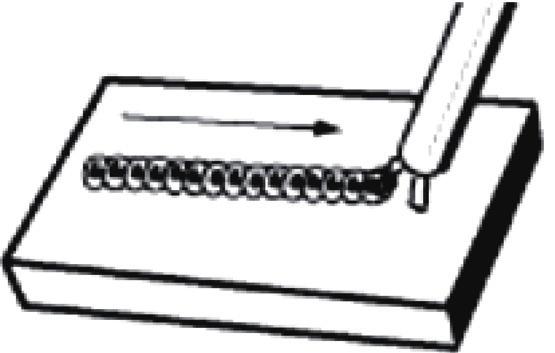
12 5. Operating the welding machine 1) Connect welding machine to power source This welding machine must be grounded while in use to protect the operator from electrical shock. Make sure the power switch is off then connect your welding machine s power cable to a properly grounded 110V-120V or 220V-240 V,50Hz or 60Hz, single phase. 2) Switching on and off a) To start the welding machine, lift the switch on the rear panel to turn on (See Fig 3). The green power indicator light on the front panel is lit and fan begins to spin when the switch is turned on. b) To switch off the welding machine, push the switch down to turn off. 3) Adjusting welding current An appropriate current must be set from 10A to 130A or 160A or 180A or 200A or 250A by turning the welding current selector located on the front panel of the welding machine (See Fig 4). Note: The most difficult aspect of the arc welding process, particularly for beginners, we strongly recommend that you practice on some pieces of scrap metal to get the feel of the operation, before you start on an actual welding job. Generally, the welding current of each electrode is as follow: Size of the welding electrode Thickness of the workpiece Current setting 4) Holding the electrode 1.6 mm 1.6 mm A 2.0 mm 2.0 mm A 2.5 mm 2.5 mm A 3.2 mm 3.2 mm A 4.0 mm mm A 5.0 mm mm A The best way to grip the electrode holder is the way that feels most comfortable to you. Position the electrode to the workpiece when striking the initial arc it may be necessary to hold the electrode perpendicular to the workpiece. Once the arc is started the angle of the electrode in relation to the workpiece should be between 60 0 and 80 0 degrees. This will allow for good penetration, with minimal spatter. 5) Striking the arc Warning: Exposure to a welding arc is extremely harmful to the eyes and skin! Prolonged exposure to the welding arc can cause blindness and burns. Never strike an arc or begin welding until you are adequately protected. Wear flame-proof welding gloves, a heavy long sleeved shirt, trousers without cuffs, high topped shoes, and a welding mask. Scratch the workpiece with the end of electrode to start arc and then raise it quickly about X gap (X=50%-100% diameter of electrode) between the rod and the workpiece (See Fig 5). Note: It is important that the gap be maintained during the welding process and it should be neither too wide or too narrow. If too narrow, the rod will stick to the workpiece. If too wide, the arc will be extinguished. It needs much practice to maintain the gap. The beginners may usually get sticker or arc extinguishing. When the rod is stuck to the workpiece, gently rock it back and forth to make them separate. A good arc is accompanied by a crisp, cracking sound. The sound is similar to that made by eggs frying. To lay a weld bead, only 2 movements are required, downward and in the direction the
13 weld is to be laid (See Fig 6). 6) Types of weld bead The following paragraphs discuss the most commonly used arc welding beads. a) The stringer bead formed by traveling with the electrode in a straight line while keeping the electrode centered over the weld joint (See Fig 7). b) The weave bead used when you want to deposit metal over a wider space than would be possible with a stringer bead. It is made by weaving from side to side while moving with the electrode. It is best to hesitate momentarily at each side before weaving back the other way (See Fig 8). 7) Welding position a) Flat position it is easiest of the welding positions and is most commonly used. It is best if you can weld in the flat position if at all possible as good results are easier to achieve (See Fig 9). b) The horizontal position it is performed very much the same as the flat weld except that the angle is different such that the electrode, and therefore the arc force, is directed more toward the metal above the weld joint. This more direct angle helps prevent the weld puddle from running downward while still allowing slow enough travel speed to achieve good penetration. A good starting point for your electrode angle is about 30 degrees down from being perpendicular to the work piece (See Fig 10). 8) Judge the good weld bead When the trick of establishing and holding an arc has been learned, the next step is learning how to run a good bead. The first attempts in practice will probably fall short of acceptable weld beads. Too long of an arc will be held or the travel speed will vary from slow to fast (See Fig 11). A. Weld speed is too fast. B. Weld speed is too slow. C. Arc is too long. D. Ideal weld. Note: A solid weld bead requires that the electrode be moved slowly and steadily along the weld seam. Warning: Electric shock can kill! To prevent electric shock, do not perform any welding while standing, kneeling, or lying directly on the grounded workpiece. 9) Finish the bead As the coating on the outside of the electrode burns off, it forms an envelope of protective gases around the weld. This prevents air from reaching the molten metal and creating an undesirable chemical reaction. The burning coating, however, forms slag. The slag formation appears as an accumulation of dirty metal scale on the finished weld. Slag should be removed by using a chipping hammer. Warning: Peening the slag from a weld joint causes small chips of metal to fly through the air! Metallic chips flying through the air can cause eye injury or injury to other parts of the head, hands or exposed portions of the body. Wear goggles or safety glasses with side shields and protect the hands and other exposed parts of the body with protective garments, or if possible, work with a shield between the body and the work piece. The intense heat produced at the arc sets up strains in the metal joined by welding. Peening the weld not only removes the scale left behind in the welding but relieves the internal strains developed by the heating and cooling process. 10) Allowed duty cycle Strictly work in conformity with the required duty cycle. If work under over duty cycle, the welding machine may suddenly stop working, and the amber protection indicator light is lit. That's the inner thermal parts work because of over-loading. Under this circumstance, no need to turn off the power
14 switch, leave the fan work to lower the temperature. Generally, it will recover within 4 or 5 minutes at 20 0 C environment temperature. 11) Under Voltage Protection As the grid voltage decreases under 95V or 180V, the welding machine will not work normally, the amber protection indicator light is lit, and the main circuit is cut off. The welding machine may be not switched off, and will restore normal working automatically after the grid restores normal. 12) Over Voltage Protection As the grid voltage exceeds 125V or 260V, the welding machine will not work normally, the amber protection indicator light is lit, and the main circuit is cut off. The welding machine may be not switched off, and will restore normal working automatically after the grid restores normal. MAINTENANCE Warning: Remove the plug from the socket before carrying out any adjustment, servicing or maintenance. 1.Never use water or chemical cleaners to clean your welding machine. Only wipe clean with a dry cloth. 2.Under normal working conditions removing the housing and cleaning your welding machine with dry compressed air at reduced pressure every six months will be quite sufficient. Cleaning at more frequent intervals is advisable if the welding machine is operating in a dusty and dirty environment. 3.Always try to avoid getting particles of metal inside the welding machine since they could cause short circuits. 4. Always store your welding machine in a dry place. 5. Check all cables periodically. They must be in good condition and not cracked. If the cable is damaged, it must be replaced by the manufacturer, its service agent or similarly qualified persons in order to avoid a hazard.
15 TROUBLESHOOTING Problem Possible Cause Solution Unit does not power up Unit is not plugged in Plug in socket Input power circuit breaker not on The main power switch is not working Reset input power circuit breaker Replace main power switch Can not create an arc Workpiece is painted or rusty Remove all paint and rust Protection indicator light is on Electrode holder or ground cable getting hot. Output connections getting hot. Poor welding performance, excessive spatter Electrode sticks Welding bead is too thin Welding bead is too thick Ground clamp is connected where there is paint or rust Ground clamp is not electrically connected to the workpiece Remove all paint and rust so ground clamp is connected to bare metal Make certain the ground clamp is connected to the workpiece Amperage too low for electrode Consult the electrode The internal temperature is too high. The voltage of power supply is lower or higher than required range Weld cable connections loose Weld cable connections have corroded. Damp electrode The electrode is kept in contact with the workpiece for too long while striking an arc The welding travel speed is too fast The welding travel speed is too slow packaging for correct amperage settings. Leave power on and let the fan cool the unit. Output will continue when the unit has cooled. Contact your local power supply enterprise Check to make certain weld cables are tight. Clean weld connections and reinstall. Use fresh and dry electrodes. This will take practice. Keep trying. Reduce the welding travel speed. Maybe incorporate a slight weave over the joint. Increase the welding travel speed. ENVIRONMENT PROTECTION Waste electrical products should not be disposed of with household waste. Please recycle where facilities exist. Check with your Local Authority or retailer for recycling advice.
16 EXPLOSIVE VIEW OF WD U PART LIST OF WD U NO DESCRIPTION Q TY NO DESCRIPTION Q TY
17 EXPLOSIVE VIEW OF WD PART LIST OF WD NO DESCRIPTION Q TY NO DESCRIPTION Q TY
18 EXPLOSIVE VIEW OF WD PART LIST OF WD NO DESCRIPTION Q TY NO DESCRIPTION Q TY 1 Handle 1 17 Fan 1 2 Housing 1 18 Output inductance 1 3 Current-carrying plate 1 19 Transformer 1 4 Current selector knob 1 20 Bridge rectifiers 1 5 Shade of LED 2 21 Radiator 1 6 Digital display instrument 1 22 IGBT single tube 4 7 Front cover 1 23 Radiator 2 8 Base plate 1 24 Support bar of IGBT radiator 1 9 Quick connector 2 25 Rear cover 1 10 Radiator 1 26 Fan 1 11 Insulation paper plate 1 27 Cable and plug 1 12 Current-carrying plate 1 28 Cable gland 1 13 Support bar of rectifier radiator 1 29 Power switch 1 14 Main PCB 1 30 Belt 1 15 Control PCB 1 31 Ground clamp with cable 1 16 Fast recovery diode 4 32 Electrode holder with cable 1
19 9 EXPLOSIVE VIEW OF WD PART LIST OF WD NO DESCRIPTION Q TY NO DESCRIPTION Q TY 1 Base plate 1 19 Output inductance 1 2 Support bar 1 20 Front cover 1 3 Insulation paper plate 1 21 Washer 3 4 Support bar of IGBT radiator 1 22 Nut 1 5 Radiator 2 23 Shade of LED 2 6 Power switch 1 24 Current selector knob 1 7 IGBT single tube 4 25 Current-carrying plate 1 8 Cable gland 1 26 Current-carrying plate 1 9 Cable and plug 1 27 Quick connector 2 10 Rear cover 1 28 Digital display instrument 1 11 Fan 1 29 Electrode holder with cable 1 12 Electrolytic capacitor 4 30 Ground clamp with cable 1 13 Main PCB 1 31 Thermal protector 1 14 Housing 1 32 Transformer 1 15 Handle 1 33 Fan 1 16 Belt 1 34 Fast recovery diode 4 17 Bridge rectifiers 2 35 Radiator 1 18 Control PCB 1 36 Radiator 1
20 EXPLOSIVE VIEW OF WD PART LIST OF WD NO DESCRIPTION Q TY NO DESCRIPTION Q TY
21 WD U/WD /WD /WD /WD
22 WD U/WD /WD /WD /WD
23 WD U/WD /WD /WD /WD
24 MADE IN CHINA WIDO Machinery Co., Ltd. All rights reserved.