Phase Transformation in Materials
|
|
|
- Damon Ward
- 5 years ago
- Views:
Transcription
1 2016 Fall Phase Transformation in Materials Eun Soo Park Office: Telephone: Office hours: by an appointment 1
2 Equilibrium in Heterogeneous Systems In X 0, G β 0 > G α 0 > G 1 α + β separation unified chemical potential μ A = μ a Aα =a A β G A G a α =a β -RT lna A α -RT lna A β μ A G e -RT lna α -RT lna β μ α 4 α 1 β 1 β 4 2
 oth are ideal soln.")
3 - inary phase diagrams 1) Simple Phase Diagrams H = 0 H = 0 Assume: (1) completely miscible in solid and liquid. (2) oth are ideal soln. L mix S mix 2) Variant of the simple phase diagram l H α l > > 0 mix < H mix < 0 mix H mix H α miscibility gab Ordered phase 3
4 H < > 0 : Solid solution solid state H >> < 0 S mix phase separation (two solid solutions) S mix : liquid state phase separation (up to two liquid solutions) stable miscibility gap metastable miscibility gap H H << 0 S mix < 0: Solid solution ordered phase : Compound : A, A 2 S mix 4
5 Summary I : inary phase diagrams 1) Simple Phase Diagrams oth are ideal soln. 1) Variation of temp.: G L > G s 2) Decrease of curvature of G curve 2) Systems with miscibility gap 4) Simple Eutectic Systems 3) Ordered Alloys H = 0 H > 0 5) Phase diagrams containing intermediate phases L mix ( decrease of -TΔS mix effect) S mix 1)Variation of temp.: G L > G s 2)Decrease of curvature of G curve + Shape change of G curve by H H = 0 H >> 0 miscibility gap extends to the melting temperature. L mix S mix H = 0 H < 0 ΔH mix < 0 A atoms and atoms like each other. Ordered alloy at low T ΔH mix << 0 The ordered state can extend to the melting temperature. Stable composition = Minimum G with stoichiometric composition L mix S mix 5
6 The Gibbs Phase Rule For Constant Pressure, P + F = C single phase F = C - P + 1 = = 2 can vary T and composition independently two phase F = C - P + 1 = = 1 can vary T or composition 3 eutectic point F = C - P + 1 = = 0 can t vary T or composition 6
7 1.5.7 Effect of T on solid solubility T e X A is virtually insoluble in Unstable α form Stable β form A is virtually insoluble in. µ o α G G = β α α G RT o G α = µ ln α β α + Ω(1 0 ( here, X G X e X e RT >> X β α ln G α o G X β = Ω(1 = G << 1) X X = = Ω(1 X e e e = H S = exp( R ) o X β α = G 2 G ) + RT ln α ) 2 2 µ G = exp( β α β α Q = Aexp RT β = X o RT ln RT ln Ω(1 X β α T S Ω β β α H )exp( G X ) α X 2 α + Ω ) RT 이므로 µ α + Ω ) RT Q : heat absorbed (enthalpy) when 1 mole of β dissolves in A rich α as a dilute solution. β T β β µ ~ G = _ α e X 7
8 * Limiting forms of eutectic phase diagram The solubility of one metal in another may be so low. X e Q = Aexp RT a) T e X b) It is interesting to note that, except at absolute zero, X e can never be equal to zero, that is, no two compo -nents are ever completely insoluble in each other. 8
9 a) 평형에미치는공공의영향 Equilibrium concentration at equilibrium will be that which gives the minimum free energy. dg dx e V X = X V V = 0 e H T S + RTln X = 0 V V V A constant ~3, independent of T e SV HV XV = exp exp R RT putting G = H T S e G XV = exp RT V V V V Rapidly increases with increasing T In practice, H V is of the order of 1 ev per atom and X V e reaches a value of about 10-4 ~10-3 at the melting point of the solid Fig Equilibrium vacancy concentration. : adjust so as to reduce G to a minimum 9
10 The G curves so far have been based on the molar Gs of infinitely large amounts of material of a perfect single crystal. Surfaces, Gs and interphase interfaces have been ignored. 1.6 Influence of Interfaces on Equilibrium ΔG = ΔP V Extra pressure ΔP due to curvature of the α/β P = 2γ r G = 2γV r m The concept of a pressure difference is very useful for spherical liquid particles, but it is less convenient in solids (often nonspherical shape). dg = ΔG γ dn = γda Since n=4πr 3 /3V m and A = 4πr 2 Early stage of phase transformation Interface (α/β)=γ - b) 평형에미치는계면의영향 ΔG γ = γda/dn 2γVm G = r Spherical interface Planar interface Fig The effect of interfacial E on the solubility of small particle Fig Transfer of dn mol of β from large to a small particle. 10
11 Gibbs-Thomson effect (capillarity effect): Free energy increase due to interfacial energy Quite large solubility differences can arise for particles in the range r=1-100 nm. However, for particles visible in the light microscope (r>1um) capillarity effects are very small. X e X X X e r= r= Q = Aexp RT G + Ω = exp( ) RT G + Ω = exp( ) RT r G + Ω 2γV = exp( RT r= 2γVm = X exp( ) RTr m / r ) For small values of the exponent, X X r= r r= 2γVm 2γV = exp( ) 1+ RTr RTr m Fig The effect of interfacial energy on the solubility of small particles. Ex) γ=200mj/m 2, V m =10-5 m 3,T=500K X r = 1 + X 1 r( nm) 11 For r=10 nm, solubility~10% increase
12 1.8 Additional Thermodynamic Relationships for inary Solutions Gibbs-Duhem equation: Calculate the change in (dμ) that results from a change in (dx) X dµ + X dµ = A A 0 Comparing two similar triangles, dµ dµ d( µ = = X X 1 A µ A A ) dg µ µ A = dx 1, d 2 G/dX 2 d 2 G/dX 2 =d 2 G/dX A 2 Substituting right side Eq. & Multiply X A X 2 dg A µ A µ A 2 X d = X d = X X dx dx Eq
13 Additional Thermodynamic Relationships for inary Solutions The Gibbs-Duhem Equation 합금조성의미소변화 (dx) 로인한화학퍼텐셜의미소변화 (dμ) 를계산 be able to calculate the change in chemical potential (dμ) that result from a change in alloy composition (dx). 1 For a regular solution, G = XAGA + XG +Ω XAX + RT(XAln XA + Xln X ) 2 d G RT 2 2 dx X AX = Ω For a ideal solution, Ω = 0, 2 d G dx 2 = RT X X A 2 Different form Eq Differentiating With respect to X, µ = G + RT lna = G + RT ln γ X γ = a /X dµ RT X dγ RT d ln γ = 1+ = 1+ dx X γ dx X d ln X 13
14 dµ RT X dγ RT d ln γ = 1+ = 1+ dx X γ dx X d ln X Eq a similar relationship can be derived for dμ A /dx dln γ A dln γ X dµ = X dµ = RT 1+ dx = RT 1+ dx dln X A dln X A A 2 dg A µ A µ A 2 X d = X d = X X dx dx Eq Eq The Gibbs-Duhem Equation 2 dg dln γ A dln γ X AX = RT 1 RT = + dx dln X A dln X be able to calculate the change in chemical potential (dμ) that result from a change in alloy composition (dx). 14
15 Total Free Energy Decrease per Mole of Nuclei G 0 : 변태를위한전체구동력 / 핵생성을위한구동력은아님 Driving Force for Precipitate Nucleation G V 1 α β α β µ A X A µ X G = + : Decrease of total free E of system by removing a small amount of material with the nucleus composition (X β ) (P point) β β β β G 2 = µ A X A + µ X : Increase of total free E of system by forming β phase with composition X β (Q point) G n = G 2 G 1 (length PQ) G = V V G V m For dilute solutions, n per unit volume of β G X where X = X X G V : driving force for β precipitation X T 0 e 15 undercooling below T e

16 Summary II: inary phase diagrams - Gibbs Phase Rule F = C P + 1 (constant pressure) Gibbs' Phase Rule allows us to construct phase diagram to represent and interpret phase equilibria in heterogeneous geologic systems. Effect of Temperature on Solid Solubility Equilibrium Vacancy Concentration Influence of Interfaces on Equilibrium G = 2γV r m Gibbs-Thomson effect Gibbs-Duhem Equation: e able to calculate the change in chemical potential that result from a change in alloy composition. 2 dg dln γ A dln γ X AX = RT 1 RT = + dx dln X A dln X 합금조성의미소변화 (dx) 로인한화학퍼텐셜의미소변화 (dμ) 를계산 16
17 What are ternary phase diagram? Diagrams that represent the equilibrium between the various phases that are formed between three components, as a function of temperature. Normally, pressure is not a viable variable in ternary phase diagram construction, and is therefore held constant at 1 atm. 17
18 Gibbs Phase Rule for 3-component Systems 18

19 Gibbs Triangle An Equilateral triangle on which the pure components are represented by each corner. Concentration can be expressed as either wt. % or at.% = molar %. X A +X +X C = 1 Used to determine the overall composition 19
20 Overall Composition 20
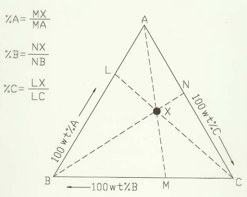
21 Overall Composition 21
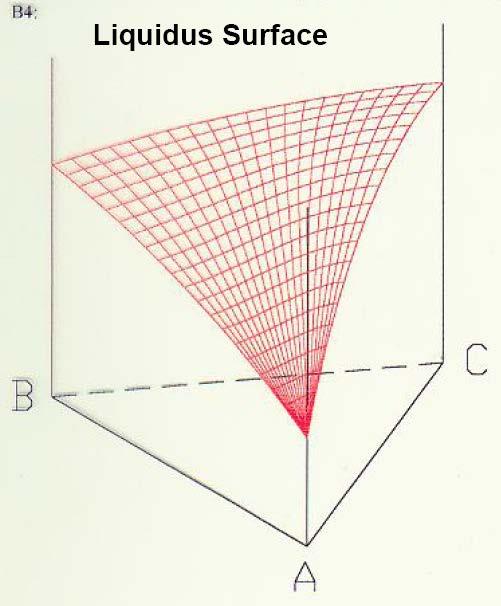
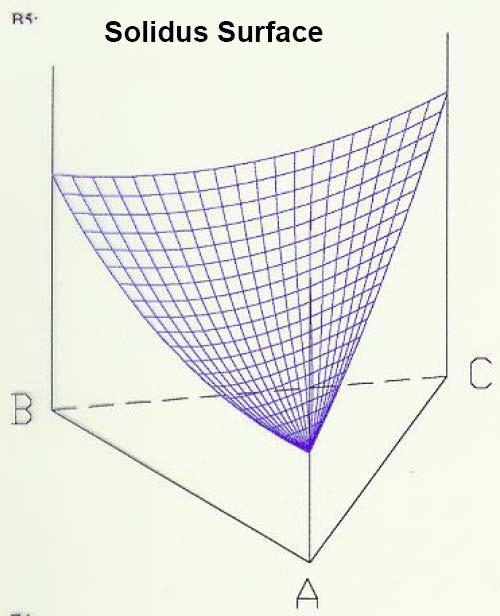
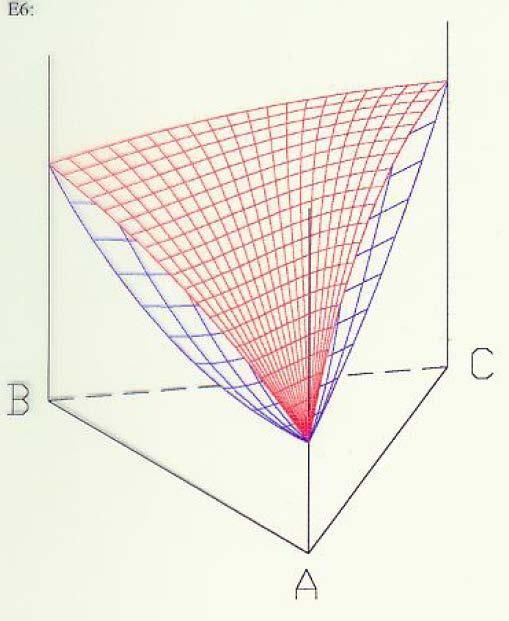
22 Ternary Isomorphous System Isomorphous System: A system (ternary in this case) that has only one solid phase. All components are totally soluble in the other components. The ternary system is therefore made up of three binaries that exhibit total solid solubility. The Liquidus surface: A plot of the temperatures above which a homogeneous liquid forms for any given overall composition. The Solidus Surface: A plot of the temperatures below which a (homogeneous) solid phase forms for any given overall composition. 22


23 Ternary Isomorphous System T T C T T C T T C 23

24 Ternary Isomorphous System T C T 24
25 Ternary Isomorphous System T C T C T T 25

26 Ternary Isomorphous System T C T T T C 26

27 Ternary Isomorphous System Isothermal section F = C - P T C T 27


28 Ternary Isomorphous System Isothermal section T C T 28
29 Ternary Isomorphous System Isothermal section F = C - P Fig (a) Free energy surface of a liquid and three solid phases of a ternary system. (b) A tangential plane construction to the free energy surfaces defined equilibrium between s and l in the ternary system (c) Isothermal section through a ternary phase diagram 29

30 Ternary Isomorphous System Locate overall composition using Gibbs triangle 30
31 31


32 Ternary Eutectic System (No Solid Solubility) T C T T T T C T C 32


33 Ternary Eutectic System (No Solid Solubility) Liquidus projection T C T 33
 T C")
34 Ternary Eutectic System (No Solid Solubility) T C T 34
 T C")
35 Ternary Eutectic System (No Solid Solubility) T C T 35
 T C")
36 Ternary Eutectic System (No Solid Solubility) T C T 36
 T C")
37 Ternary Eutectic System (No Solid Solubility) T C T 37
 T C")
38 Ternary Eutectic System (No Solid Solubility) T C T 38
 T C")
39 Ternary Eutectic System (No Solid Solubility) T C T 39
40 Ternary Eutectic System (No Solid Solubility) T= ternary eutectic temp. A C L+A+C L+A+ L++C 40
")
41 Ternary Eutectic System (with Solid Solubility) 41
 T C T C T T")
42 Ternary Eutectic System (with Solid Solubility) T C T C T T 42


43 Ternary Eutectic System (with Solid Solubility) T T C 43


44 Ternary Eutectic System (with Solid Solubility) T TC 44


45 Ternary Eutectic System (with Solid Solubility) T T C 45


46 Ternary Eutectic System (with Solid Solubility) T T C 46


47 Ternary Eutectic System (with Solid Solubility) T T C 47


48 Ternary Eutectic System (with Solid Solubility) T TC 48

49 Ternary Eutectic System (with Solid Solubility) T= ternary eutectic temp. C L+β+γ L+α+β L+α+γ 49
 T T C 정해솔학생제공자료참조 : 실제")

50 Ternary Eutectic System (with Solid Solubility) T T C 정해솔학생제공자료참조 : 실제 isothermal section 의온도에따른변화 50
")

51 Ternary Eutectic System 3) Solidification Sequence: liquidus surface 51
52 * Vertical section Ternary Eutectic System * The horizontal lines are not tie lines. (no compositional information) * Information for equilibrium phases at different tempeatures 52
53 < Quaternary phase Diagrams > Four components: A,, C, D Assuming isobaric conditions, Four variables: X A, X, X C and T A difficulty of four-dimensional geometry further restriction on the system Most common figure: equilateral tetrahedron 4 pure components 6 binary systems 4 ternary systems A quarternary system 53
54 * Draw four small equilateral tetrahedron formed with edge lengths of a, b, c, d a+b+c+d=100 %A=Pt=c, %=Pr=a, %C=Pu=d, %D=Ps=b 54
55 Topic proposal for materials design Please submit 3 materials that you want to explore for materials design and do final presentations on in this semester. Please make sure to thoroughly discuss why you chose those materials (up to 1 page on each topic). The proposal is due by September 28 th on etl. Ex) stainless steel/ graphene/ OLED/ io-material/ Shape memory alloy ulk metallic glass, etc. 55
56 * Incentive Homework 1 Please submit ternary phase diagram model which can clearly express 3D structure of ternary system by October 17 in ldg You can submit the model individually or with a small group under 3 persons. * Homework 1 : Exercises 1 (pages 61-63) Good Luck!! 56

57 57