Computational Weld Mechanic Simulations
|
|
|
- Ami Haynes
- 5 years ago
- Views:
Transcription
1 Selection of Validation Parameters Suitable for Computational Weld Mechanic Simulations Christopher Bayley DRDC Atlantic / DLP Victoria, BC John Goldak Goldak Technology Inc. Ottawa, ON May 2012
2 Overview Motivation Computational Weld Mechanics Overview of the Weld Overlay Program Defining What is Good Enough Examples of Validation Parameter Data Discussion 1
3 Project Motivation 1. Develop an understanding of whether past weld repairs have influenced structural performance. 2. Development of future weld build-up standards. 2
 Coupled")


 Involves")


4 Computational Welding Mechanics (Un) Coupled multi-physics simulations: Involves temperature dependent material properties Mechanical (Flow stress, Elastic Modulus, ) Thermal (Conductivity, thermal expansion, ) Morphology (Phase changes, ) Involves Heat generation Are time and path dependent due to the deposition of weld metal Have additional thermal boundary conditions Convection and conduction must be considered. 3
5 Weld Modelling Features Goldak Technology Incorporated VrWeld ( Involves separate thermal, microstructural and structural simulations. Pass-by-pass fill sequence used to capture non-symmetrical deformation. Material property selection tied to chemical composition. Thermally dependent material properties Microstructural predictions 4
6 Verification and Validation Verification Ensuring mathematical representation of the physical phenomena is correctly implemented Responsibility of the Code Developer Validation Requires an estimate of the difference between experimentally measured parameters and a computational model. Requires the selection of physically relevant criteria 5
7 Defining what is Good Enough Dependent on the modelling objectives: Absolute predictions (i.e. Prediction of critical weld distortion) requires greater accuracy Relative Predictions (i.e. Minimization studies associated with procedure variations) requires greater precision i Is a transient validation required if all that is of interest is the final equilibrated state? 6
8 Overview of Weld Build-Up Program Outcome How Weld procedure Understanding how CWM and Experimental optimization welding influences distortion and residual stresses Serve as basis for verification and validation Weld procedure qualification DefStan Parts A&B Experimental Weld overlay standard development Weld area size limitations Area location limitations CWM 7
9 Types Validation Parameters Transient Iso-Static Single Point Measurements Multiple Point Measurements Temperature Thermocouple - Displacement LVDT Digital Image Correlation Strain Strain Gauge Digital Image Correlation Residual Stress - Diffraction (Neutron/X-ray) Microstructure - Micro Hardness 8


10 Examples of Validation Samples Picture Frame # Samples Temper Bead Study Transient Distortion Transient Strain Bead On Plate Transient Temp. Iso Static Residual Stress Cylinders Picture 2 No Yes Yes Yes No Frame Bead on 4 Yes Yes Yes No No Plate Cylinders 8 No Yes Yes No No Temper Bead 3 No No Yes No Yes Study Iso Static Micro Structure 9


11 10 Transient Instrumentation - Temperature


12 Transient Instrumentation - Temperature 11 Peak temperature is highly dependent on relative location to heat sources Correctly capturing measurement location as important as the data itself


13 Transient Instrumentation - Displacement Increase Power 12


14 Transient Instrumentation - Strain EMF associated with welding arc marks the welding start and stop Convenient to mark the incremental change in strains associated with each pass 13


15 Transient Instrumentation - Strain Orientation T L Strain sensitive i to relative distance between sensor and heat source Monitoring strain more sensitive than displacement 14


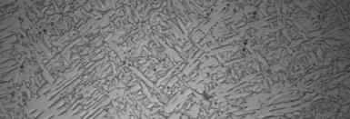
16 Iso-Static - Microstructural Predictions 15 Temper Bead Study 0.8 kj/mm, AWS 9016 Consumable


17 Relevance of Microstructural Predictions EB Specimen slow-1 (HI~1.3 kj/mm) 16


18 Iso Static - Residual Stress Predictions Longitudinal Stress Component Along Weld Measured Neutron Diffraction Predicted Difference 17


19 18 Iso-Static Out of Circularity
20 Comparison of Validation Parameters Transient Thermal Data Ensures that the thermal boundary conditions, weld start & stop, interpass time, heat input are satisfactorily captured Located within steep gradient Transient Strain Gauge Data Sensitive to transient variations in local strain and thermal expansion and contraction associated with each welding pass. Robust method for marking the weld start and stop Located within steep strain gradient, Errors compound over measurement timespan Difficult to infer global behaviour for localized measurement 19
21 Comparison of Validation Parameters Transient Displacement Data Single point data provides global response due to localized effects Multi-point data from Digital Image Correlation superior Applicable to structural performance Iso-Static Residual Stresses Provides an absolute stress measurement not relative difference due to welding Experimental challenges (sampling volume, sample preparation) Time, availability and cost 20
22 Comparison of Validation Parameters Iso Static Microstructural Hardness Required input for process optimization Validation for weld process parameters (Heat Input) Iso Static - Net Shape Path independent Applicable to structural performance No knowledge of when/why/where problems arose 21
23 Summary Validation Requires an estimate of the difference between experimentally measured parameters and a computational model. Sl Selection of parameters is application dependent, d tbt but should include as many outputs as possible Transient validations help confirm that solutions not fortuitous. Determination of Good Enough dependent on application. 22
24 Summary Weld Overlay Distortion Not Intuitive Welding induced strain and displacement not intuitively related. Comparison between different configurations, weld areas, and boundary conditions not intuitive iti Compounds difficulty in class wide area/location limitations as local boundary conditions influence distortion. Cylinder Collapse Simulations Not adversely affected by Weld Overlay Girth welds have a significant influence Minor influence of weld metal composition 23


25 0 Thank You